JWM Posted February 23, 2019 Author Share Posted February 23, 2019 Hi, Many thanks for support! I strted to work on surfaces. I bought the an special tool - the rivet maker from Trumpeter. I begun with fuselage side floats: from bottom: And tailplane This Trumpeter tool is that on above with circle end. The second tool used for making surface is a home made "hook" used for cutting (tracing) pannel lines. Third one is scaler, used together with this "hook". First I am drawing lines using permament maker to guide hand with rivet maker, After rolling I am washing surface with ethanol. I really like the result: And current shape of whole fuselage. Please note drilled opening for stro dome To be continued Regards J-W 7 Link to comment Share on other sites More sharing options...
TallBlondJohn Posted February 23, 2019 Share Posted February 23, 2019 (edited) Glad you haven't fallen into the trap of scribing panel lines - Clippers didnt have any! Flying boats and panel gaps don't mix. For the record the joins were all closely riveted or welded, leaving a slightly raised line. Looks like the tool is working nicely. Edited February 23, 2019 by TallBlondJohn 1 Link to comment Share on other sites More sharing options...
JWM Posted February 23, 2019 Author Share Posted February 23, 2019 (edited) Thank you, @TallBlondJohn. I have question. A rare photo right from a belly of one wartime Clipper Besides US flags on fuselage floats (visible on other photos too, but here interesting is orientation - not sure where it is on which crorner the stars are on left float? Is is orieted the same way like on the right one?) interesting is also a dark spot on right win? Is it another US flag? Look for like it... Moreover - the shots from top are even more rare (for wartime colour machines, not the silver ones). Here is take of Yankee Clipper after crash in Lisbon. The astro dome is seen on left so right from it this is left wing top. I see there another US flag - or something recalling white and red strips of flag. and the stars on deep blue are close to leading edge toward engine. This flag is just outside outer engine. .. So on bottom should be in symmetric position. This was not shown on any colour profile I/ve seen so far Cheers J-W Added after about hour: Indeed there was flag on top of wing: Cheers J-W Edited February 23, 2019 by JWM added PS Link to comment Share on other sites More sharing options...
TallBlondJohn Posted February 23, 2019 Share Posted February 23, 2019 (edited) For general information of future readers - In some photos I've seen, there is a US flag on the top port wing, never on the starboard (that's got the registration of course). The reg is repeated on the port wing underside. The top flag is usually the width of the International Orange visibility stripe and can be 'rigid or 'wavy'. (The tricky thing with Clippers is the great variation of simple elements - wing boots for instance as they got introduced across the fleet, and markings changing in service.) The Lisbon crash (what a sad sight) seems to have a much larger flag, I guess for wartime wear (as you say there aren't many wartime pics). I've never seen a flag on the bottom of the starboard wing, but then again I've never seen the bottom of an obviously wartime Clipper! In the photo above I'm sure both flags are the same orientation, with the stars starboard front (if you rotate the photo you can see the quarters line up). The wing-thing has a darker corner in the same place so yes I think its another flag. And I have a theory about this flag. This clipper may have had peacetime wing flags (they weren't on the earlier planes as built, they appeared later and Capetown was a later B314A). Then the big wartime flags have been added to the floats, with the underwing flag left in the right place but now looking rather lost. Meanwhile the upper surface flag has been repainted in the larger wartime size, and moved inboard at the same time to match the stripe width (there may be a war on, but one has to have standards). Of course its possible the smaller top wing flag was simply left in place as well, in which case it must have looked rather pathetic next to its bigger brother. JW, I'm assuming your internet searches are finding the same pics I did, but I did get some photos off the Foynes Museum site before they put them behind a pay wall. If there's anything you want me to check just ask, or maybe I could bundle up what I have and send the lot? Edited February 23, 2019 by TallBlondJohn 1 Link to comment Share on other sites More sharing options...
JWM Posted February 23, 2019 Author Share Posted February 23, 2019 16 minutes ago, TallBlondJohn said: JW, I'm assuming your internet searches are finding the same pics I did, but I did get some photos off the Foynes Museum site before they put them behind a pay wall. If there's anything you want me to check just ask, or maybe I could bundle up what I have and send the lot? Edited 9 minutes ago by TallBlondJohn Many thanks John. Surely when a new question will arrise, I will send it directly to you. Currently I am gathering photos of beech buggy (or rathem the land-platform). I glued two small magnets inside fuselage to make platform removable, but attached! Regards J-W Link to comment Share on other sites More sharing options...
TallBlondJohn Posted February 23, 2019 Share Posted February 23, 2019 Here are all the photos I have with a half-decent view of the trolley: I'm sure I've seen a resin kit that included a trolley, and Shapeways have a trolley as part of their 1/1250 model, worth a look? 1 Link to comment Share on other sites More sharing options...
JWM Posted February 23, 2019 Author Share Posted February 23, 2019 11 minutes ago, TallBlondJohn said: I'm sure I've seen a resin kit that included a trolley, and Shapeways have a trolley as part of their 1/1250 model, worth a look? Many thanks!!! I've found some photos but of such quality. Indeed the Anigrand Clipper in 1/72 has this trolley However I do not see wheels of trolley here. But the side fins are missing on this photo as well... Best regards J-W Link to comment Share on other sites More sharing options...
TallBlondJohn Posted February 23, 2019 Share Posted February 23, 2019 The wheels are moulded as part of the trolley. Pity we cant see more detail. Just found this build thread, very interesting but in French: http://fighters.forumactif.com/t68738-boeing-314-honolulu-clipper Sacre bleu, he's put the bulb aerial on the centreline - wrong! Oh well... 1 Link to comment Share on other sites More sharing options...
JWM Posted February 23, 2019 Author Share Posted February 23, 2019 Many thnks! BTW - searching for different photos of Clipper I ahve found Winston Churchill in cockpit of Boeing 314! https://twitter.com/WWIIpix/status/1060220275361484800 Regards J-W Link to comment Share on other sites More sharing options...
TallBlondJohn Posted February 23, 2019 Share Posted February 23, 2019 1 minute ago, JWM said: Many thnks! BTW - searching for different photos of Clipper I ahve found Winston Churchill in cockpit of Boeing 314! https://twitter.com/WWIIpix/status/1060220275361484800 Regards J-W Yes he loved having a go at driving, but the passengers dreaded it. Apparently he was a rubbish pilot, the plane crabbed all over the place and made everybody ill. 2 Link to comment Share on other sites More sharing options...
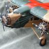
JWM Posted February 24, 2019 Author Share Posted February 24, 2019 (edited) I started to prepare trolley Engines: cowlings are from Combat models, props are Lancaster Revell, engines are resin copies of MPM/SH Boston, I cut out ailerons - I think that separate will look better Edited February 24, 2019 by JWM 3 Link to comment Share on other sites More sharing options...
JWM Posted February 24, 2019 Author Share Posted February 24, 2019 Interestig are differecnies in exhaust pipe position and in inlets to engines betweem left and roght sides: Cheers J-W 3 Link to comment Share on other sites More sharing options...
JWM Posted February 27, 2019 Author Share Posted February 27, 2019 Hi, Next putting/sanding of fuselage. The hull seems to look OK now I started to construct canopy (again Mozart kugels box) However the main problem is with engine nacelles. First I have to gave them regular shapes (you may compare to initial photos) I was thinking how construct the engines. I decided to add a circle glued from back to engine I glued this circles to resin engines (how strong it will be?) and I will glue this way engines inside cowlings To be cont. REgards J-W 5 Link to comment Share on other sites More sharing options...
JWM Posted March 2, 2019 Author Share Posted March 2, 2019 Hi I worked on props and engines. I used 2 mm diameter brass tube as prop axes. Glued inside (a bit reduced diameter short rod at prop back) using CA glue. The props were painted from Tamiya rattle can with silver. The resin engines I drilled out using 2 mm drill and then increase a bit diameter using another tool: Frem back I secured props to be ratable I was continuing work on wings (surface and nacelles) To be cont. Regards J-W 4 Link to comment Share on other sites More sharing options...
JWM Posted March 3, 2019 Author Share Posted March 3, 2019 On many photos one can notice an asymmetry in inlets and exhaust pipes which I mentioned in post# 37 above. It is for example for NC18603 and NC18607, so likely for Dixi Clipper which has registration between them (NC18605) it exists also. This is related to shifting back exhaust pipes on left wing. Were they a part of heating system for passanger deck? Another technical question - I do not see outlets from oild coolers, which inlets are on leading edge, two each side of each engine. ON B17 they were on top of wing. Here nothing like it exists... On photo above aomething is visible, what looks like additional cooler under the external left engin but it is something between the engines, what only looks like attached to external engine? Is it another element of this what happen with inlets and exhaust pipes? It could be nice to understand why there were those assymetries? Meanwhile I did a kind of ledder on left front of nose: I did some work on trolley: I am affraid that It is perhaps not a very acurate model of trolley, but I think it contains general ideas which I could observe on photos.... To be cont. Regards J-W Regards J-W 3 Link to comment Share on other sites More sharing options...
TallBlondJohn Posted March 4, 2019 Share Posted March 4, 2019 Vaguely related - the BBC have done an article on the importance of Fiji in the development of GPS for air travel. Good read, but bear with me... http://www.bbc.com/travel/story/20190303-how-fiji-changed-the-way-we-travel The navigator's desk halfway down is from a Clipper. Most 30s airliners had slightly less room! I have no idea about oil cooler outlets - could the hot air have been retained for heating? 3 Link to comment Share on other sites More sharing options...
JWM Posted March 4, 2019 Author Share Posted March 4, 2019 Thank you John. The inside of cockpit is more like on a cruiser (ship) not the airplane, so spacy! Andthe plug - at cable of lamp! cheers J-W Link to comment Share on other sites More sharing options...
TallBlondJohn Posted March 4, 2019 Share Posted March 4, 2019 On 3/3/2019 at 9:49 PM, JWM said: I do not see outlets from oild coolers, which inlets are on leading edge, two each side of each engine. Hi JWM, I've checked my photos and I can only see one intake per engine, always just outboard. Just in case this wasnt a typo 🙂 1 Link to comment Share on other sites More sharing options...
TallBlondJohn Posted March 4, 2019 Share Posted March 4, 2019 4 minutes ago, JWM said: Thank you John. The inside of cockpit is more like on a cruiser (ship) not the airplane, so spacy! Andthe plug - at cable of lamp! cheers J-W Also note gun for use on any members of the working class who get within a hundred yards. (And flares.) 😉 2 Link to comment Share on other sites More sharing options...
JWM Posted March 4, 2019 Author Share Posted March 4, 2019 3 minutes ago, TallBlondJohn said: Hi JWM, I've checked my photos and I can only see one intake per engine, always just outboard. Just in case this wasnt a typo 🙂 I was suggested by below photo, that there are two oil coolers on both sides, the inside is not well visible, but there is something! Cheers J-W 1 Link to comment Share on other sites More sharing options...
KRK4m Posted March 4, 2019 Share Posted March 4, 2019 On 3/3/2019 at 10:49 PM, JWM said: On photo above aomething is visible, what looks like additional cooler under the external left engin but it is something between the engines, what only looks like attached to external engine? Is it another element of this what happen with inlets and exhaust pipes? It could be nice to understand why there were those assymetries? Exactly this inlet is located midway between the two portside engines - look at the frontal view of BOAC Clipper you have inserted earlier. Cheers Michael 1 Link to comment Share on other sites More sharing options...
JWM Posted March 4, 2019 Author Share Posted March 4, 2019 This inlet on the lower part of wing is visible on above photo. But the oil coolers are in the leading edge. But this wider take o fthe same photo is not showing them on side toward fuselage on the outer engines: 1 Link to comment Share on other sites More sharing options...
TallBlondJohn Posted March 4, 2019 Share Posted March 4, 2019 (edited) The weird white lines are the curves of the open nacelle access doors. I think that makes it look something inboard of the port inner, but its not visible on any British Clippers. Maybe Roosevelt's had a modification, but I doubt it. What the BOAC clippers did have is some sort of probably brass cap, which is usually not visible in Pan Am clippers, probably painted black. Of course the position varies! The small inlet further back between the engines is on all Clippers, but only ever the port wing. Clearly the two wings had different plumbing. Edited March 4, 2019 by TallBlondJohn 3 Link to comment Share on other sites More sharing options...
JWM Posted March 4, 2019 Author Share Posted March 4, 2019 Thank you Mike and John! Photos from now - I've just glued together fuselage with wings! Just to show size - with Curtiss Segull, which I am doing now also: Cheers J-W 6 Link to comment Share on other sites More sharing options...
72modeler Posted March 5, 2019 Share Posted March 5, 2019 In looking at photos of the Clippers, it appears to me that the oil cooler intakes are located just outboard of each engine just under the centerline of the wing leading edge. I think the oil cooler outlets might be the square ports that are located on the outboard side of each engine nacelle on the wing upper surface, just forward of the wing walkway stripes. I have attached a photo that I think shows the oil cooler outlets. See what you think. Mike https://www.flyingboatmuseum.com/boeing-314-clipper-flying-boat/ 1 Link to comment Share on other sites More sharing options...

Recommended Posts
Create an account or sign in to comment
You need to be a member in order to leave a comment
Create an account
Sign up for a new account in our community. It's easy!
Register a new accountSign in
Already have an account? Sign in here.
Sign In Now