Mancunian airman Posted November 9, 2018 Share Posted November 9, 2018 In a bid to reduce my Flickr numbers, I shall just post the box cover and front sheet that gives codes and paint color call outs plus the sprues in the bag . . . As I get into the build I will show the appropriate page as necessary This comes as a separate entity as you have a choice of building a canvas covered rear body or an open tilt body . . . As with the 1/72nd -- 1/76th issue with compatibility with aircraft, I am considering using this 1/35th scale alongside a 1/32nde aircraft . . . . Ian 7 Link to comment Share on other sites More sharing options...
Corsairfoxfouruncle Posted November 9, 2018 Share Posted November 9, 2018 Shame Flickr is doing this. Looking forward to seeing this though. 👍 Link to comment Share on other sites More sharing options...
Mancunian airman Posted November 12, 2018 Author Share Posted November 12, 2018 I have received the Panzer Art resin wheels so should be on this within a few days . . . . Link to comment Share on other sites More sharing options...
Yetifan Posted November 12, 2018 Share Posted November 12, 2018 Saw loads of IBG at IPMS and they really look great, will follow with interest 🙂 Link to comment Share on other sites More sharing options...
Mancunian airman Posted November 12, 2018 Author Share Posted November 12, 2018 Made a start but not yet following the instructions. A few things that I spotted straight away needed attention I thought . . . . The wheel arches for the front wheels are relatively thin but I have thinned them down a little more . . . . The kit is molded with utter great hinges over the windscreens so they had to go . . . . The plastic is really soft so I took a chance and cut out the drivers door . . . . I have got to admit that these IBG kits are new to me so I will be going steady and dry fitting and check stuff as I discover how things go together. There has been mention of the instructions being 'dark' ; I dont think they are that bad. The instructions dont give any colour indications to parts, ie the engine, but I do know that the basic vehicle frame and camouflage colours are not an issue as I will be using info that I have for the smaller scale I build. More to come . . . . Ian 5 Link to comment Share on other sites More sharing options...
Bullbasket Posted November 13, 2018 Share Posted November 13, 2018 I've got the very same kit, so I will be picking your brains/build for any problems. John. 1 Link to comment Share on other sites More sharing options...
AntPhillips Posted November 13, 2018 Share Posted November 13, 2018 I've got this one on my future wanted list, I'll be following with interest 1 Link to comment Share on other sites More sharing options...
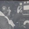
Mancunian airman Posted November 14, 2018 Author Share Posted November 14, 2018 (edited) Sub assemblies There has been previous reviews stating that this kit offers poor location adhesive points and when building the engine this is the case. 3 items are located on the engine cylinder block purely against slight curvatures which you really have to look at . . . dont do what I did and place part B59 in the curve without realising that in needs to be place at the front end of the block so that the fan belt will come into contact with it :-(. If there had been a location pin of sorts this probably wouldn't have happened. Cutting some of the parts off the sprue was difficult in some cases due to the thickness of the injection right up to the piece so after a few nipper cuts, I used a small scalpel blade directly up to the piece. I tend to gather the parts together then start the assembly. I have already tried putting them together to see how they fit and clean up where necessary . . . A point to look out for, Front axle, the end of part A35 has a square end but that was to square to fit into the casing of part B41 so it was trimmed back before it was glued. Thanks for looking in, there will be more to come . . . . Edited November 14, 2018 by Mancunian airman 4 Link to comment Share on other sites More sharing options...
Mancunian airman Posted November 15, 2018 Author Share Posted November 15, 2018 (edited) This didn't take long at all . . . Because I intend to have the back open, I feel there is a need to put a piece of plasti-card on the inside of the rear body (indicated by the WHITE line), the moulding is totally flat. A good half hour later . . . . I might even consider putting the vertical frame inside as well ???? -- Which I have now done Edited November 20, 2018 by Mancunian airman Additional info 3 Link to comment Share on other sites More sharing options...
Mancunian airman Posted November 20, 2018 Author Share Posted November 20, 2018 Small improvement to the cab mudguards. Some form of strengthening strip can be seen on the real vehicle so I added it to both sides plus, I also removed the mount for the mudguard support bracket (Part No B78) as not all vehicles had such and I personally dont like the look of it as I think its rather 'thick', My choice. The chassis frame wasn't to difficult as long as you check for the location and start at the rear with the tow shackle assembly '3'. I then put in part A40 in a bid to keep the frame square. I have not built as per instructions but have constructed sub-assemblies for ease of painting and placement. This photo gave me some idea how big the vehicle was going to be as I am already considering placement on a diorama set !! 5 Link to comment Share on other sites More sharing options...
Mancunian airman Posted November 21, 2018 Author Share Posted November 21, 2018 (edited) Some how the post was duplicated so I have removed it . . . Edited November 21, 2018 by Mancunian airman Link to comment Share on other sites More sharing options...
Mancunian airman Posted November 21, 2018 Author Share Posted November 21, 2018 I have managed to get some paint on the sub assemblies this morning so I can start the assembly of the major components I have got to work out how to fit the 'Panzer Art' resin wheel set and also i have to decide whether to paint the chassis when its glued in place or before I start assembling; I will have a think about that one . . . . 3 Link to comment Share on other sites More sharing options...
Bullbasket Posted November 23, 2018 Share Posted November 23, 2018 On 15/11/2018 at 09:17, Mancunian airman said: I might even consider putting the vertical frame inside as well ???? -- Which I have now done Any photos of that? Good idea about adding the card, and thanks for the warning about part No. B59. How did you overcome the gap? John. Link to comment Share on other sites More sharing options...
Mancunian airman Posted November 23, 2018 Author Share Posted November 23, 2018 John I didn't alter it, almost the whole of the engine will be lost when the construction of the cab sits on it . . . . I will get a photo of the tilt frame Another thing I would point out, place the lockers beneath the bed when you have finished the construction of the chassis and you have placed the rear body onto it. I have still to consider the best way to fix the resin wheels onto the axles ? The axles have small pins protruding out (seen in post #8) whereas the resin wheels come with an inner which has the correct wheel studs and this has a flat surface at the rear. The pin is not of any substantive size/strength so one couldn't drill into the resin and fix onto the pin ?? I am not home till next Tuesday, I will post some photos then . . . Ian 1 Link to comment Share on other sites More sharing options...
Bullbasket Posted November 23, 2018 Share Posted November 23, 2018 I picked up a back issue of Model Military International at Telford, as there was an article in it on building the radio version. The author had placed that part in exactly the same place as you have and just fixed a shaft between it and the fan belt. I looked right. John. 1 Link to comment Share on other sites More sharing options...
Mancunian airman Posted November 27, 2018 Author Share Posted November 27, 2018 (edited) John Photo of the rear body, the floor isnt fixed yet . . . . 3 hoops and the body side(s) More to come Edited November 27, 2018 by Mancunian airman 3 Link to comment Share on other sites More sharing options...
Mancunian airman Posted December 5, 2018 Author Share Posted December 5, 2018 (edited) Its not been a good ten days for me due to a family death but I needed to occupy myself so have turned back to the Bedford . . . I started by fixing the front section of the cab to the floor, the instructions tell you to start with the rear section first but after reading some reviews about fixing points, the lack of, you will see that the front goes together cleanly with locating point of the instrument panel, B19 I then secured the L H door as it has two good contact locations against the front section and the door sill . . . . My R H door will be open to display the interior of the cab. The roof is just sat in position for the moment but this shot shows where the location of the front mudguards will be secured against the floor and the door frame itself and then I will touch up any paint work as necessary I am waiting on the replacement wheels from Panzer Art after their replacements for the kits wheels, were damaged in transit to me. Ian Edited December 5, 2018 by Mancunian airman 4 Link to comment Share on other sites More sharing options...
Mancunian airman Posted December 6, 2018 Author Share Posted December 6, 2018 Coming together now, just need the chassis and wheels to complete, some weathering, before the RAF markings are applied . . . Thanks for looking in .. ._ _. 7 Link to comment Share on other sites More sharing options...
Bullbasket Posted December 6, 2018 Share Posted December 6, 2018 That's progressing nicely Ian. I like the Mickey Mouse camouflage. John. 1 Link to comment Share on other sites More sharing options...
Mancunian airman Posted December 15, 2018 Author Share Posted December 15, 2018 Sorry for no updates but I am waiting on the wheels from Poland and I have been informed that the postal over there can be quite SLOW . . .. .. 1 Link to comment Share on other sites More sharing options...
Mancunian airman Posted March 5, 2019 Author Share Posted March 5, 2019 Believe it or Not but after 3+ months I have actually received the replacement wheel parts from 'Panzer Art'. I cannot recommend their customer service. I shall get back on this real soon but I am just finishing another 32nd scratch build that hopefully will compliment my 32nd Lancaster. Link to comment Share on other sites More sharing options...
Mancunian airman Posted March 6, 2019 Author Share Posted March 6, 2019 Starting to build up the chassis. I had No issue placing parts A20 & A21 that a fellow overseas modeller warned about. The resin wheels from Panzer Art give the correct wartime tread as opposed to the post-war type issued with the kit. When I tried to place the cab on the chassis I found that it wouldn't sit flat to the front section of the chassis so I started to cut bits back so it would. I did consider the idea of not putting the engine/radiator in altogether as its detail cannot be seen. However, I was concerned that looking from each side under the front wheel arch it would appear 'empty', likewise from the front, I wasnt sure that the engine sump at least wouldnt be visible, again, I didnt want it to look 'empty'. My view of these things may well be unfounded but at least now I am satisfied it will look OK. I also modified the rear and front wheel hubs so they would accept the resin wheels and also its my intention to have the front wheels off set at an angle, which I haven't seen done previously . . . . . More to come Ian 6 Link to comment Share on other sites More sharing options...
Mancunian airman Posted March 12, 2019 Author Share Posted March 12, 2019 Morning Just a brief update. I have had very little trouble building this kit although I did need to look at the instruction numerous times to ensure I had the correct orientation /location, particularly with items on the chassis. I have now completed the front wheel(s) off set arrangement. This is where I had to check the steering track lined up with the tags on the wheel hubs as seen in Step 16. I did remove the small triangular moulding on the part, A17. I am pleased with the way the arrangement looks. Its raining cats & dogs here so I am unable to get outside and matt spray the cab before putting the glazing in . . . . I am just making good the headlights, each has a ruddy great sink hole in them then its just the final fixings . . . . Ian 4 Link to comment Share on other sites More sharing options...
Mancunian airman Posted March 14, 2019 Author Share Posted March 14, 2019 Yesterday I went outside to matt spray the cab before inserting the glazing. BIG mistake !! The wind carried the cab away and unfortunately it broke one of the mudguards. If anything, I was fortunate that there was a clean break right behind the step on the mudguard itself. Using reference photos of wartime vehicles I decide to improve the kit parts and replace the grab handles either side of the cab doors and also to put on smaller wing mirrors and their associated arms. Is it me ? The dreaded 'carpet monster' took one of the tiny sidelamps located on the front wheel arch of the mudguard, left me with one but . . . overnight that disappeared as well so I have fabricated two more . . . Its nearly there 4 Link to comment Share on other sites More sharing options...
Mancunian airman Posted March 18, 2019 Author Share Posted March 18, 2019 (edited) Completed. This vehicle will be used as a crew transport on my 32nd diorama that will be based around the HK Lancaster. many thanks for looking in . . . . No real issues other than one has to be sure of the part(s) fitment(s) by constantly checking the instructions against the actual placement on the kit. I added some small wing mirrors and replaced the clunky grab handles by the cab doors with a thin version, towing shackles at the front and a start handle as well as the Gas tray beneath the drivers window. Just have to get an RAF registration sorted. Edited March 18, 2019 by Mancunian airman Xtra detailing info 9 Link to comment Share on other sites More sharing options...

Recommended Posts
Create an account or sign in to comment
You need to be a member in order to leave a comment
Create an account
Sign up for a new account in our community. It's easy!
Register a new accountSign in
Already have an account? Sign in here.
Sign In Now