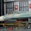
haneto Posted April 15, 2018 Share Posted April 15, 2018 (edited) Hi mates So long time no WIP thread since the ICM MiG-25RBT (yes I will finish it since I've got myself the amazing Amigo model resin nozzles), I'd like to start this thread to build a kit which was researched/designed by myself, as one of the development team member together with Gabor. This is the THIRD time I build this kit, but the first time to paint it. And I will build it as a modeller, not a developer to show all the tips you need to pay attention ahead, to make your all building much easier and more straight forward. Here we go with the upper fuselage part A3. First you need to add some putty to the 2 sides of nose where slight shrinkage could be found, because of the thick plastic with install pin holes there. Mask the rivets/details around to protect them from sending. The camera alike thing needs to be added since front part was obmit due to injection mold limitation. The rear edge of wings is way too thick. Be sure to thinner it. Now we are meeting the most headache part in the whole built. The nozzle padel ring part F2 is too big to meet the engine pods. I have no idea why this happened since I had no problem when assembling T1 version. I guess the tool factory added more details which increased the F2 part diameter. But of course it is NOT UNBUILDABLE just with some 10 min extra work. This is my solution. But the tail boom edge about 0.3mm (blue mark), both upper and lower fuselage. Then it should be like this. No worry about the hole here since it will be unvisible by nozzle padel part F2. And the F2 part fits much much better now. Now moves to lower fuselage part B3. Some raised panels need to be added. Drill holes ahead too. Diameter 0.7mm for 4 holes on nose, and 1.2mm for 6 holes on lower wings. Edited April 15, 2018 by haneto 11 Link to comment Share on other sites More sharing options...
haneto Posted April 15, 2018 Author Share Posted April 15, 2018 Go on with nozzles. Due to plastic part thickness, the nozzle rotation angle may not be big enough to satisfy us. But again, it could be SOLVED with very much simple work. For part F2, sand the inner ring to increase inner diameter. Cut the first raised ring on part D5 too. I also sanded the inner part of nozzle padels D10/11/12/13 so that the thickness is much improved to add sharpness. Now the parts are so good to replicate the real AL-41F nozzles. Then the intake/engine pod parts H1 and H2. Nothing special, you just need to cut the front/rear end of install pins by about 0.3mm, and the whole part will fit quite seamless with lower fuselage part B3, almost no gap. Next is vertical fins. Cut the little fresh inside of part B5. And also cut the install pin inside of part B8. There is a WRONG recessed panel line on part B4 by careless tool cutting. Fill and sand it to flat, add back the rivets. The small intakes fit not too well with vertical fins. Use putty and sand with care. All PLAAF Su-35SK obmit the GPS antennas which are on RusAF Su-35S, so I sand the detail off and add panel lines/rivets here. Attention: this change is ONLY for PLAAF version! Do NOT do this if you are building the Russian one. 10 Link to comment Share on other sites More sharing options...
haneto Posted April 15, 2018 Author Share Posted April 15, 2018 Then the cockpit parts. First the K-36D-5 seat. Sorry you have no choice since no other makers ever made this seat especially designed for Su-35 and Su-57 before, plastic or resin, so you have to use GWH plastic parts. But it's quite OK actually with some careful cleaning work, and also add the bulge on 2 sides of headrest. And if you prefer more fun to have the canopy swithing between open/close any time after finish, cut out the area on part C99 to avoid interfere with part C49. The front slat parts G4/5 and G7/8 need some sanding work and recribing/rivetting. I added needle tip on top of nosecone part G11, to add sharpness and strength. Next are weapon part. First the L-265M10 Khibiny-M ECM pods. The lift holes are molded all in the center of upper bulge, but actually the front lift hole is offsite to outer side. I remade the lift holes with 0.3mm brass rod, and open hole on small intake part I2 whicn is only on left ECM pod. There are issue with the cooperation between pylons and missiles I have summarized my solution to simplify your built. 7 Link to comment Share on other sites More sharing options...
haneto Posted April 15, 2018 Author Share Posted April 15, 2018 Final is the canopy. As you know in the first limit edition, you have one clear brown sprue to replicate the tint canopy. I send Tamiya 1/48 F-16CJ tint canopy part to factory as their reference to mix the right color. But unfortunately (just as other "expected" issues), the color was too light and they started mass production before obtaining my approval to catch the schedule. So for my own built, I decide to "tint" the canopy my self. I also used Future wax to improve the clear parts. Really super impressive! I coated the canopy by Gunze Creos Mr Color GX109 clear brown. Just Tamiya F-16 clear part sprue as the standard for color tone. To be continued... 12 2 Link to comment Share on other sites More sharing options...
Uncle Uncool Posted April 15, 2018 Share Posted April 15, 2018 Impressive work, Yufei, my mate! Will gladly follow yer thread. How did you place "they're" needle on the tip of the radome nose? Cheers, Unc2 Link to comment Share on other sites More sharing options...
rotaliscia Posted April 16, 2018 Share Posted April 16, 2018 (edited) I will follow with deep interest Haneto, toward the decision to buy the kit. I would take photos from a little behind. Subjects a bit smaller, I mean. Visibility and readability of the thread would improve a lot. Edited April 16, 2018 by rotaliscia Link to comment Share on other sites More sharing options...
matteo44 Posted April 18, 2018 Share Posted April 18, 2018 This WIP will be very interesting! I will follow it... Nice job Link to comment Share on other sites More sharing options...
haneto Posted May 1, 2018 Author Share Posted May 1, 2018 Thank you all for your encouragements guys! Yes I know these issues should have been fixed before releasing but we have to live in a imperfect world, and we have to face the fact. Fortunately noen of the issues is big deal so with a bit extra patience and dry fit, your build will be very much straight forward and enjoyable. Today is the labor day, a National holiday in China so finally I found some time to update the work. Some additional notes to vertical fin parts since some guys reported the right fin does not fit well with fuselage. I found the mounting slice was a bit too thick which is the main reason for the problem. Just thin 2 sides of the slice a bit and you will be happy. The left fin meanwhile, need no extra work to fit like a glove. 5 Link to comment Share on other sites More sharing options...
haneto Posted May 1, 2018 Author Share Posted May 1, 2018 This time I also tried mini magnet to enjoy more weapon configuration in the future. The Su-35S is a multi role fighter so most adaptors have same install structure to fit any missile pylons. Another reason is that I'd lik to enjoy the well researchd and fine details on belly, especially on central pylon mounting points. In order to assur enough holding strength, I added 4 magnetc per pylon. There is no need to add magnets on weapons since almost every Russian missile has its own pylon so you cannot exchange different missiles on different pylons. And you can make your weapon configuration freely at any time going forward! 10 Link to comment Share on other sites More sharing options...
haneto Posted May 1, 2018 Author Share Posted May 1, 2018 It cost me a whole day to add details/piping the landing gears yesterday, from 9:00 AM to 23:00 PM. It remineded me of my age...did not have such suffered experience when I made the 1/72 Su-27 about 10 years ago. The Flankre gear detailing is always a pain: too much complicated piping work! Although Su-35 piping is simplified compared with Su-27 or Su-30, thanks to the technology improvement I guess, it's still time consuming... Well another reason is too many references now. Very "negative" for serious modellers mental health I have to admit (just joking)! I used 2 diameter brass lines for piping, 0.1mm 0.2mm and 0.3mm All are very easy to bend and no nasty resilience. 10 Link to comment Share on other sites More sharing options...
haneto Posted May 1, 2018 Author Share Posted May 1, 2018 And these are the final result. Nose gear 9 Link to comment Share on other sites More sharing options...
haneto Posted May 1, 2018 Author Share Posted May 1, 2018 I replaced the plastic dischargers with Master metal ones. Those are definitely recommended! Actually the plastic dischargers on T1 sprues were only half diameter compared with current ones(mass production ver), but unfortunately they were too fragile to deal with so tool factory had to make them fatter. I also recommend you to deepen the rivets on radome part sides by 0.3mm drill. You can only find very shallow trace of the rivets there but you can use them as guide. The reason why those rivets are so shallow is due to injection mold technical limitation (the direction of pulling part out of mold). Now that all the hard/boring (in my personal opinion) work is finished, finally I can start my beloved painting job! To be continued... 8 Link to comment Share on other sites More sharing options...
Duncan B Posted May 1, 2018 Share Posted May 1, 2018 This is a great source of information for those of us who intend making this beautiful kit so I thank you for showing us. I really like the magnets for the weapons pylons, did you drill right through the lower fuselage/wing parts to fit the magnets? Duncan B Link to comment Share on other sites More sharing options...
exdraken Posted May 1, 2018 Share Posted May 1, 2018 Thank you for putting this here! Such a marveloud kit and still do heavily inproved! Link to comment Share on other sites More sharing options...
haneto Posted May 6, 2018 Author Share Posted May 6, 2018 Thanks for checking and from this weekend finally I can start painting this beast. I will paint most of the parts BEFORE assembling, and that's the purpose we made the parts arrangement. Most of parts have at least one gate which will be invisible after gluing, so you can keep that gate/sprue on the part for easier removing parting lines, painting and weathering. And that's why I tried to solve all the assembling issues before painting, for smoother assembling experience going forward. So as always I sprayed Gunze Creos #1500 surfacer on all parts, to check if the parting line has been removed thoroughly. And just as I said above, you can see I leave some sprue/one gate on some small parts especially those fragile pipes for easy handling and also sort of protection. To be continued... 12 Link to comment Share on other sites More sharing options...
Azgaron Posted May 6, 2018 Share Posted May 6, 2018 Excellent work! Love the attention to detail! Håkan Link to comment Share on other sites More sharing options...
redcap Posted May 6, 2018 Share Posted May 6, 2018 This information and advice will be absolutely invaluable to those of us who build this kit so 'Thank You' Haneto for sharing the great work you are doing with this kit. I just hope it builds (much) better than the GWH MIG 29 kits which looked great in the box but had some dreadful fit issues in some areas. Watching this one with great interest! Gary 2 Link to comment Share on other sites More sharing options...
matteo44 Posted May 10, 2018 Share Posted May 10, 2018 Fantastic job! The landing gears are perfect!! Congratulations Link to comment Share on other sites More sharing options...
Duncan B Posted May 10, 2018 Share Posted May 10, 2018 Seeing all those parts waiting to be painted is a real eye opener. I look forward to seeing how the painting goes. Duncan B Link to comment Share on other sites More sharing options...
haneto Posted May 21, 2018 Author Share Posted May 21, 2018 On 5/6/2018 at 6:44 PM, redcap said: This information and advice will be absolutely invaluable to those of us who build this kit so 'Thank You' Haneto for sharing the great work you are doing with this kit. I just hope it builds (much) better than the GWH MIG 29 kits which looked great in the box but had some dreadful fit issues in some areas. Watching this one with great interest! Gary Hi Gary This kit definitely fits much better than the Fulcrum. No worry! Thanks all for your following! After my visit to Shizuoka last weekend, I finally finished painting the first part, cockpit and rador. Since many colors on details were not added in the instruction sheet which was finished in just about 3 days, I added the color by studying real life pictures for your references. The color I used are all Gunze GSI Creos Mr Color lacquer paints. 4 Link to comment Share on other sites More sharing options...
haneto Posted May 21, 2018 Author Share Posted May 21, 2018 Frames in side the canopy. 6 Link to comment Share on other sites More sharing options...
haneto Posted May 21, 2018 Author Share Posted May 21, 2018 Cockpit assembled. 6 Link to comment Share on other sites More sharing options...
haneto Posted May 21, 2018 Author Share Posted May 21, 2018 K-36D-5 ejection seat, latest model of K-36 family. Now only used by Su-30SM, Su-35 and Su-57. 5 Link to comment Share on other sites More sharing options...
haneto Posted May 21, 2018 Author Share Posted May 21, 2018 The final effect of the whole cockpit. Totally out of box. Yes with some patience you can get that too! 8 Link to comment Share on other sites More sharing options...
haneto Posted May 21, 2018 Author Share Posted May 21, 2018 And what's inside of the canopy...... 9 Link to comment Share on other sites More sharing options...

Recommended Posts
Create an account or sign in to comment
You need to be a member in order to leave a comment
Create an account
Sign up for a new account in our community. It's easy!
Register a new accountSign in
Already have an account? Sign in here.
Sign In Now