Hamden Posted September 24, 2018 Share Posted September 24, 2018 Coming together now, really looking like a T21 Roger 1 Link to comment Share on other sites More sharing options...
TheBaron Posted September 24, 2018 Share Posted September 24, 2018 Good to see you working off those Canadian pancakes with some dedicated labour Terry! Splendid shape-working. 1 Link to comment Share on other sites More sharing options...
Aeronut Posted September 24, 2018 Share Posted September 24, 2018 The hole on the nose is not the ‘tow’ point it’s the receptacle for the ‘torpedo’ ballast weight which was only fitted when flown solo , (although I do have a photo of a VGS CO and CFI flying with the ballast fitted). The actual tow release was immediately in front of the wheel box. I’d advise caution in using the T21 at Old Sarum as a reference as its had its whole nose fabricated by the museum. It’s a good effort but it’s not quite correct. 1 Link to comment Share on other sites More sharing options...
Terry1954 Posted September 24, 2018 Author Share Posted September 24, 2018 2 hours ago, Hamden said: Coming together now, really looking like a T21 Roger Thanks Roger, still a way to go 1 hour ago, TheBaron said: Good to see you working off those Canadian pancakes with some dedicated labour Terry! Splendid shape-working. Thanks Tony. Still working on the shape, but the pancake residue seems to remain! 1 hour ago, Aeronut said: The hole on the nose is not the ‘tow’ point it’s the receptacle for the ‘torpedo’ ballast weight which was only fitted when flown solo , (although I do have a photo of a VGS CO and CFI flying with the ballast fitted). The actual tow release was immediately in front of the wheel box. I’d advise caution in using the T21 at Old Sarum as a reference as its had its whole nose fabricated by the museum. It’s a good effort but it’s not quite correct. Thanks. When I read your reply I remembered that's what it was. I did most of my gliding in the T31, and my T21 launches were always with an instructor. I had myself attached many towing cables to the T31, but never did any to the T21, so forgot where the attachment was I guess. I'm aware of the health warnings with the Sarum T21, so am checking against other references as much as I can. It was just so fortuitous to get so close the the "real" thing. Thanks again all for encouragement. Back to the hobby room shortly! Terry Link to comment Share on other sites More sharing options...
Martian Posted September 24, 2018 Share Posted September 24, 2018 Very impressive! There can't be much of the original it left by now! Martian 👽 1 Link to comment Share on other sites More sharing options...
Terry1954 Posted September 24, 2018 Author Share Posted September 24, 2018 1 minute ago, Martian Hale said: Very impressive! There can't be much of the original it left by now! Martian 👽 Thanks Martian. It is a bit like Triggers Broom! Terry Link to comment Share on other sites More sharing options...
bigbadbadge Posted September 24, 2018 Share Posted September 24, 2018 Wow Terry some great reprofiling this is looking fantastic. Keep up the good work All the best Chris 1 Link to comment Share on other sites More sharing options...
Terry1954 Posted September 25, 2018 Author Share Posted September 25, 2018 9 hours ago, bigbadbadge said: Wow Terry some great reprofiling this is looking fantastic. Keep up the good work All the best Chris Thanks Chris. A little more progress last night. Will post more updates later today. Terry Link to comment Share on other sites More sharing options...
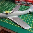
Terry1954 Posted September 25, 2018 Author Share Posted September 25, 2018 Last nights work involved producing a neat hole in the front of the nose, like this............ Then I needed to make the short stumpy tubular insert to pop inside. I used a suitable piece of plastic tube, which was subsequently "reamed" out a bit to make the sides a more realistic thickness. Popped inside and a bit of very fine liquid glue from Tamiya's finest and we get something that looks fairly true to lots of pictures I have looked at. Now that its well dry, I plan to sand that back so that it only protrudes just enough to look like the real thing. Then I have to focus on the underneath in this area. The good old T31 had two cable attachment points, one on the extreme tip of the nose, and one under the fuselage offset to one side (because of the skid). I believe this was due to it being a tandem seat aircraft, and depending on single or double occupancy, C of G could shift for and aft, thus needing a different attachment point. T31 experts out there are welcome to comment/confirm? You can see this on my T 31 below (under nose view) With the Sedbergh being twin side by side, the C of G for and aft shift was not an issue (I assume), so I believe there is only one attachment point needed? The picture below is from the Sarum aircraft, and given some of the comments around accuracy of the nose of this one, I'm reluctant to assume this attachment point is shown correctly. I also have another picture kindly provided by @stringbag which shows the attachment point in the same position. All looks good I think! The Sarum Machine Chris's picture So now need to refine the ballast hole (and work out if fitting that horizontal pin is feasible in this scale), create a square hole underneath for the cable attachment, and sort out that skid with its small wheels and the main wheel. I don't suppose anyone has a really detailed picture of what's up inside that square cable attachment recess? Thanks Terry 2 Link to comment Share on other sites More sharing options...
perdu Posted September 25, 2018 Share Posted September 25, 2018 I remember shoving the loop/ring up into the recess and pushing kinda BACK to clear the latch But no way could I sketch the arrangement for you after fifty five plus years Does stringbag have any drawings? Would an email to Kirkby Lonsdale*** get you the answer? Is Slingsby even still there at KL? So many questions, so have another When you get the answer will you risk harming the T31 to 'fix' it? Do not do that, step away from the fuse wire! ***ALERT ignore the idiot who wrote Kirkby Lonsdale I meant Kirbymoorside 😠 I don't know why I forgot, I've been there to watch them being built Sorry 1 Link to comment Share on other sites More sharing options...
Biggles87 Posted September 25, 2018 Share Posted September 25, 2018 Coming on really well. The front attachment point on the T31 was used for aeotows only. The idea of pushing the ring back to attach the cable was that you were checking the ' back release ' which was designed to release the cable if you flew past the winch ( I know someone it happened to but that's another story ) Sometimes, especially in winter you would be asked by the person attaching the cable to open the release so that they didn't have to get right down to do it, I never complied, and most other instructors didn't either because it was bypassing a safety check. John 1 1 Link to comment Share on other sites More sharing options...
keefr22 Posted September 25, 2018 Share Posted September 25, 2018 Nice work Terry she's looking really good. Keith 1 Link to comment Share on other sites More sharing options...
Terry1954 Posted September 25, 2018 Author Share Posted September 25, 2018 1 hour ago, perdu said: When you get the answer will you risk harming the T31 to 'fix' it? The T31 is fine in terms of shape of attachment points, so they don't need to be re-worked, however I have trawled through my RAF museum pics and realise that the second attachment point further back is on the wrong side! 😲 Maybe I should just keep quiet about that 🤐 What will need doing on the T21 is to make a square hole underneath and put some gubbins inside to replicate the real thing ............ assuming I can find out what it looks like. Probably not dissimilar to the above pic. I'll wait and see if anyone has any info for now, but meantime I will make a small square hole with my special square hole drill 🤔 Terry 2 Link to comment Share on other sites More sharing options...
Terry1954 Posted September 25, 2018 Author Share Posted September 25, 2018 1 hour ago, Biggles87 said: Coming on really well. The front attachment point on the T31 was used for aeotows only. The idea of pushing the ring back to attach the cable was that you were checking the ' back release ' which was designed to release the cable if you flew past the winch ( I know someone it happened to but that's another story ) Sometimes, especially in winter you would be asked by the person attaching the cable to open the release so that they didn't have to get right down to do it, I never complied, and most other instructors didn't either because it was bypassing a safety check. John Thanks John. Yes that was it aerotows! We always had winch tows so now I recall that it was always the one underneath, not the front. As you can see from the above, I have it on the wrong side on my T31. I can even now recall getting down under from the port side and attaching, never the other side. I guess I just blindly used the hole where Phoenix had put it, on the port side in the kit. I know it will anoy me, so may have to fix that one day! Terry Link to comment Share on other sites More sharing options...
perdu Posted September 25, 2018 Share Posted September 25, 2018 The attachment looks right for both to me In 72th-ness-ness scale a blob in the hole and a ring around it will more than suffice 1 Link to comment Share on other sites More sharing options...
stringbag Posted September 25, 2018 Share Posted September 25, 2018 On 9/24/2018 at 8:03 PM, Aeronut said: The actual tow release was immediately in front of the wheel box. Only if modified. The standard hook position is immediately in front of the front skid mounting bracket. This "compromise" hook position was seen to be the best position for both winch and aero-tow launches. Many have since been modified to move the hook rearwards to give better winch launches as it enables a steeper attitude during the climb without the need for constant back pressure on the stick and gives greater elevator authority. Chris 2 Link to comment Share on other sites More sharing options...
Terry1954 Posted September 25, 2018 Author Share Posted September 25, 2018 14 minutes ago, stringbag said: Only if modified. The standard hook position is immediately in front of the front skid mounting bracket. This "compromise" hook position was seen to be the best position for both winch and aero-tow launches. Many have since been modified to move the hook rearwards to give better winch launches as it enables a steeper attitude during the climb without the need for constant back pressure on the stick and gives greater elevator authority. Chris Thanks Chris. I saw from a few pictures of original Sedbergh's and can vaguely recall myself, the position in front of the skid as you describe. I've modelled that today, pics to follow soon! Terry Link to comment Share on other sites More sharing options...
Terry1954 Posted September 26, 2018 Author Share Posted September 26, 2018 As promised, pictures of what's going on underneath the nose. I managed to drill a square hole for the cable attachment! Actually it started as a small round hole, and then a very sharp new pointed scalpel blade was used to shape the corners. I'm quite proud of my small square hole! Below that are two areas that I have filed away to take the small "wheels" that will support the skid: The "wheels" for the skid have been made from plastic rod, drilled out a bit on either side. They are pretty small! The skid itself will be made from some laminated 5 thou which will form a shallow curve from the inky line you can see back to just behind the rear skid wheel, ahead of the main wheel. I will need to put in a couple of very small shims of plastic card on which to sit the skid wheels. Hope that makes sense. Finally I also added a small fillet of plastic card ahead of the fin, to represent the same on the real thing. This needs more work to blend in etc. Lots of fiddly detail to get right at the moment, but we are making progress I think! More tomorrow Terry 5 Link to comment Share on other sites More sharing options...
keefr22 Posted September 27, 2018 Share Posted September 27, 2018 8 hours ago, Terry1954 said: I'm quite proud of my small square hole! And so you should be, it's a very neat small square hole! Very neat work all round Terry! Keith 1 Link to comment Share on other sites More sharing options...
Hamden Posted September 27, 2018 Share Posted September 27, 2018 The link below may be of some interest https://forum.keypublishing.com/forum/historic-aviation/105553-t-21-restoration Roger 1 Link to comment Share on other sites More sharing options...
Terry1954 Posted September 27, 2018 Author Share Posted September 27, 2018 4 hours ago, keefr22 said: And so you should be, it's a very neat small square hole! Very neat work all round Terry! Keith Thanks Keith. Focusing on the skid work at the moment! More pics soon 56 minutes ago, Hamden said: The link below may be of some interest https://forum.keypublishing.com/forum/historic-aviation/105553-t-21-restoration Roger Thanks Roger. That link leads to some very extensive dialogue and pics which I will read thoroughly later on. From the parts I quickly looked at there are really useful pictures too. Terry Link to comment Share on other sites More sharing options...
perdu Posted September 27, 2018 Share Posted September 27, 2018 Looks very good but I wondered about skid wheels cos they look like solid round silentbloc shock absorbers and simply squished up and down when we all slammed down hard on to them But that is me just being 'picky stupid', overall the work you have done on this and the 31 are as good as scratchbuilding them from sheet placky Terry I love 'em Oh arr, nice hole 😊 you know what I mean 1 1 Link to comment Share on other sites More sharing options...
Terry1954 Posted September 27, 2018 Author Share Posted September 27, 2018 7 hours ago, perdu said: Looks very good but I wondered about skid wheels cos they look like solid round silentbloc shock absorbers and simply squished up and down when we all slammed down hard on to them But that is me just being 'picky stupid', overall the work you have done on this and the 31 are as good as scratchbuilding them from sheet placky Terry I love 'em Oh arr, nice hole 😊 you know what I mean Yes they are bendy kind of round shock absorbers, so am hoping to get that look. Appreciate the view on the work done so far. The T31 was and this one is, a bit like scratch building from sheet! Glad you like them. I am determined to get this one, and the RAF Sabre (very little done since returning from Canada), compete for Telford, so you will get to see the two gliders in the wood and fabric flesh! Having a night off from building this evening, partly due to some great wine we are indulging in tonight! More soon. Terry 1 Link to comment Share on other sites More sharing options...
keefr22 Posted September 28, 2018 Share Posted September 28, 2018 10 hours ago, Terry1954 said: Having a night off from building this evening, partly due to some great wine we are indulging in tonight! Good idea to leave the scalpels and other sharp implements alone then Terry! Looking forward to seeing them at Telford (the gliders that is, not the scalpels etc...!!) Keith 2 Link to comment Share on other sites More sharing options...
Terry1954 Posted September 30, 2018 Author Share Posted September 30, 2018 A little more progress today, involving the fabrication of the skid supports. No 3 Scalpel shown for scale. The idea is that the small "wheel" support blocks fit in like so. In the end I made four of the blocks as two of them went flying across the hobby room into the unknown............ And then, whilst I was working on the main wheel being held in my mini drill while I reduced the profile a bit, that too went flying. I searched for ages but didn't find it so I had to source another wheel, this one from a very old Hasegawa F-86 Sabre I think. I needed to re-profile that a bit and this time I drilled out the centre hub and fixed it to a small mandrel to be held more firmly in the mini drill. The mandrel hole had to be quite large, so the hub was re-instated with a bit of black plastic rod. Test fit into the underside. The wheel supports each side will be made up from plastic card as indicated in the second picture. And the last thing I wanted to do to the main wheel was to add a bit of detail around the rim on each side. Thats all for tonight. Terry 4 Link to comment Share on other sites More sharing options...

Recommended Posts
Create an account or sign in to comment
You need to be a member in order to leave a comment
Create an account
Sign up for a new account in our community. It's easy!
Register a new accountSign in
Already have an account? Sign in here.
Sign In Now