Terry1954 Posted March 17, 2018 Share Posted March 17, 2018 So having tested the water with a couple of RFI's here, I thought I'd take the plunge and start my first WIP. Its a Vacform 1/72 T21 by Phoenix models. Like my T31 I posted in RFI a few weeks back, this is another aircraft that I spent some happy years experiencing the joys of flight as a teenager, with 615 Gliding school at RAF Kenley. As you can see, although basic, they are probably all that could be offered for such a kit. Thanks to some very helpful information from Chris @stringbag I also have some plans from an old edition of the Aeroplane. The plans appear very accurate and are ideal for working on this model in this scale. Thanks again Chris! So a start has been made on separating (almost) all the parts from the main sheet..... The first thing I plan to tackle is the wing which I think will be the biggest challenge. As Chris pointed out and the plans confirm, there are two stages of dihedral on the undersurface, but the top surface of each wing out from the centre is perfectly flat, with just a small amount of dihedral at the centre point. I decided to use some brass strip to help form this, which enabled me to produce a plastic spar (both seen below). The brass is very rigid and was bent in a small vice at the three points along the wing. The plastic spar was then assembled against the brass with superglue joins. The next stage will be to modify the plastic spar such that the outer two sections are flat across the top, but retain the anhedral underneath. At the moment this is a trail and error idea. I may end up having to produce some internal wing ribs as there appears to be some under camber on the lower wing. I cant promise this WIP will be quick, but it might be interesting watching me grapple with this thing and my ideas! Stay tuned if you are interested! Cheers Terry 13 Link to comment Share on other sites More sharing options...
Hamden Posted March 17, 2018 Share Posted March 17, 2018 I'll follow along I to flew in the T21 as an Air Cadet from Old Sarum nr Salisbury. Looks like the wing will be a great challenge and I look forward to watching this progress. Roger 3 Link to comment Share on other sites More sharing options...
Terry1954 Posted March 17, 2018 Author Share Posted March 17, 2018 19 minutes ago, Hamden said: I'll follow along I to flew in the T21 as an Air Cadet from Old Sarum nr Salisbury. Looks like the wing will be a great challenge and I look forward to watching this progress. Roger Hi Roger, I know Old Sarum well, I did some of my PPL training there. I see you are in Dorchester. I'm down the road near Swanage. Yes that wing has got the brain cells going a bit! Terry 2 Link to comment Share on other sites More sharing options...
Terry1954 Posted March 17, 2018 Author Share Posted March 17, 2018 Another shot showing fuselage halves and the challenges of working with very thin vac form shapes ...... I managed to crack the one on the left, hence the super glue repair and some Mr Surfacer work! 5 Link to comment Share on other sites More sharing options...
perdu Posted March 17, 2018 Share Posted March 17, 2018 All clear, above and behind All out! Cue the V8 revving up and the madcap dash to the runway at Colerne, my first T21 sorties behind a cutaway Ford Pilot 3 Link to comment Share on other sites More sharing options...
Terry1954 Posted March 17, 2018 Author Share Posted March 17, 2018 6 minutes ago, perdu said: All clear, above and behind All out! Cue the V8 revving up and the madcap dash to the runway at Colerne, my first T21 sorties behind a cutaway Ford Pilot Surely you didn't forget ....... "Take up slack"! 2 Link to comment Share on other sites More sharing options...
perdu Posted March 17, 2018 Share Posted March 17, 2018 (edited) Fifty five years Yes forgot the middle of the sequence Didn't forget the bollyking for not making it obvious enough to the pilot that I had looked above and behind... 😬 Edited March 17, 2018 by perdu 3 Link to comment Share on other sites More sharing options...
Terry1954 Posted March 17, 2018 Author Share Posted March 17, 2018 Yes a long time ago for me also, almost 50 from my first flight in a T21. The bollykings seemed a constant and standard part of a typical days flying. I recall hearing shouts (from the ground), from an instructor, to a friend of mine flying above us in a T31 "...... when I said turn laddie, I didn't mean turn on a f*****g sixpence". It was an amusingly tight turn to watch though! 1 3 Link to comment Share on other sites More sharing options...
Brandy Posted March 17, 2018 Share Posted March 17, 2018 Ahh, happy memories! I too had a few flights in these, mainly from Halton, although I did my glider course at Newton in the Venture. I'll be watching from the bar! Ian 4 Link to comment Share on other sites More sharing options...
Terry1954 Posted March 17, 2018 Author Share Posted March 17, 2018 Well I spent a little time thinking about the wing spar. I need to shave/file/sand/cut off the black portion in the picture. This makes sure that the upper part of each wing has no dihedral, and the lower part has double dihedral. After shaving/cutting/filing/sanding we are left with this.................. Each picture only shows one half of the whole spar. Have to do similar to both ends of the whole spar. I'm not sure how well this will work as although the spar is made of square plastic around 2mm square, it may require some beefing up on the vertical (front and rear) edges .......... if that makes sense! Regarding the top and bottom wing parts themselves, I'm also considering cutting the top wing part in the centre, to achieve the dihedral there, and the lower wing part into four. all six pieces then go onto top and bottom of spar. Anyone having any better ideas, please let me know! I'll try and produce a picture as this may not make sense! Terry 5 Link to comment Share on other sites More sharing options...
stringbag Posted March 17, 2018 Share Posted March 17, 2018 Hi Terry. The term double dihedral might be a bit misleading here. There is only a single dihedral angle measured along the top surface of the spar. The wing has a constant chord, thickness and section from the root end out as far as the inboard aileron. From there outboard, the section and thickness changes. Give me a call if You need any further info. Looking forward to this one progressing. Chris. 1 1 Link to comment Share on other sites More sharing options...
Terry1954 Posted March 18, 2018 Author Share Posted March 18, 2018 10 hours ago, stringbag said: Hi Terry. The term double dihedral might be a bit misleading here. There is only a single dihedral angle measured along the top surface of the spar. The wing has a constant chord, thickness and section from the root end out as far as the inboard aileron. From there outboard, the section and thickness changes. Give me a call if You need any further info. Looking forward to this one progressing. Chris. Hi Chris, Yes you are correct, its a bit misleading calling it double dihedral. I think I get the whole geometry of the wing from your descriptions and the plan. I'll post some pics later to show how I'm tackling it. I may even be able to build in some slight under camber ........... Thanks again Terry 1 Link to comment Share on other sites More sharing options...
Martian Posted March 18, 2018 Share Posted March 18, 2018 This looks fun, I'm in! Martian 1 1 Link to comment Share on other sites More sharing options...
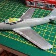
Terry1954 Posted March 18, 2018 Author Share Posted March 18, 2018 The latest pics showing slow progress. I have several other models on the go, one of which I will also RFI here soon. I have completed the spar and its glued into the top wing half. it has very slight dihedral from the mid point of the wing, but then runs straight out to the tip. This one shows (I hope) that better ....... what do you think @stringbag ? The trickier part will be the lower wing. I decided to do that in three parts, the centre section where there is constant chord, then each underside outer part as the undersurface slopes very slightly upwards as they run to each wing tip. I've yet to stick the centre underside wing onto the top as I want to build in the very slight under camber towards the trailing edge. Similarly with the lower outer parts. I want to achieve the thin trailing edge so I think trimming the trailing edges of the underwing sections at the rear will help achieve this. This picture shows part of the plan I'm working with which has been immensely helpful. Credit here please to @stringbag Advice/Ideas/Inspiration welcome! I think I'll start another RFI on my long in production Avon Sabre now, that ones close to completion! Thanks Terry 5 Link to comment Share on other sites More sharing options...
stringbag Posted March 18, 2018 Share Posted March 18, 2018 1 hour ago, Terry1954 said: This one shows (I hope) that better ....... what do you think @stringbag ? I want to build in the very slight under camber towards the trailing edge. Terry Hi Terry. Looks to me from that picture that you have pretty much got it sorted as far as the upper surfaces are concerned. Fitting the lower surfaces in two halves is probably the best way to achieve the taper change on the lower section. As far as the under-camber is concerned, could you not make a series of ribs to the correct wing section. At least one at the root end , one at the spoiler position where the plywood area is located on the original and one at the inboard end of the aileron? It should be a relatively straightforward process as they would all be the same shape within that area, The ribs could be fixed initially to the inside of the top surfaces and then the lower surfaces could then be attached after the trailing edges have been thinned down as much as possible. Definitely worth a try as the under-camber and relatively thick wing at the main spar position are characteristics that really stand out on the T21. I will send you some more pics over to your e-mail address if they will help. Feel free to post them here if you wish. Hope this helps. Chris. EDIT. I meant to add that the upper sections of the wing in your photograph look very good indeed. Much better than any other example I've seen even in the larger scales, including resin kits. 1 1 Link to comment Share on other sites More sharing options...
Terry1954 Posted March 18, 2018 Author Share Posted March 18, 2018 34 minutes ago, stringbag said: Hi Terry. Looks to me from that picture that you have pretty much got it sorted as far as the upper surfaces are concerned. Fitting the lower surfaces in two halves is probably the best way to achieve the taper change on the lower section. As far as the under-camber is concerned, could you not make a series of ribs to the correct wing section. At least one at the root end , one at the spoiler position where the plywood area is located on the original and one at the inboard end of the aileron? It should be a relatively straightforward process as they would all be the same shape within that area, The ribs could be fixed initially to the inside of the top surfaces and then the lower surfaces could then be attached after the trailing edges have been thinned down as much as possible. Definitely worth a try as the under-camber and relatively thick wing at the main spar position are characteristics that really stand out on the T21. I will send you some more pics over to your e-mail address if they will help. Feel free to post them here if you wish. Hope this helps. Chris. EDIT. I meant to add that the upper sections of the wing in your photograph look very good indeed. Much better than any other example I've seen even in the larger scales, including resin kits. Hi Chris, Thanks for this. I'm going to work through a couple of ideas for the under-camber, yours sounds quite good actually. Will post more pics as ideas evolve. I'm splitting this workload with another WIP on a 1/72 Avon Sabre conversion which is nearing completion, so thats a bit of light relief from this one! Cheers Terry Link to comment Share on other sites More sharing options...
Terry1954 Posted March 18, 2018 Author Share Posted March 18, 2018 I decided to cut the lower surface of the wing into four I have also cut a few mm from the trailing edge of the centre two sections. This is to help with the trailing edge thickness (needs to be thinner). I'll deal with the outer trailing edges differently. Ive also put some curvature into the parts. This view shows one of the centre parts being held in place. Note it falls short of the trainling edge as intended. This will be clamped in tight and help to form the under-camber ...... well thats the plan! A quick shot of a test fit of one of the outer lower wing panels This shot shows that I have been able to apply some curvature to the centre wing panel using a stainless steel rod of suitable diameter and finger pressure. I think thats me done for tonight, a cold beer is calling! Cheers Terry 4 Link to comment Share on other sites More sharing options...
Terry1954 Posted March 19, 2018 Author Share Posted March 19, 2018 A little more progress today. Started to glue the lower centre wing panels to the upper wing. The clamping is to pull the trailing edge down to create some under-camber. I used quick set superglue. When those were set I glued the leading edge part and clamped those also. The solid plastic spar helped to maintain the aerofoil shape which I think you can see in this shots.... Finally for tonight, I used some quick set putty (green stuff) to fill in the gap between trailing edge of of the shortened chord bottom wing parts and the main trailing edge of the upper wing. This will need sanding to maintain aerofoil shape and keep trailing edge very thin. You can see this below. The two outer lower panels are shown also. I plan to attach these after getting the main aerofoil part to a reasonable finish. Thats enough on this one for one evening for me. Cheers Terry 3 Link to comment Share on other sites More sharing options...
stringbag Posted March 19, 2018 Share Posted March 19, 2018 That's a big improvement Terry. Do you intend to separate the control surfaces? Well worth doing in my humble opinion as they were rarely seen in the neutral position, and there was usually quite a noticeable hinge gap unless someone went to the trouble of sealing the gaps with fabric and even then the gaps were noticeable. I forgot to ask what colour scheme it will finally wear. Civil or military? Chris. 1 Link to comment Share on other sites More sharing options...
Terry1954 Posted March 19, 2018 Author Share Posted March 19, 2018 8 minutes ago, stringbag said: That's a big improvement Terry. Do you intend to separate the control surfaces? Well worth doing in my humble opinion as they were rarely seen in the neutral position, and there was usually quite a noticeable hinge gap unless someone went to the trouble of sealing the gaps with fabric and even then the gaps were noticeable. I forgot to ask what colour scheme it will finally wear. Civil or military? Chris. Thanks Chris, Just sent you an email, spooky! Yes I was thinking of separating the control surfaces. I think that would look good, and will also help actually with achieving the subtle under-camber. I'm planning a military scheme again, very similar to the T31, silver dope and dayglo bands. I'd like to model one that I flew in at 615 Gliding school you see. I was slightly tempted to do the slightly later scheme of red/white, but we'll see. Cheers Terry Link to comment Share on other sites More sharing options...
stringbag Posted March 19, 2018 Share Posted March 19, 2018 Just answered . Don't forget that the undercamber reduces from the taper change until the section is almost flat at the tip. It will probably be easier to cut the ailerons out after the bottom surfaces have been attached so that the correct thickness is achieved at the aileron spar. The gap (between upper and lower surfaces) can then be filled in with some scrap strip and some holes drilled to accept wire hinges. Making good progress on this I must say. Chris. Link to comment Share on other sites More sharing options...
Terry1954 Posted March 21, 2018 Author Share Posted March 21, 2018 Well lots of work on this over the last couple of days but it feels like slow progress! Firstly the wings............ Sanding and smoothing Then some Mister Surfacer to get a finer finish. Also in these pictures you will see a section of square plastic rod. This has been superglued in as an additional safeguard to strengthen the centre and dihedral which was reliant on a single spar, which had shown signs of weakness at the wing centre section. Needed to make sure the wings didn't snap in half later on. It seemed to do the job. Then I decided to attach the port outer underside wing panel. This involved much clamping/holding together to make sure the edges held and the under camber continued at least into the outer panel, but not all the way to the tip. First is view from top Then bottom rear .... Then bottom front......... I decided to leave the starboard wing till next time to give this one time to set. So the next task this evening and by way of a change, I decided to do some work on the cockpit. Stay tuned and I'll post some of that work shortly... Cheers Terry 6 Link to comment Share on other sites More sharing options...
stringbag Posted March 21, 2018 Share Posted March 21, 2018 Coming together nicely Terry. 1 Link to comment Share on other sites More sharing options...
Terry1954 Posted March 21, 2018 Author Share Posted March 21, 2018 OK, so this is what I've been doing in the cockpit. The instrument panel supplied looks very good as far as instrument panels go but ............... its nothing like the real thing! So I'm having a go at scratch building that. Top one is as supplied, lower is start of scratch build The lower panel needs an instrument plate So this is first attempt. There are two instruments on the left, a variometer next to those and a third instrument on the right. All very small in this scale ... There are a couple of cut outs, that I can best describe as "glove compartments". I'm sure @stringbag can enlighten us here.... Not stuck together yet. Not sure whether I'm happy with this yet. Will sleep on that one. Then we have the cockpit floor and rear bulkhead. I'm using this as supplied, but I have added the centre "console" which sits between student and instructor. From memory this houses the spoiler lever. For those not used to gliding this (was then) a lever which operated two overwing upward hinging flaps, which literally "spoiled the airflow. The net result was a much reduced lift capacity, and scary and sudden height loss! The square hole in the middle enables the two joy sticks to be linked by a metal bar. I think the control cable runs then run back under the console. Again, Chris will I am sure verify or correct all this technical garb! Need to think about seats, which are supplied, but not convinced of accuracy. Time for alcohol I think! Cheers Terry 5 Link to comment Share on other sites More sharing options...
stringbag Posted March 21, 2018 Share Posted March 21, 2018 Hi Terry. One of the compartments in the front panel was to house a battery to drive the T/S indicator. Usually covered over with a ply-wood plate. In all of the T21's in my log book, I've never yet found one that was actually connected up. The other was normally open and could indeed be used for gloves or goggles. The centre console between the seats supports the spoiler lever and associated cables, together with the rudder cabled which are fixed to the inboard pedal on both sides. The ailerons and elevator torque tube is also housed in the centre console. Chris 1 2 Link to comment Share on other sites More sharing options...

Recommended Posts
Create an account or sign in to comment
You need to be a member in order to leave a comment
Create an account
Sign up for a new account in our community. It's easy!
Register a new accountSign in
Already have an account? Sign in here.
Sign In Now