Gene K Posted January 17, 2018 Share Posted January 17, 2018 18 hours ago, rob Lyttle said: Found a picture in a book -(how quaintly old fashioned am I?!) that might help for ailerons. Showing Red internals. Only on the initial test aircraft! Gene K 1 1 Link to comment Share on other sites More sharing options...
giemme Posted January 17, 2018 Author Share Posted January 17, 2018 2 hours ago, massimo said: Great start Giorgio!!! I love all the work you've done to match the resin cockpit to the fuselage halves!!! That cannon housing is simply outstanding!!! Cheers Massimo, thank you 1 hour ago, boom175 said: 31 Years between the Engine shop, Flight line (Crew Chief) and being the base Engine Manager. Still miss working on them!! Any questions you have please ask. Wow, that's a long time! I will ask a few questions about painting for the moment, if you don't mind: the kit instructions call for white for the U/C bays and while looking at walkarounds of the A-10A in Euro 1 scheme, they all look more a light grey to me. Can you shed some light here? Also, what would be the color for the inside of the retractable ladder bay and for the avionics bay? TIA Ciao Link to comment Share on other sites More sharing options...
giemme Posted January 17, 2018 Author Share Posted January 17, 2018 1 hour ago, Gene K said: Only on the initial test aircraft! Gene K Thanks! @boom175 cleared that up, too. Ciao Link to comment Share on other sites More sharing options...
boom175 Posted January 17, 2018 Share Posted January 17, 2018 9 minutes ago, giemme said: Wow, that's a long time! I will ask a few questions about painting for the moment, if you don't mind: the kit instructions call for white for the U/C bays and while looking at walkarounds of the A-10A in Euro 1 scheme, they all look more a light grey to me. Can you shed some light here? Also, what would be the color for the inside of the retractable ladder bay and for the avionics bay? TIA Ciao When they were Euro one camo, the wheel wells and actually the struts of the landing gear were "ADC Grey" FS 16473. As well as the interior of the ladder door well and the inside of the door itself. All the avionics bays were 16473 same as the inside of the panels. 2 3 Link to comment Share on other sites More sharing options...
giemme Posted January 17, 2018 Author Share Posted January 17, 2018 39 minutes ago, boom175 said: When they were Euro one camo, the wheel wells and actually the struts of the landing gear were "ADC Grey" FS 16473. As well as the interior of the ladder door well and the inside of the door itself. All the avionics bays were 16473 same as the inside of the panels. Excellent, thanks for sharing Ciao Link to comment Share on other sites More sharing options...
Gene K Posted January 18, 2018 Share Posted January 18, 2018 (edited) 22 hours ago, boom175 said: 31 Years between the Engine shop, Flight line (Crew Chief) and being the base Engine Manager. Great that you're here "boom", to keep everything in order!! All your time at Warfield ANG Base? I do have a question (for starters): Where is the transducer that actuates the slats -- the one that the crew chief operates during checks? Gene K Edited January 18, 2018 by Gene K Link to comment Share on other sites More sharing options...
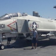
giemme Posted January 20, 2018 Author Share Posted January 20, 2018 I have a couple of questions too for those "in the know": what are these sensors on the nose? and this pod underneath the nose? Looking at various pics, it looks like they are not present together, and I even saw one pic (of an A-10C though) in which both were missing. The first one I just posted it's of the airframe I'm modelling, but I haven't got a starboard side view to check if that pod was there. Bottom line, the kit has the pod but not the sensors, so I'm just trying to figure if I only need to add them or I also need to remove the pod. TIA Ciao 1 Link to comment Share on other sites More sharing options...
Corsairfoxfouruncle Posted January 20, 2018 Share Posted January 20, 2018 (edited) @giemme ... I believe they're Different radar warning recievers for Sam launches. The block replaced the dot version if im not mistaken ? The eyeball/dot system was created during, and upgraded after Vietnam in the ‘70 s and early’80’s. The block style came on in the ‘80’s or maybe early ‘90’s. I think they've been changed again since the current fracas in the sandboxes has been going on. Edited January 20, 2018 by Corsairfoxfouruncle 1 Link to comment Share on other sites More sharing options...
Gene K Posted January 20, 2018 Share Posted January 20, 2018 1 hour ago, giemme said: I have a couple of questions too for those "in the know": what are these sensors on the nose? I'm not really "in the know", but ... AN/ALR-46 . See this link for a quickie visual (use "translate"). Note the additional antennae for the AN/ALR-64, so depends on the airframe you are modelling as to what is showing. Also some good stuff in this multi part series here as regards other early/late mods. I'm sure the experts will be able to help!! Gene K 1 Link to comment Share on other sites More sharing options...
rob Lyttle Posted January 20, 2018 Share Posted January 20, 2018 Sorry to be giving you the trivial answer.... they do make great nostrils, don't they? That plane in the second pic just doesn't look complete! Link to comment Share on other sites More sharing options...
giemme Posted January 20, 2018 Author Share Posted January 20, 2018 4 hours ago, Corsairfoxfouruncle said: @giemme ... I believe they're Different radar warning recievers for Sam launches. The block replaced the dot version if im not mistaken ? The eyeball/dot system was created during, and upgraded after Vietnam in the ‘70 s and early’80’s. The block style came on in the ‘80’s or maybe early ‘90’s. I think they've been changed again since the current fracas in the sandboxes has been going on. 3 hours ago, Gene K said: I'm not really "in the know", but ... AN/ALR-46 . See this link for a quickie visual (use "translate"). Note the additional antennae for the AN/ALR-64, so depends on the airframe you are modelling as to what is showing. Also some good stuff in this multi part series here as regards other early/late mods. I'm sure the experts will be able to help!! Gene K Thanks both So, reading through Gene's links, if I want to reproduce a Gulf war era aircraft, it looks like I need to remove both the box radar warning receivers and put the dot ones on the nose and tail. 1 hour ago, rob Lyttle said: Sorry to be giving you the trivial answer.... they do make great nostrils, don't they? That plane in the second pic just doesn't look complete! They do And the picture I have of the aircraft I'm modelling shows them, luckily Ciao Link to comment Share on other sites More sharing options...
boom175 Posted January 20, 2018 Share Posted January 20, 2018 On 1/18/2018 at 11:21 AM, Gene K said: Great that you're here "boom", to keep everything in order!! All your time at Warfield ANG Base? I do have a question (for starters): Where is the transducer that actuates the slats -- the one that the crew chief operates during checks? Gene K Yep! Thats where I was! The transducer is just out board of the L/H MLG sponson or "pod" it is pretty small probably 2"X2" its unpainted as it is a heated surface (it comes on when the pilot selects pitot heat ) 1 Link to comment Share on other sites More sharing options...
S5 modeller Posted January 21, 2018 Share Posted January 21, 2018 (edited) On 17/01/2018 at 12:36 AM, rob Lyttle said: Is there any kit or A M version of the ammo loading apparatus that's used to service the monster? It's pretty unique, and would make a great add-on. PS. I'm sure you've sussed it already, but go maximum with nose- weight. You could well be dealing with the most tail-sitting model airframe of them all. Flight path do an etch dragon reloaded.... https://www.djparkins.com/product.php?productid=17777&cat=252&page=1 It's 1/48 though. Brilliant work giemme. I can't wait to see the finished results. Matt Edited January 21, 2018 by S5 modeller 2 Link to comment Share on other sites More sharing options...
giemme Posted January 21, 2018 Author Share Posted January 21, 2018 Cheers Matt, thank you I don't think I'll attempt a diorama, right now I'm leaning towards a parked aircraft with open canopy, deployed boarding ladder, open avionics bay (but I haven't found a close up pic of that yet) and RBF tags. Before taking the final decision, however, I still have to investigate the feasibility of moving the moveable parts and finding a crew chief figure - which would also mean I have to think of a suitable base. Ciao 3 Link to comment Share on other sites More sharing options...
Sting67 Posted January 21, 2018 Share Posted January 21, 2018 (edited) Hello all. I'm a newly registered member here but followed this forum with high interest for a long time as a reading guest. But now it was time to register here, partly because you giemme started building a project I currently have at my workbench. (I'm building a unit of the 74th TFS that also took part in Op. Desert Storm). I have been collecting photos and information about the A-10 und its EL units like crazy. As I have been following this thread, I have noticed that here and there emerged questions. Or there are infos that could be helpful for a optimum result. Did you know this resource? Link Very important information, because often the infos in books are vague and sometimes they even contradict each other. I believe that this loadout scheme is very credible as it underlines pictures of the real thing: Link Look at the bottom of the drawings: Link Another important thing: Compare the color scheme on the Italeri instructions sheet of the unit your are building with the real thing. Italeri says that these colors will be needed: FS34082, FS36118 and FS34102. The European 1 scheme on the A-10s consists of FS34092, FS36081 and FS34102. I don't know if the unit you are building has different colors, but I doubt that. Cheers Edited January 21, 2018 by Sting67 2 2 Link to comment Share on other sites More sharing options...
Gene K Posted January 23, 2018 Share Posted January 23, 2018 (edited) On 1/21/2018 at 4:03 AM, giemme said: ... open avionics bay (but I haven't found a close up pic of that yet) Gene K Edited January 23, 2018 by Gene K 5 1 Link to comment Share on other sites More sharing options...
Sting67 Posted January 23, 2018 Share Posted January 23, 2018 (edited) The avionics bay can also be seen here on picture #23. As crew chief figures I would take the ones included in Hasegawa's U.S. Aerospace Ground Equipment Set. I don't know how far you would like to add detail to the Hog, but I got these resin wheels. Although the Italeri wheels are a good representation of the original, they lack of small details like the screws on the wheel wells. That could be fixed with a few rivet decals but all in all the resin wheels are nicer. I hope this helps. Edited January 23, 2018 by Sting67 1 Link to comment Share on other sites More sharing options...
giemme Posted January 23, 2018 Author Share Posted January 23, 2018 (edited) On 21/1/2018 at 20:38, Sting67 said: Did you know this resource? Link Very important information, because often the infos in books are vague and sometimes they even contradict each other. I believe that this loadout scheme is very credible as it underlines pictures of the real thing: Link Look at the bottom of the drawings: Link Another important thing: Compare the color scheme on the Italeri instructions sheet of the unit your are building with the real thing. Italeri says that these colors will be needed: FS34082, FS36118 and FS34102. The European 1 scheme on the A-10s consists of FS34092, FS36081 and FS34102. I don't know if the unit you are building has different colors, but I doubt that. Cheers Sting67, thanks a lot for the boatload of useful info and links, and welcome on board! So, if I understand correctly the antennae configuration from your link, this specific airframe (79-0186) should have had the AN/ALR-69 RWR system, i.e. round antennae nose and tail and no boxes. As for the paint scheme, for some reason I didn't even look at what the instructions say, so the references I have are exactly the same you mentioned: FS34092, FS36081 and FS34102. On 23/1/2018 at 12:03, Sting67 said: The avionics bay can also be seen here on picture #23. That's precisely the one I was looking for! On 23/1/2018 at 04:58, Gene K said: Gene K Great pics those too, Gene They show a lot of interesting details. How about some progress pics? Actually, I didn't have much workbench time last WE; friends, food, beer, wine ... you got the point. On top of that, the scarce progress led to to more questions. Tub: I glued in the central PE console, now this is ready for priming I started working on the IP; the Aires set supplies a printed clear acetate for the gauges, which I painted on the back side with the relevant colors to obtain this I then cut out the three PE bits composing the IP and dry fit them in place I also cut and bend the HUD supporting frame, and here come the questions; first off: should the frame be glued on top of the molded frame highlighted by the red line in next pic, or posed as I did in the very same pic? I can't really tell, from the reference shots I have Second question: see the top frame circled in green in next pic Again, looking at reference pics, it looks like there's nothing like that on top of the side frames. What do the experts think? All comments welcome TIA Ciao Edited January 24, 2018 by giemme wrong picture 11 Link to comment Share on other sites More sharing options...
Sting67 Posted January 23, 2018 Share Posted January 23, 2018 5 minutes ago, giemme said: Sting67, thanks a lot for the boatload of useful info and links, and welcome on board! So, if I understand correctly the antennae configuration from your link, this specific airframe (79-0196) should have had the AN/ALR-69 RWR system, i.e. round antennae nose and tail and no boxes. Thank you very much! And, yes, looks like you see it right with the antenna configuration. If you want, I can upload some pics of the old Verlinden A-10 Update set that, unfortunately, is now discontinued but has resin and PE parts to detail the avionics bay as you plan to do. Also, another bigger detailing set from Aires also includes parts to detail the part of the avionics bay of picture #23 above. The old Verlinden set has a larger section. (If I find out how to upload images). 1 Link to comment Share on other sites More sharing options...
giemme Posted January 23, 2018 Author Share Posted January 23, 2018 (edited) 33 minutes ago, Sting67 said: (If I find out how to upload images). See here: As far as the avionics bay go, the plan is (if I take the decision to represent a parked aircraft - now I'm probably boring you all to death with this un-decision ... ) to add some detail to the already quite detailed kit's offering. My main concern was about colors of the various parts, but I think your picture sorted it Please feel free to post anything you think could be useful for the thread - it's one of the reasons BM is such a great place Ciao Edited January 23, 2018 by giemme 2 Link to comment Share on other sites More sharing options...
Sting67 Posted January 23, 2018 Share Posted January 23, 2018 Ok, here we are. I hope this helps you as a little source of inspiration. 6 1 Link to comment Share on other sites More sharing options...
Spookytooth Posted January 23, 2018 Share Posted January 23, 2018 Great start on the office Giemme. Good to see a lot of ref. pics showing up. Should help you and others a hell of a lot. Simon. 1 Link to comment Share on other sites More sharing options...
giemme Posted January 23, 2018 Author Share Posted January 23, 2018 17 minutes ago, Sting67 said: Ok, here we are. I hope this helps you as a little source of inspiration. Great stuff Sting67, thank you 4 minutes ago, Spookytooth said: Great start on the office Giemme. Good to see a lot of ref. pics showing up. Should help you and others a hell of a lot. Simon. Thanks Simon Hopefully this can be of help to someone else, I'm already loving this thread a lot 1 hour ago, giemme said: Second question: see the top frame circled in green in next pic Again, looking at reference pics, it looks like there's nothing like that on top of the side frames. What do the experts think? BTW, I take this back; going through my ref pics, I saw at least two of them showing the top bridge on the HUD frames, although admittedly of a more recent aircraft. I'm guessing there was some update here too, so now the question is: would this version be correct for a Gulf War era airplane? Ciao 2 Link to comment Share on other sites More sharing options...
Sting67 Posted January 23, 2018 Share Posted January 23, 2018 Just now, giemme said: BTW, I take this back; going through my ref pics, I saw at least two of them showing the top bridge on the HUD frames, although admittedly of a more recent aircraft. I'm guessing there was some update here too, so now the question is: would this version be correct for a Gulf War era airplane? I'm still not sure, but it looks weird. Without having checked that I would say that the Gulf War Hogs (the A models) didn't have that. 1 Link to comment Share on other sites More sharing options...
giemme Posted January 23, 2018 Author Share Posted January 23, 2018 1 minute ago, Sting67 said: I would say that the Gulf War Hogs (the A models) didn't have that. I don't think this is strictly related to A or C models, as the pics I saw this in are clearly from an A-10A; see here, page 1 for the bridge over the frames, page 2 for the IP, showing the A-10A style instruments. Ciao Link to comment Share on other sites More sharing options...

Recommended Posts
Create an account or sign in to comment
You need to be a member in order to leave a comment
Create an account
Sign up for a new account in our community. It's easy!
Register a new accountSign in
Already have an account? Sign in here.
Sign In Now