keefr22 Posted September 5, 2018 Share Posted September 5, 2018 13 hours ago, Navy Bird said: I'm going to have to kitbash the photoetch pieces to try and come up with something that works. Get some wine bottle foil Bill - trace the outline of the straps that fit on it, paint it buff, copy the detail on with a fineliner pen or 2B pencil, cut out with a sharp scalpel, touch in the edges with some more buff & fit. The foil is much more malleable & easier to drape realistically than any p.e. parts, annealed or not.... Absolutely lovely looking 'pit! Keith 2 Link to comment Share on other sites More sharing options...
Navy Bird Posted September 5, 2018 Author Share Posted September 5, 2018 Here's a better view to the issue with the Eduard harness. The piece is into the slot as far as it will go, and it doesn't reach the rear bulkhead: Now, before I get all high and mighty with Eduard, I have a feeling that they may have measured an actual harness. Why? Because if my poking around on the Internet is correct, the strap did not attach to the bulkhead, but rather to a cable which in turn connect to the bulkhead. You can see the cable in this shot quite clearly (the strap is not attached): My understanding is that the lock on this cable could be released in order to allow the pilot to lean forward and smack his head on the gunsight (which is padded for this very reason I suspect). No, wait...the pilot needs to lean forward to reach some of the controls. Anyway, if Eduard measured an actual harness, or perhaps used a dimensional drawing, they would have come up short. Yes? No? Maybe? I should stop spending so much time on the Internet and finish the model? OK, so I hacked up the Eduard harnesses and rearranged them so they would work. I stuck part of the harness into the slot in the lower part of the seat, and this enabled me to snip off the part that you can no longer see, and graft it onto the strap at the top that was too short. It now reaches the bulkhead. Yup, you're right, I took the lazy way out, as there was no way I was going to try and make that cable loop thingy in the last photo! Here's what I came up with. For now, it's OK. None of my other choices looked good - I did indeed try annealing the Tamiya photoetch, but I think it's chrome plated or something. It didn't help. I thought about the wine foil, but that would mean I would have to run out and get a bottle. Which in turn means I would drink it, and you don't want to see what I come up with for inebriated Sutton harnesses. Oh, right, here's a picture of where we're at: I'm off to work on the Mk.II Reflector Gunsight. Barracuda provide a resin version of this which is quite a bit more detailed than the Tamiya parts. They even include decals to put on the ranging dials (I think that's what they are). I'll be shocked if they go down without a fight. Now Barracuda also include a resin part, U-shaped, which is to be mounted on the inside lower edge of the windscreen. They refer to it as the "reflector sight mount" in a photo, and the "mounting bracket" in the instructions. The gunsight doesn't attach to it, as it goes into a slot on the instrument panel. So what is it? Cheers, Bill 16 Link to comment Share on other sites More sharing options...
Terry1954 Posted September 6, 2018 Share Posted September 6, 2018 Superb stuff, really superb. Terry 1 Link to comment Share on other sites More sharing options...
giemme Posted September 6, 2018 Share Posted September 6, 2018 (edited) Looking great, Bill When I did my Spitfire Mk.Vb in 1/48, I just connected the steel cable to the harness and hung it through the rear bulkhead - that is the easy way out Ciao Edited September 6, 2018 by giemme 1 Link to comment Share on other sites More sharing options...
Biggles87 Posted September 6, 2018 Share Posted September 6, 2018 I've been studying the Spitfire site cockpit photos again and I still can't see exactly how the gunsight mounting bracket works with the piece supplied by Barracuda, very unlike Roy not to provide clearer instructions. I made up my own mount on my last one based on a ' bridge ' between the fuselage sides just inside the windscreen. John 1 Link to comment Share on other sites More sharing options...
Navy Bird Posted September 6, 2018 Author Share Posted September 6, 2018 2 hours ago, Biggles87 said: I've been studying the Spitfire site cockpit photos again and I still can't see exactly how the gunsight mounting bracket works with the piece supplied by Barracuda, very unlike Roy not to provide clearer instructions. I made up my own mount on my last one based on a ' bridge ' between the fuselage sides just inside the windscreen. This is the best shot I've found that seems to show this gunsight mounting bracket bridging the fuselage. The gunsight itself seems not to be installed, perhaps? You can just see the "bridge" at the top of the photo. Every Spitfire kit I've ever built has the gunsight mounted at the end of an arm that attaches to a small slot at the top of the instrument panel. Should that arm be removed and the gunsight attached to this bracket instead? Or are both used somehow? While we're asking questions, there is a round instrument, silver or grey in colour, that is on the top of the port sidewall in-between the radio and the floodlight. What is this for? Was it on the Mk.IX (I don't know what mark the above photo is). Tamiya do not include this, but Barracuda have a resin piece that looks suspiciously like it. They refer to it as a "dimmer" and have it mounted on the starboard sidewall. Based on the wiring that they suggest you add, it appears to be part of the Gyro gunsight. But maybe it was used elsewhere? The resin piece is extremely similar to what is in the photo, so if it is part of the Mk.IX then I'll use it. Just for giggles, I put the lower port sidewall on to see how she looks. This is the kit instrument panel - I'm using it as a placeholder until the replacement LööK part comes from Eduard. Then I'll make up my mind whose panel to use. Cheers, Bill 9 Link to comment Share on other sites More sharing options...
Procopius Posted September 6, 2018 Share Posted September 6, 2018 Here's a useful (I hope) view of a Spitfire V's gunsight -- I think the mounting should not differ between the IX and the V. 6 1 Link to comment Share on other sites More sharing options...
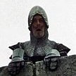
Procopius Posted September 6, 2018 Share Posted September 6, 2018 And here's a replica of the bracket itself: 5 1 Link to comment Share on other sites More sharing options...
Biggles87 Posted September 6, 2018 Share Posted September 6, 2018 Well done to PC. I've been looking through my references and also found the top photo but the second one is invaluable. It looks like the arm on the gunsight is just a convenient way for the kit producers to attach it, and perhaps it was not connected to the IP at all. We live and learn. John 2 Link to comment Share on other sites More sharing options...
keefr22 Posted September 6, 2018 Share Posted September 6, 2018 18 hours ago, Navy Bird said: I thought about the wine foil, but that would mean I would have to run out and get a bottle. Which in turn means I would drink it, and you don't want to see what I come up with for inebriated Sutton harnesses. I'm lucky as I don't much care for wine tbh but have a friend who does & he's given me a lifetime's supply of foil...! Keith 1 1 Link to comment Share on other sites More sharing options...
giemme Posted September 6, 2018 Share Posted September 6, 2018 2 minutes ago, keefr22 said: I'm lucky as I don't much care for wine tbh but have a friend who does & he's given me a lifetime's supply of foil...! Keith I'm lucky as I quite care for good wine, so I have a lifetime supply of foil... Sorry for the OT, Bill - although wine foil was mentioned to reproduce scale harness, right? Ciao 1 2 Link to comment Share on other sites More sharing options...
giemme Posted September 6, 2018 Share Posted September 6, 2018 (edited) 44 minutes ago, Biggles87 said: Well done to PC. I've been looking through my references and also found the top photo but the second one is invaluable. It looks like the arm on the gunsight is just a convenient way for the kit producers to attach it, and perhaps it was not connected to the IP at all. We live and learn. John From PC's pic it looks as though the IP has slots to avoid interfering with the gunsight mounting frame. Excellent pics, PC. Thanks for posting them! Ciao Edited September 6, 2018 by giemme 1 Link to comment Share on other sites More sharing options...
bigbadbadge Posted September 6, 2018 Share Posted September 6, 2018 Great work on the interior Bill starting to really come together now. Thank you to Procopius for posting the images above too. It will really help with my Vb. Keep up the good work All the best Chris 1 Link to comment Share on other sites More sharing options...
Biggles87 Posted September 6, 2018 Share Posted September 6, 2018 The circular silver/grey object on the port upper sidewall looks like the camera indicator, thar's certainly where it was on the Mk V. The ' dimmer ' is associates with the later gyro gunsight as far as I know. All this discussion and watching Chris' 1/32 Mk V build is making me want to restart my HobbyBoss Mk V trop. John 2 1 Link to comment Share on other sites More sharing options...
Navy Bird Posted September 6, 2018 Author Share Posted September 6, 2018 Thanks everyone. Now I have a good understanding about the gunsight mounting, and I think I can fake replicate it. The resin bracket from Barracuda isn't exactly like the photo, but I think it's close enough. I think the gunsight can be added once the fuselage halves are together, and then I can mount the resin bracket to it and the two fuselage sides. This will be better than mounting it to the windscreen as Barracuda suggest (I think). And I may not have to attach the gunsight as Tamiya intended (through the slot in the instrument panel). We'll see. In the first picture posted by @Procopius, does it look to you guys like there is a glass plate mounted behind the gunsight? I don't mean the one on top of the gunsight, that's different. Tamiya moulded their gunsight in clear plastic, and has a rather wide flat plate in this area. I wonder if that is what they were trying to reproduce. Man, I learn something about Spitfires every day. And that's a good thing! Cheers, Bill PS. Heading to Maryland tomorrow for a nice four day visit with my son and two lovely granddaughters. I'll be mostly off-line until I get back, Loretta. 3 Link to comment Share on other sites More sharing options...
Christer A Posted September 7, 2018 Share Posted September 7, 2018 The difference in gunsight mounting might be due to the differences in guns sight used? I'm just guessing here but the gunsight in VIII is probably a bit more advanced than in a Vb that would require a different mounting bracket. Link to comment Share on other sites More sharing options...
giemme Posted September 7, 2018 Share Posted September 7, 2018 (edited) 13 hours ago, Navy Bird said: In the first picture posted by @Procopius, does it look to you guys like there is a glass plate mounted behind the gunsight? I don't mean the one on top of the gunsight, that's different. Tamiya moulded their gunsight in clear plastic, and has a rather wide flat plate in this area. I wonder if that is what they were trying to reproduce. Not sure what you mean, Bill (or I can't see it at all): I tried to zoom in that pic and all I see, apart from the reflector glass, is the "double" glass on the windshield - more properly the armored glass, is it? 😕 Ciao Edited September 7, 2018 by giemme 1 Link to comment Share on other sites More sharing options...
Navy Bird Posted September 15, 2018 Author Share Posted September 15, 2018 Hey, remember me? Still alive and well, and thinking I've done just about all I can with the cockpit. I decided to use the instrument panel from Yahu, and I applied it over the top of the misprinted Eduard panel (after I sanded it flat). The control column was then added, And I took some photos of how the sidewalls look prior to buttoning up the fuselage. The port side: And the port side temporarily added to the fuselage half (I added the gun camera indicator and some stickers on the air cylinders): The starboard side: And with the fuselage: As I start closing up the fuselage, I'll be adding the pilot's oxygen hose to the starboard side. It's not shown in these photos but it's ready to go. As far as I can tell, there is no need to add the cables that lead from the rudder pedals to the rear of the aircraft, as they won't be seen when you look into the open cockpit. Here's a better look at the IP: I'm sure that someone will notice that the flaps control is in the "down" position. On the ground with no pilot and the engine not running! I'll never hear the end of it. And how things look from above with both sidewalls fitted: The gunsight will be added later, and I'll be attempting to build a mount like the real thing and not just stick it into the slot in the instrument panel. I did a test fit of the cockpit sub-assembly into the fuselage, and it seems to fit just fine. I'm sure there will be a gotcha somewhere. I'll mark up the earlier gunsight photo to show what I meant about a possible second piece of glass. It may not be there, I'm probably just off my rocker again. Cheers, Bill PS. Just realised that the Tamiya kit does not include a headrest. Hmm... 18 Link to comment Share on other sites More sharing options...
Stew Dapple Posted September 15, 2018 Share Posted September 15, 2018 Lovely job on the cockpit Bill, looks very convincing to me Strange Tamiya missed the headrest though, it is quite a prominent feature... Cheers, Stew 1 Link to comment Share on other sites More sharing options...
Biggles87 Posted September 15, 2018 Share Posted September 15, 2018 (edited) 2 hours ago, Stew Dapple said: Lovely job on the cockpit Bill, looks very convincing to me Same here. Perhaps Tamiya looked at a restored Warbird when they were researching the cockpit, not all of them have the headrest fitted When I first saw MH434 in the late'70s the headrest wasn't fitted. John Edited September 15, 2018 by Biggles87 1 Link to comment Share on other sites More sharing options...
CedB Posted September 15, 2018 Share Posted September 15, 2018 Beautiful work Bill, very realistic. Good choice on the i/p too 1 Link to comment Share on other sites More sharing options...
Max Headroom Posted September 15, 2018 Share Posted September 15, 2018 Re the headrest, I thought that the Mk.IX omitted it? As far as I know only those Vc’s converted to IX’s definitely had them. Trevor 1 Link to comment Share on other sites More sharing options...
Hamden Posted September 15, 2018 Share Posted September 15, 2018 That is a stunning cockpit Bill - a stand alone model in its own right! Roger 2 Link to comment Share on other sites More sharing options...
giemme Posted September 15, 2018 Share Posted September 15, 2018 31 minutes ago, Hamden said: That is a stunning cockpit Bill - a stand alone model in its own right! Roger Agreed 100%! And the weathering looks spot on too Ciao 1 Link to comment Share on other sites More sharing options...
Badder Posted September 15, 2018 Share Posted September 15, 2018 Hi Bill, I've never built an aircraft kit, but this particular kit is one of the very few that I am sorely tempted to try. However, threads like this are huge discouragement. There's no way I could match this kind of precision, quality and artistry, EVER. Sublime work in all respects. I think I'll stick to armour and the many advantages of mud. Rearguards, Badder. Link to comment Share on other sites More sharing options...

Recommended Posts
Create an account or sign in to comment
You need to be a member in order to leave a comment
Create an account
Sign up for a new account in our community. It's easy!
Register a new accountSign in
Already have an account? Sign in here.
Sign In Now