hendie Posted March 1, 2017 Share Posted March 1, 2017 10 hours ago, Reconcilor said: OK - it's all Hendie's fault Thanks ! It always gives me a great sense of pride when I get the blame for other folks good work 16 minutes ago, Reconcilor said: What could be better than this?Well your Pullman build for one thing! nah.... not better... just different, that's all. 2 Link to comment Share on other sites More sharing options...
Bandsaw Steve Posted March 7, 2017 Author Share Posted March 7, 2017 Details and Gross Stupidity I have decided to start putting headings on each of my major postings. This one was going to be called 'Details...Details' until about 5 minutes ago when I realised what a complete dullard I have been over the last few days. As posted before I have been really looking forward to getting some primer on this model but before I can do so there are a handful of potentially tricky details to get in position. The first were two quite small but distinctive trailing edge 'stakes? 'fairings? 'fillets?' at the trailing edge of the wing root. You can see them here fitted. It's not a very interesting story really - these have just been shaped from bass-wood and PVA glued in place - since this photo they have been filled with Vallejo filler and sanded to shape and they look OK now. Here's a blurry photo of them getting sanded. Suffice to say they came up alright and didn't cause any grief. It was the next part of the story that causes grief. As you can see from this drawing there is a prominent bullet-shaped fairing at the rear of the tailplanes that houses an anti-collision light. I was thinking of leaving this off - because it is generally not very visible in photos - most of which are taken from the side and the bullet shaped extension is often / usually obscured by the tailplanes. But since I was working to these drawings I felt it had to go on - even though it was in a difficult spot and looked like it was going to be difficult to 'engineer'. I also however, noted two small reinforcing fillets under the tailplanes that blended into the 'bullet' so I figured that this was the key to a successful structural approach to creating the cursed thing. I figured that if I could carve a split into a fine length of dowel then either side of the split could be glued under the tailplanes (into the positions of the fillet) and that there would be sufficient surplus dowel left for me to carve the bullet from. This bullet would then stick out of the aircraft like it's supposed to. So far so good...but you know what's going to happen of course... Yep! Inevitable really. So then I thought I would try again - with plastic. Same approach... Yep - you guessed it. So then I had a think and dreamed up a new approach. Drill a hole in the necessary spot, Fit a length of carbon fibre - amazingly tough stuff this - will bend in long lengths and can be cut easily but will not break. I was starting to think I was clever. Has anyone spotted the fatal flaw in all of this yet? Now I did a naughty, naughty thing! As I do not own a lathe I used a power-drill as an improvised lathe. I chucked a piece of dowel into the drill bit and shaped the bullet point using sandpaper. A golden rule of industrial safety is to never improvise tools - but I got away with it in this instance. One day I might buy a very small lathe. So now all I needed to do was drill a hole in the bullet and fit it onto the carbon fibre. Perfect - and after a bit of filler and sanding I was feeling well happy with myself. I had overcome a technical challenge, used a new material (carbon fibre) that I reckon I will use over and over again in future and had made a passably accurate anti-collision light fairing for my Mig. Result! Or so I thought... Just now when I started writing this up I had another look at this image and the pure unadulterated stupidity of what I had done finally hit home. The 'large bullet shaped fairing' that you can see isn't a 'large bullet shaped fairing at all!' It's the tip of the tail fin! The real anti-collision light fairing is much smaller and is not really represented in this view at all. The damned thing is tiny! About 10% of the size of the mammoth overgrown knob that I've stuck on the back of my poor embarrassed Mig. The poor aeroplane now has to fly around the countryside with a 'growth' sticking out of it's... OK...this has to be corrected. But primer first - I can wait no longer... 9 Link to comment Share on other sites More sharing options...
Vanroon Posted March 7, 2017 Share Posted March 7, 2017 Oo, primer, progress. Missed your company and banter on Saturday. Grant 1 Link to comment Share on other sites More sharing options...
Bandsaw Steve Posted March 7, 2017 Author Share Posted March 7, 2017 (edited) Thanks mate! A family event cropped up at the last minute and it was kinda compulsory. It was actually pretty good too! See you next time, and next time I might just have a canopy mold for your vac-forming pleasure. Edited March 7, 2017 by Reconcilor Link to comment Share on other sites More sharing options...
Vanroon Posted March 7, 2017 Share Posted March 7, 2017 A canopy buck. Must get some testing of new machine done on old bucks found in the recent move. Grant 1 Link to comment Share on other sites More sharing options...
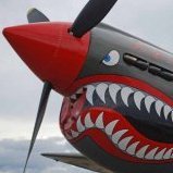
Bandsaw Steve Posted March 8, 2017 Author Share Posted March 8, 2017 Finally, Primer! OK it's time - this thing's going to get painted. Overall I'm fairly happy with the project but right now it looks 'bitsy' and 'messy'. A good even coat of primer will, I hope, make this look a lot more respectable. First step is to make sure all the last details are on - there's a very prominent reinforcing sheet added to the tail where the tailplanes meet the tailfin and that's been modelled with very, very thin (0.13mm in fact!) Evergreen plastic card. I have also secured the wing fences in their slots using cyanoacrylate superglue. Now I'm all ready to start masking. For the primer coat we need very little masking - just some tape inside the cockpit and then any last gaps filled with silli-putty. There's also a dab of Windsor and Newton masking fluid on the front of the cine camera lens. I have a 25cm long length of plastic tubing that fits exactly into the jet outlet so that makes an ideal painting handle. OK - let's go to the shed and spray some paint! I have a can this stuff waiting for use. I have tested it on plywood - and it works very well, so I'm not going to bother with any wood-primer on the tailplanes. And now the big moment - the first primer hits the model! After leaving the first coat an hour or so to dry and harden a bit I gave it a second coat. And here's the result - one grey 1/48 Mig15. Much tidier looking than it was! Shame it's not a modern jet in low-vis colours; I could walk away and call it finished right now! I am happy with this. It almost has a 'shark-like' quality in this view. So that's the long-awaited primer on. As you can see there's some tidying up to do; some rough surfaces to fix and so-forth but I am pleased with the outcome. I hope you like it too! Next step - Start on the Natural Metal Finish. I have a strong suspicion that it's going to be all downhill from here! 10 Link to comment Share on other sites More sharing options...
hendie Posted March 8, 2017 Share Posted March 8, 2017 it's always a good feeling when the first coat of primer goes on isn't it ? Looks good though I fear that with a natural metal finish, you're going to be micromeshing for some time to come 1 Link to comment Share on other sites More sharing options...
AdrianMF Posted March 8, 2017 Share Posted March 8, 2017 That looks very sharp! You wouldn't believe it was a "wooden wonder". Regards, Adrian Link to comment Share on other sites More sharing options...
John_W Posted March 8, 2017 Share Posted March 8, 2017 Amazing as always. 1 Link to comment Share on other sites More sharing options...
Bandsaw Steve Posted March 12, 2017 Author Share Posted March 12, 2017 (edited) Inspect, Fill, Sand, Inspect, Fill, Sand... I think Hendie got it right with 'I fear that with a natural metal finish, you're going to be micro-meshing for some time to come...' Yep! However, in addition there are one or two corrections to make before attempting the finishing coats. Here's the first one; in the photo below you can see a prominent 'notch' running around the fuselage about 2 scale metres ahead of the cockpit opening. This is the left-over scar from where I inserted a thin slice of plywood to fill the kerf from the rebate cut ('Kerf' is a real word I only recently learned - google it if you like - it means the slot or incision left by a saw). The Photo below is a reminder from what seems like a long, long time ago. That layer of plywood ahead of the cockpit is what's causing the issue. It would seem that during subsequent sanding and shaping it has 'eroded' more than the surrounding, hard Jarrah. Under a layer of primer the error stands out hideously - under Natural Metal it will look even worse. It should be fairly simple to fix I hope. Just scour the area that needs filling (in this case with a series of X shaped scalpel cuts) and fill with Vallejo filler. And the other job that needs to be done is to trim that tail fairing down to a sensible size. Mercifully, this turned out to be a fairly simple exercise in whittling and sanding. And with these two jobs done and some other patching (mostly with very quick drying 'Perfect Plastic Putty') my Mig 15 looked like this. Ready for... Sanding, sanding, sanding...you know the drill. I normally find sanding 'therapeutic' - but not at this stage. Here I have to concentrate because one slip and some detail or another will be damaged. OK - she's ready for her second primer. This second Primer is a lighter dusting than the first one. A bit more sanding with increasingly fine grades of micromesh (down to and including 12000) and I think we are ready to try spraying the first layer of metallic aluminium. I'm hoping that it will go on tomorrow night, so stay tuned. I have selected and tested the paints on a block of Jarrah. I think I'm ready to go... Edited March 12, 2017 by Reconcilor 5 Link to comment Share on other sites More sharing options...
hendie Posted March 12, 2017 Share Posted March 12, 2017 painting always fills me with 50% anticipation and 50% fear. (and that's just bog standard colors) I think I'd need a good stiff drink attacking this one Link to comment Share on other sites More sharing options...
Bandsaw Steve Posted March 12, 2017 Author Share Posted March 12, 2017 Good idea! Make mine a Glenffidich please. 1 Link to comment Share on other sites More sharing options...
Jaffajake Posted March 13, 2017 Share Posted March 13, 2017 Looking good with the primer coat on. Should look even better with the NMF! 1 Link to comment Share on other sites More sharing options...
Bandsaw Steve Posted March 13, 2017 Author Share Posted March 13, 2017 NMF - Part 1 Well here goes! For the viewing pleasure of 'Wyvern S4' 'Van Roon' 'The Baron' 'Chaotic Mike' and 'Mike Romeo' all of whom voted for an attempt at a Natural Metal Finish...here comes the first coat! Remember, if this doesn't work - I'm reverting to a Korean War stripy camouflage scheme. Generally I use an airbrush. But on this occasion I think that it'll be quicker and easier and more consistent to use a metallic lacquer spray can. Here's the chosen weapon'. If you look carefully in the background you can see the intended victim shivering in fear. The moment before the very first lick of NMF hits the target. And the result a few minutes latter - paint still drying of course. Not perfect by any means - but as my father would say...'a blind man would be pleased to see it' or alternatively... 'It'll pass in the rush with the lights out'... Suffice to say - it could be worse. Just view these photos on a screen no bigger than an I-phone 6's and it should look OK. Next step? Inspect, sand, fill...Inspect, sand fill (or maybe just inspect and sand?). 8 Link to comment Share on other sites More sharing options...
hendie Posted March 13, 2017 Share Posted March 13, 2017 Well, I have to admit that on a first pass, that's turned out a lot better than I expected. That is meant in no way to denigrate your skills whatsoever - it's more that I anticipated the shiny finish to show up a lot more flaws opportunities for improvement It is certainly looking good. Great job ! 1 Link to comment Share on other sites More sharing options...
Jaffajake Posted March 13, 2017 Share Posted March 13, 2017 2nded 1 Link to comment Share on other sites More sharing options...
Gary West Posted March 13, 2017 Share Posted March 13, 2017 You have so nailed that! 1 Link to comment Share on other sites More sharing options...
Churchill Posted March 13, 2017 Share Posted March 13, 2017 22 hours ago, Reconcilor said: Good idea! Make mine a Glenffidich please. Pub malt. Try a Glenlivet, 16 yr old. I'd join you, but I've been off the sauce since June. 1 Link to comment Share on other sites More sharing options...
Vanroon Posted March 16, 2017 Share Posted March 16, 2017 That came out all right Reconciler. . Buffable metallic paint can improve with polishing and other handling but is fairly fragile when handled repeatedly before being sealed. Testors metalizer sealer is very good. G 1 Link to comment Share on other sites More sharing options...
Bandsaw Steve Posted March 16, 2017 Author Share Posted March 16, 2017 Ok. Sounds like good advice! Does the sealant go on before or after the decals? The best way to apply decals for an NMF is causing me some concern - normally, on a painted finish, I would paint , apply a gloss finish (say pledge), apply decals, seal with more pledge and then spray on the final satin or Matt varnish. But I'm unsure if that approach is compatible with this finish. Any thoughts welcome. Am working on that canopy 'buck' tonight. Link to comment Share on other sites More sharing options...
Vanroon Posted March 16, 2017 Share Posted March 16, 2017 Carving a buck, not a stag. Ive sprayed one coat of TMS (testors metalizer sealer) before the decals and once or twice again after to merge them in. However, the more clear, the more toy like. Are your decals glossy?, perhaps give them a coat before application. G 1 Link to comment Share on other sites More sharing options...
Bandsaw Steve Posted March 19, 2017 Author Share Posted March 19, 2017 Canopy - Part 1 When I were a lad I, used to make my canopies by heating a small sheet of clear plastic with a candle and then 'smash molding' them over a carved wooden former. Ah... those were days! But now it's the 21st century and my mate down the road, Mr 'Van Roon' owns a vac-forming machine. Now, I've never vac-formed anything in my life and to be honest I'm still a bit hazy on the subject, but I've just been dying to have a crack at it. So let's have a go at vac-forming the canopy for this project. First however, I am going to ramble on again, about some wood. This is a piece of 'liquidambar' (no spelling mistake it's ambar with an 'ar' not 'amber with an er'). Apparently it's also known as 'American Sweetgum' and 'Satin-Walnut'. This piece of wood was sold to me by a vendor who highly recommended it for carving and whittling, and wow! - did that guy know what he was on about! This stuff is incredibly good to work with in every regard and, if ever I'm stupid enough to embark on a project like this again, this is what my next fuselage will be made from. Shown below is a the result of a simple test to see what it might be like to scribe panel lines on this stuff - the result is sensational - each line is straight and clean and even. This is much better than I could manage with Jarrah. So - Liquidambar it is for the rest of the canopy making project. In order to make a vac-form anything it seems you need a mold (also known as a 'form' or a 'buck') to shape the plastic. I believe that the mold can either be 'male' or 'female' and it seems that people that really know what they are doing recommend 'female' or 'concave' molds. Such molds however are harder to make so I'm going to go the easy way and carve out a 'male'. For those of you who have been following along the next few steps should seem quite familiar... Stick on a profile view of the required shape. Remove most of the unwanted material with a saw, in this case a fret saw. Cut in closer to the final profile with a chisel, here a scoop chisel. Use sandpaper to achieve a more accurate final profile. Now repeat the process on the top view. As you can see - because the plan view now needs to be applied to a curved surface the length of the original drawing is not long enough. This is a classic case of a 'foreshortening problem' for which there are doubtlessly many highly sophisticated mathematical solutions. Here's my fix! Cut the paper up and move the bits about until the framework lines up. This is close enough for jazz music. Cut with a rusty razor saw whose handle fell off years ago. It actually is rusty and will be thrown away soon - but after waxing the blade with candle wax it still cut remarkably well. Please take better care of your tools than I do. Rough cut complete. Chisel the vertical shape. (I have taken much better care of my chisels than that poor razor saw). Sand to shape. Chisel and sand, being careful to leave the red marker stripe... Getting there - more sanding required at this point. Note how the armoured windshield is red - that's because I had already achieved the necessary flat panel on this surface and wanted it to survive the sanding / chiseling attack. If the red remains, the shape is intact. And after some final fine sanding and polishing I can cut the canopy mold off it's base. Leaving this encouraging looking shape. That's enough for now - but suffice to say, the mold is not actually complete. There's plenty more work to follow. Best Regards, Reconcilor 6 Link to comment Share on other sites More sharing options...
MikeR Posted March 19, 2017 Share Posted March 19, 2017 That's coming along very nicely indeed! Mike. 1 Link to comment Share on other sites More sharing options...
John_W Posted March 19, 2017 Share Posted March 19, 2017 Beatiful finish on the wood. Lovely close grain. Did you use sealer, or is that bare wood? 1 Link to comment Share on other sites More sharing options...
Vanroon Posted March 19, 2017 Share Posted March 19, 2017 No scraps of that left in the shed. I checked. Now for a close-up. http://2.bp.blogspot.com/-MkHfCGaa2ZI/Tk9xalbwGMI/AAAAAAAABcU/IKUiJ767dkg/s1600/mig-15_02_of_17.jpg Note the lip around the cockpit. G 1 Link to comment Share on other sites More sharing options...

Recommended Posts
Create an account or sign in to comment
You need to be a member in order to leave a comment
Create an account
Sign up for a new account in our community. It's easy!
Register a new accountSign in
Already have an account? Sign in here.
Sign In Now