Gary West Posted December 8, 2015 Share Posted December 8, 2015 Such an entertaining build :-) Link to comment Share on other sites More sharing options...
Devcon 1 Posted December 10, 2015 Author Share Posted December 10, 2015 It's coming together but I need to decide whether to try a scratch built engine to fill the void behind the cover, there doesn't seem to be a great deal of distance in there between the inlet and exhaust which looks to me like the engine would be very short in length, I'll need to try and find some photos to see what goes on under there. Any pointers gratefully received. The inlet starts roughly where the front of that box is at the top of the void. Kind Regards John 1 Link to comment Share on other sites More sharing options...
Devcon 1 Posted December 13, 2015 Author Share Posted December 13, 2015 Progress delayed by the application of the PE parts and the completion of a Lancaster BII together with some 1/72 stablemates, all destined for my shed roof diorama......## Regards John 3 Link to comment Share on other sites More sharing options...
Martian Posted December 13, 2015 Share Posted December 13, 2015 As this is a cutaway model, I think I would be tempted to add an engine, its the sort of thing you would expect to see were this a cutaway drawing, which is what I understand you as being trying to replicate in three dimensions instead of two? Martin Link to comment Share on other sites More sharing options...
paul_c Posted December 13, 2015 Share Posted December 13, 2015 (edited) Brilliant work, I'm loving this. Regarding the engine, the RTM322 is surprisingly compact and a replica would look great up in that empty bay Edited December 14, 2015 by paul_c 1 Link to comment Share on other sites More sharing options...
Devcon 1 Posted December 13, 2015 Author Share Posted December 13, 2015 That's decided then, I'll have a go at an engine. Many thanks for the pic Paul, it does look very compact. Never had a go at proper scratch building so we'll see how it goes. Regards John 1 Link to comment Share on other sites More sharing options...
Martian Posted December 14, 2015 Share Posted December 14, 2015 That's decided then, I'll have a go at an engine. Many thanks for the pic Paul, it does look very compact. Never had a go at proper scratch building so we'll see how it goes. Regards John Judging by what you have achieved thus far, you will be fine. Martin Link to comment Share on other sites More sharing options...
paul_c Posted December 14, 2015 Share Posted December 14, 2015 I'm sure you be fine John. Remember to do the floor and firewall as well. They are both titanium and covered in various runs of fire wire. The intake stays in place when the engine door is open so you don't have to worry too much about the front end. If you need any pointers, give me a shout. I worked on Merlin depth maintenance for 6 years when I was in the RAF........ Link to comment Share on other sites More sharing options...
Devcon 1 Posted December 14, 2015 Author Share Posted December 14, 2015 Well here's the first attempt. I'm glad some kit makers add detail to a model even though it can't be seen. I've cut out from the inlet what looks like the first intake part of the motor which when added to some plastic tube will form the basis for the engine. It looks better in the flesh. I've got to slim down the outer ducting a bit which is from some pared down sprue but I think I've got a basis for a reasonable representation of a motor. Some filling to do then add some of the components that surround the casing. Hi paul_c. they must have been fascinating machines to work on, I think I can picture the bulkhead/floor but will need to make it removable so I can change the lighting battery. I understand what you mean about the inlet shroud but I'm going to have to make this removable, again to access the battery. Regards John 1 Link to comment Share on other sites More sharing options...
Martian Posted December 15, 2015 Share Posted December 15, 2015 Looks like you have the basis of a decent looking engine there. Martin Link to comment Share on other sites More sharing options...
shark 64 Posted December 15, 2015 Share Posted December 15, 2015 Looking good my friend. I am also doing a folded tail...but in a bigger size and different aircraft. Will be watching your build. Oliver Link to comment Share on other sites More sharing options...
Devcon 1 Posted December 15, 2015 Author Share Posted December 15, 2015 Thanks Martin, I'm happy so far. Thanks Oliver, I've been watching your Seahawk build in awe and bought the mag with your Huey build in.I just don't know how you achieve the "accurately engineered" look to the scratch built stuff let alone the painting standard. Kind Regards John Link to comment Share on other sites More sharing options...
paul_c Posted December 15, 2015 Share Posted December 15, 2015 (edited) That's looking like a decent basis for the engine John. The bulkhead and floor should be easy to reproduce as they have no real shape to then. You could even have the engine/floor/bulkhead as a single, removable assembly. Edited December 16, 2015 by Mike Removing large photo-quote 1 Link to comment Share on other sites More sharing options...
RMCS Posted December 15, 2015 Share Posted December 15, 2015 Excellent subject..great build so far... Link to comment Share on other sites More sharing options...
Jackster Posted December 15, 2015 Share Posted December 15, 2015 Really enjoying this build :-) Link to comment Share on other sites More sharing options...
Leonl Posted December 16, 2015 Share Posted December 16, 2015 Brilliant work on the engine.... It'll be a stunner! Link to comment Share on other sites More sharing options...
Truro Model Builder Posted December 16, 2015 Share Posted December 16, 2015 I've just come across this build. Superb work so far. Link to comment Share on other sites More sharing options...
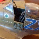
Devcon 1 Posted December 17, 2015 Author Share Posted December 17, 2015 Thanks for all your interest and comments. First finished engine is a disaster, in a rush I added too much San Miguel before spraying with some aluminium auto paint, it reacted with the primer which had only just been sprayed. In the photo it looks horrible although prior to spraying I was very pleased with the result. It looks not so bad in the flesh so will leave it for the moment and correct it on my second build, what I will do though is make the engine and bay setup prior to fitting the roof now I can see what space I have to work with. The exposed parts of the tailboom are nearly done. The camera doesn't miss much, this looks a bit rough close so will try and tidy it up a bit. The eagle eyed out there will notice I got the angle of the side strakes wrong and should I think be angled up a bit more. I've wondered what these strakes do aerodynamically so if anybody out there knows. Regards John 3 Link to comment Share on other sites More sharing options...
Martian Posted December 17, 2015 Share Posted December 17, 2015 I agree you need to have another bash at the engine if you want it to be to the same standard as the rest of the build, the tail fold does look good though. Martin Link to comment Share on other sites More sharing options...
Devcon 1 Posted December 20, 2015 Author Share Posted December 20, 2015 Had a go at the quads to see how they'll look.. The main build is all phototeched and ready for masking and priming, I'll build up the courage to have a go in the next few days... Regards John 5 Link to comment Share on other sites More sharing options...
Benbow Posted December 20, 2015 Share Posted December 20, 2015 I've wondered what these strakes do aerodynamically so if anybody out there knows. Regards John The "strakes" are pretty much similar to a wing as in they create a pressure differential either side of the tail boom. As more power is "pulled" in there is a greater downdraft from the main rotor. This torque has to be countered by the tail rotor which too is demanding power from the engines. With the strakes providing an aerodynamic effect this reduces the amount of power required for the tail rotor and thereby increases efficiency, fuel consumption and allows for greater lift - well that's the theory sort of.... Hope this helps. Benbow http://blog.aopa.org/helicopter/?p=309 1 Link to comment Share on other sites More sharing options...
Martian Posted December 21, 2015 Share Posted December 21, 2015 The Quads look great! I must say that I am amazed at how quickly you are getting through this build, it would take me many months to get this far. Martin Link to comment Share on other sites More sharing options...
Devcon 1 Posted December 24, 2015 Author Share Posted December 24, 2015 Thanks for the info on strakes Benbow . Relatives have stopped play for a few days so frustratingly no progress. But I did notice Airfix are selling the Merlin again for £19.99 together with some other deals. Regards John Link to comment Share on other sites More sharing options...
Devcon 1 Posted December 30, 2015 Author Share Posted December 30, 2015 Back on it now so here's progress to date... Filled up landing gear bay with a bit of imagination. I've glued the top, side and chaff dispenser (I think) together to make one assembly. First go at the folding head, as I mentioned earlier this is a bit of a test build to learn from. I wish some clever manufacturer out there would make a folding upgrade kit... Last bit of glazing in place. Masking has been tedious so tried a bit of Depron foam wedged in the hole. The load hook bay makes a handy hole for the painting rod. Regards John 3 Link to comment Share on other sites More sharing options...
Nigel Heath Posted December 31, 2015 Share Posted December 31, 2015 Looking good. Link to comment Share on other sites More sharing options...

Recommended Posts
Create an account or sign in to comment
You need to be a member in order to leave a comment
Create an account
Sign up for a new account in our community. It's easy!
Register a new accountSign in
Already have an account? Sign in here.
Sign In Now