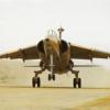
horrido109 Posted December 11, 2013 Share Posted December 11, 2013 Hi everybody,This is my first "in progress" post. I am by no means a professional builder and the purpose of my post is purely for interest to those wanting to see how the new Kittyhawk Mirage F1 single seater goes together. Photography is also not my strong point so please forgive the quality of my (Cellphone taken) pictures. This is the kit:My attempt will be to turn it into this:This is the South African Air Force example of the Mirage F1C, called the CZ in SA. This aircraft was the first example painted in the blue/grey air superiority scheme. Shortly after it was painted in this scheme this aircraft shot down an Angolan Mig-21MF with its 30mm canon. Soon all F1CZs were painted in this scheme.The initial impression of the kit is very good. Mould quality is excellent and the kit has a lot of detail. Certainly an improvement over the Esci/Italeri example. The kit is however not without faults of it's own. the main problem for me being the shape of the intakes. More on it here: http://www.britmodeller.com/forums/index.php?/topic/234948924-kittyhawk-mirage-f1-intake/I decided to use the Pavla intakes. Although originally designed for the Esci/Italeri kit, it can be made to fit this kit. Some sanding is required but the general result is acceptable. I also used some plastic card to build up the area where the intakes join the fuselage to get a better fit as the Kittyhawk kit is slightly deeper in this area:I'll post more pictures shortlyVictor 1 Link to comment Share on other sites More sharing options...
horrido109 Posted December 11, 2013 Author Share Posted December 11, 2013 (edited) One item neglected by the Esci kit was the interception light on the outer port intake. The Kittyhawk kit does offer a small clear insert here but I decided to scratch build this light and its housing to get a more realistic result. Once masked and painted it should look the part: I also started dry fitting the Pavla cockpit set at this point. I was pleasantly surprised by the little effort required to fit this set to this kit. I had to remove the nose gear bay detail moulded onto the bottom of the cockpit floor though. The kit part will be used here only augmented with some wiring and plumbing.Another problem with this kit is the shape of the nose cone. It is too droopy and curved at the top. With careful sanding and a little patients I was able to get an acceptable result. Some re-scribing and finishing still required:RegardsVictor Edited December 11, 2013 by horrido109 1 Link to comment Share on other sites More sharing options...
horrido109 Posted December 11, 2013 Author Share Posted December 11, 2013 One of the things that makes the Kittyhawk kit stand out compared to the Esci kit is the fact that it can be built with a dirty wing (ie.Slats and flaps deployed). Unfortunately Kittyhawk provides separate slats but not separate inboard leading edge flaps. These are moulded up. On the real aircraft the inboard leading edge flaps are always lowered when the slats and trailing edge flaps are deployed. I found it an easy task to lower the kit flaps. I simple made a cut with a thin Tamiya blade where the flaps joins the slats:I then used a scriber to remove some plastic at the root of the flap. I made quite a deep groove but did not go all the way through:After this simple procedure it was only a matter of gently bending the flap down until it reached the correct angle. I then simply ran some Tamiya extra thin cement into the groove and the flap was done. I am very satisfied with the result:Thanks for lookingVictor 3 Link to comment Share on other sites More sharing options...
sharkmouth Posted December 11, 2013 Share Posted December 11, 2013 Thank you for this as I have the kit (hey, it has a sharkmouth) to build after the MiG-25. Regards, 1 Link to comment Share on other sites More sharing options...
guillaume320 Posted December 12, 2013 Share Posted December 12, 2013 An excellent start I have to say! I have a question with regards to the Pavla cockpit: Is the gear bay molded on the underside? And if so, how does it match with the opening on the fuselage halves? With regards to the leading edge flaps, I think you should have cut them further outboard. What I mean is I think when all hi-lift devices are retracted, part of the outboard slat overlaps the inboard flap... I will try to post some pictures to show what I mean. But your sollutions is already 100 times better than what's given in the box!!! I'm looking forward to an update!! Best regards, Guillaume Link to comment Share on other sites More sharing options...
guillaume320 Posted December 12, 2013 Share Posted December 12, 2013 (edited) I hope the following pictures make sense... The plastic strip is to later get rid of the 'step' which is non existant when the slat deploys... I had to trim it back later as it had too much chord. On the next picture, you see a dryfit of what I've done so far. You also see I'm in the process of 'building up' the area where the slat overlaps the flap... And also a comparaison with what you get OOB.... Edited December 12, 2013 by guillaume320 2 Link to comment Share on other sites More sharing options...
mmaker Posted December 12, 2013 Share Posted December 12, 2013 Thats a great start! Please Kittyhawk make it 1/72 too... Link to comment Share on other sites More sharing options...
guillaume320 Posted December 12, 2013 Share Posted December 12, 2013 Excellent job on the nose correction as well... I'm gonna try it on my next. Good alternative to robbing an Italeri nose! Link to comment Share on other sites More sharing options...
MIRAGEF1 Posted December 12, 2013 Share Posted December 12, 2013 (edited) Flipping brilliant....I am a fan.... Edited December 13, 2013 by MIRAGEF1 Link to comment Share on other sites More sharing options...
horrido109 Posted December 12, 2013 Author Share Posted December 12, 2013 I have a question with regards to the Pavla cockpit: Is the gear bay molded on the underside? And if so, how does it match with the opening on the fuselage halves? The Pavla set fits surprisingly well. However, the nose gear bay detail needs to be removed as it does not align with the kittyhawk kit at all. I separated the resin cockpit part from the resin wheel bay and will be using the kit wheel bay: 1 Link to comment Share on other sites More sharing options...
horrido109 Posted December 12, 2013 Author Share Posted December 12, 2013 With regards to the leading edge flaps, I think you should have cut them further outboard. What I mean is I think when all hi-lift devices are retracted, part of the outboard slat overlaps the inboard flap... Guillaume you are absolutely right. I was still getting to that part on my build. You and I think the same way because I used the exact same procedure to correct the flaps. I finished the one wing already but still waiting for some Mr Surfacer to dry. I should be able to post pictures tomorrow of the completed wing then you will be able to see where the slats on mine overlaps the flaps. The dimensions of the inboard leading edge flap on the real aircraft is 1820mm, which translates to 38mm in 1/48 scale. The kit inboard leading edge flap is only 34mm which translates exactly to the 1650mm visible on the real thing once retracted as 170mm is hiden below the slat: I will post some pictures of my effort to have this fixed tomorrow. Regards Victor PS: Please forgive the quality of the pictures. 1 Link to comment Share on other sites More sharing options...
Seversky Posted December 13, 2013 Share Posted December 13, 2013 Very good! I did the same thing differently. http://scalemodels.ru/modules/forum/viewtopic.php?t=45844&start=80 Link to comment Share on other sites More sharing options...
exdraken Posted December 13, 2013 Share Posted December 13, 2013 Thanks for your work in progress, interesting work on h intakes and interception light! This is the South African Air Force example of the Mirage F1C, called the CZ in SA. This aircraft was the first example painted in the blue/grey air superiority scheme. Shortly after it was painted in this scheme this aircraft shot down an Angolan Mig-21MF with its 30mm canon. Soon all F1CZs were painted in this scheme....I decided to use the Pavla intakes. ... I don't want to criticize anything but as far as i know the South African Mirage F1s have a different intake shock cone than all the other ones... it is far more pointed, and called bisonic shock cones ( souris "bisoniques" in french) good discussion on a french forum (google translate?) http://www.master194.com/forum/viewtopic.php?f=54&t=75835&hilit=mirage+souris hope I was still able to help somehow ! Regards, Werner Link to comment Share on other sites More sharing options...
horrido109 Posted December 13, 2013 Author Share Posted December 13, 2013 (edited) Werner, I know the SAAF intake cone is more pointy. However, I tried to convince myself that it won't be too noticeable in 1/48 . It's been bugging me ever since... Your post finally convinced me to correct it. I'll cut off the tip and add a more pointy replacement at a later stage. Regards Victor Edited December 13, 2013 by horrido109 1 Link to comment Share on other sites More sharing options...
horrido109 Posted December 13, 2013 Author Share Posted December 13, 2013 (edited) Almost done with the one wing. This is the result of correcting the inboard leading edge flap with its 170mm (on the real aircraft) overlap with the slat. Notice the rounded shape of the flap end, which I think the engineers did purely to make it a little more difficult for us modellers :Victor Edited December 13, 2013 by horrido109 1 Link to comment Share on other sites More sharing options...
guillaume320 Posted December 13, 2013 Share Posted December 13, 2013 I think you nailed it! 1 Link to comment Share on other sites More sharing options...
Mike Posted December 13, 2013 Share Posted December 13, 2013 A great start Link to comment Share on other sites More sharing options...
horrido109 Posted December 17, 2013 Author Share Posted December 17, 2013 Hi guys,The past few days has very busy for me at work which made modelling somewhat having to take the back seat, so sorry for the slow progress. Today I managed to correct at least one of the resin intake shock cones to more accurately represent the item used by the SAAF as those ones where longer in length by 120mm resulting in them being a little more pointy than the standard item (see Exdraken's post above). It proved to be a little challenging but in the end I'm happy with the result. The port side intake still needs to be corrected:Victor 1 Link to comment Share on other sites More sharing options...
Calum Posted December 19, 2013 Share Posted December 19, 2013 great start, and very informative Link to comment Share on other sites More sharing options...
horrido109 Posted December 19, 2013 Author Share Posted December 19, 2013 (edited) I have now finally completed most of the work on both wings. The intakes are basically done now as well. After initially applying some primer I realised that the panel lines on the Pavla resin intakes were a bit heavy so I toned it down with Mr Surfacer. Both intakes now have the longer shock cones. Next I'm going to start working on the cockpit.Victor Edited December 19, 2013 by horrido109 1 Link to comment Share on other sites More sharing options...
horrido109 Posted December 19, 2013 Author Share Posted December 19, 2013 For those planning to build a SAAF Mirage F1, parts H57 and H58 on the starboard wing and parts H60 and H61 on the port wing are not used. The slight indentation on the wings for these parts needs to be filled.RegardsVictor 1 Link to comment Share on other sites More sharing options...
exdraken Posted December 19, 2013 Share Posted December 19, 2013 The intakes are basically done now as well. After initially applying some primer I realised that the panel lines on the Pavla resin intakes were a bit heavy so I toned it down with Mr Surfacer. Both intakes now have the longer shock cones. Next I'm going to start working on the cockpit. the intakes now really look the part! great! Link to comment Share on other sites More sharing options...
horrido109 Posted December 19, 2013 Author Share Posted December 19, 2013 Thanks Werner Link to comment Share on other sites More sharing options...
horrido109 Posted December 20, 2013 Author Share Posted December 20, 2013 (edited) I actually started working on the cockpit today but suddenly got the urge to finish the engine quickly. Here are some pictures of the end result. Once the model is completed, only the exhaust will be visible: Thanks for looking Victor Edited December 21, 2013 by horrido109 3 Link to comment Share on other sites More sharing options...
guillaume320 Posted December 20, 2013 Share Posted December 20, 2013 Excellent work!! All that work on the wings really paid off That engine nozzle really looks the part with a lick of paint... How are you going to tackle the trailing edge flaps? They should be double slotted, but the kit gives you only a plain flap... I think on mine I will just try to simulate this with a tiny piece of plastic strip... I'm hanging on for more of your work Link to comment Share on other sites More sharing options...

Recommended Posts
Create an account or sign in to comment
You need to be a member in order to leave a comment
Create an account
Sign up for a new account in our community. It's easy!
Register a new accountSign in
Already have an account? Sign in here.
Sign In Now