MetroRacing Posted April 17, 2013 Share Posted April 17, 2013 (edited) Hi all, This isn't really a build thread of this kit, more of a place where I'll be posting things to look out for if you build this kit. Such as fit problems, ejector pin marks, stuff like that. I should also note that I will be building this model wheels up because of a lack of space, so I wont be commenting on those areas. Having started this kit today I haven't fitted anything really. Only the ends of the bomb bay roof. And being a brush painter it may take me a while. So the only thing in this post is ejector marks on the floor (The other side of the bomb bay) and on the right hand side of the fuselage. This picture shows the floor and there are five ejector marks, I feel these could easily be seen through the canopy if left untreated. These aren't the only ejector marks on the floor but I feel the only ones that would likely be seen. Also after opening the holes for the motor that is mounted in the bomb bay I refilled the holes on the floor side. This picture shows the righthand fuselage with three ejector marks, the one that concerns me is the one in the middle of the side panel, although in fairness the panel is flat enough for me not to amend it as a decal will cover it over. The other ejector marks I believe wont be seen, these are also present on the other fuselage half but again I feel they wont be seen. TTFN Ashley. Edited April 17, 2013 by MetroRacing Link to comment Share on other sites More sharing options...
MetroRacing Posted April 20, 2013 Author Share Posted April 20, 2013 Hi all, Whilst still working on the cockpit and internals I decided to start on some sub-assemblies. This post concerns an error in the instructions when building the rear wings. The picture above clearly shows that B8 and B9 are to be glued together as well as A6 and A7. However this is wrong because of the fact that both A parts have locating pins, shown below: and both B parts have the pin holes. I have since glued the correct parts together but didn't keep track of which part goes to which. my mistake. I have a thoery that the 9 and 6 have been confused but I can't confirm this. If someone is able to find out, feel free to share so people can glue the correct parts. TTFN Ashley. Link to comment Share on other sites More sharing options...
Steve27752 Posted April 20, 2013 Share Posted April 20, 2013 I am looking forward to more updates. Link to comment Share on other sites More sharing options...
mekon Posted April 20, 2013 Share Posted April 20, 2013 Really looking forward to seeing how this one comes together, thank you for posting. Link to comment Share on other sites More sharing options...
Learstang Posted April 23, 2013 Share Posted April 23, 2013 Yes, thank you indeed, Ashley! I shall follow this with great interest. Regards, Jason Link to comment Share on other sites More sharing options...
avro683 Posted April 24, 2013 Share Posted April 24, 2013 Ashley, A6 glues to B8 (stbd tailplane), B9 glues to A7 (port tailplane). HTH Link to comment Share on other sites More sharing options...
Driver66 Posted April 24, 2013 Share Posted April 24, 2013 Please speed this build up...... The dams will be at their highest level next month and we must attack during the a full moon..... Hope your building all 19. Enjoying your build.... 2 Link to comment Share on other sites More sharing options...
HOUSTON Posted April 24, 2013 Share Posted April 24, 2013 Nice! Looking very impressive. Link to comment Share on other sites More sharing options...
Learstang Posted April 25, 2013 Share Posted April 25, 2013 I agree with Driver66! Got to get this going before the b****y Jerries get wind of it! Regards, Jason Link to comment Share on other sites More sharing options...
alex Posted April 25, 2013 Share Posted April 25, 2013 ref. elevator: I don't know it if't a big help, but on the revell kit, the surfaces are nor similar on the top and bottom side. The part with all the engraved service covers is on the bottom side. HTH Alex Link to comment Share on other sites More sharing options...
avro683 Posted April 26, 2013 Share Posted April 26, 2013 I've found another gotcha in the instructions. The slot for the forward spotlight needs cutting out from the inside of the port fuselage half prior to joining the two halves. There is no reference to this on the sheet. Link to comment Share on other sites More sharing options...
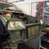
MetroRacing Posted April 26, 2013 Author Share Posted April 26, 2013 Hi all. Thanks for all the comments and to Avro683 for sorting out the tailplane issue as well as pointing out another one with the forward spotlight, which comes too late for me as the halves are together. My answer for the length of time between updates is brush painting is slow, plus I only want to highlight problems in the building of the kit so others can have a heads up. Anyway onto the kit. As mentioned previously the fuselage halves are together. The fit of the interior parts is excellent aswell as the fuselage halves themselves. Jenkin's looks very tall, maybe too tall when seated in the seat. I should also mention that before I closed the fuselage I inserted the tailplanes as whilst test fitting they proved to be a very tight fit. No glue required. Moving on to the window glass, which has been fighting me all the way, use a strong glue. The front windows should not be mouted on the inside as per the instructions. Mount them via the outside. The insert to replace the top turret has two ejector marks on the inside I filled them as I am making AJ-T with the ventral gun. I wouldn't worry about them otherwise. This is the only gap I have in the fuselage, likely caused by the bomb bay end plate being slightly too big. Shouldn't be a problem to fix and easy to prevent in the future. Also because I am building a wheels up version I decided not to add the wheel bay frames to the spars. This allows me to build the wings seperatly and just slide them on, the fit of these parts is very good, not too tight and not too loose. TTFN Ashley. 1 Link to comment Share on other sites More sharing options...
JOCKNEY Posted April 26, 2013 Share Posted April 26, 2013 Great painting job on Guy Gibson by the way Link to comment Share on other sites More sharing options...
Hamden Posted April 27, 2013 Share Posted April 27, 2013 I thought T TOMMY was the spare taken by Joe McCarthy at the last minute due to tech problems with his regular aircraft. Roger Link to comment Share on other sites More sharing options...
Jonny Posted April 27, 2013 Share Posted April 27, 2013 MetroRacing Metro, Iv'e just been looking at the shots of the fuselage together. Is that a black box sitting on or next to the navigator's table, behind the pilot? It's just that it looks a bit like an H2S receiver. Not appropriate for a Dams raid Lancaster. If it is the receiver, can you remve it? Sorry if I have my wires crossed! Jonny Link to comment Share on other sites More sharing options...
MetroRacing Posted April 27, 2013 Author Share Posted April 27, 2013 Hi all. Jonny, I don't know what the black box represents. My knowledge of Lancasters extends to it was built by Avro and it was four Merlin engines. The box is mounted on a stick coming out the top of the table end, it's easy to remove if needed, but again nothing is mentioned in the instructions. So on to this post and more errors in the instructions. As can be seen I've mounted an engine to the wing. The first error is the insert between the top of the outer nacelle and the top of the port wing. The instructions call for F9 however said part is actually F6, F9 being the four engine cooling flaps which are even labelled as such in the instructions. The other problem is that some of the exhaust shroud numbers have been mixed up. F18 should infact be F19 and vice versa, F19 should be F18. I'm beginning to see a clear picture that the majority of problems are in the instructions. Whoever the test builder was needs to be shot at dawn. TTFN Ashley. Link to comment Share on other sites More sharing options...
MetroRacing Posted April 28, 2013 Author Share Posted April 28, 2013 Hi all. A small update for those of you that get caught out by the instructions when mounting the forward spotlight. As mentioned previously the slot should be cut out from inside the port fuselage half before cementing the halves together. The slot should be in the centre of this circle. Mine's slightly off but with the light installed you can't tell. The filler is for the first incision, which was in the wrong place. Also would anyone know if the wheels from this kit could be used on trumpeters Wellington. TTFN Ashley. Link to comment Share on other sites More sharing options...
avro683 Posted April 28, 2013 Share Posted April 28, 2013 The black box is the H2S and needs to go. Also, don't fit the bomb sight as each bomb aimer used their own method. 1 Link to comment Share on other sites More sharing options...
The wooksta V2.0 Posted April 28, 2013 Share Posted April 28, 2013 Don't know about this Lanc wheel's but Pavla do a set of treaded wheels that are rather nice. Link to comment Share on other sites More sharing options...
avro683 Posted April 28, 2013 Share Posted April 28, 2013 Treaded wheels are no good for most wartime Lancs though. Scampton, in particular, was a grass field for most, if not all, of the war. 1 Link to comment Share on other sites More sharing options...
JOCKNEY Posted April 28, 2013 Share Posted April 28, 2013 Avro Are you hinting that our Lancasters were equipped with dodgy polish Remoulds as opposed to threaded tyres ? Link to comment Share on other sites More sharing options...
avro683 Posted April 30, 2013 Share Posted April 30, 2013 Avro Are you hinting that our Lancasters were equipped with dodgy polish Remoulds as opposed to threaded tyres ? not at all, it's just that during the war Lancasters tended to be fitted with slicks, not treaded tyres, hopefully new! Link to comment Share on other sites More sharing options...
kstater94 Posted April 30, 2013 Share Posted April 30, 2013 The black box is the H2S and needs to go. Also, don't fit the bomb sight as each bomb aimer used their own method. Thanks for this bit of info Avro! I'm in the early stages of building my Lanc and was just about to paint it! Guess I'll cut it off and drive on! Any other info regarding what should and shouldn't be installed would be greatly appreciated! Cheers! John 1 Link to comment Share on other sites More sharing options...
chaddy Posted April 30, 2013 Share Posted April 30, 2013 The rear altimeter spotlight is in the wrong place. Link to comment Share on other sites More sharing options...
kstater94 Posted April 30, 2013 Share Posted April 30, 2013 The rear altimeter spotlight is in the wrong place. Where should it be chaddy? Link to comment Share on other sites More sharing options...

Recommended Posts
Create an account or sign in to comment
You need to be a member in order to leave a comment
Create an account
Sign up for a new account in our community. It's easy!
Register a new accountSign in
Already have an account? Sign in here.
Sign In Now