Search the Community
Showing results for tags 'Airfix'.
-
Evening all. I'd like to join in with Airfix's recent small-scale Mossie in its bomber guise. I'm going for the airframe on the box art because 1) I don't need any AM decals but mainly 2) Its the subject of a big poster I had on my bedroom wall when I was a model-mad teenager. Of course at the time, I dearly wanted to build a model of it so its great to now have that chance. Thanks Airfix! Here's the usual box & sprue shots. Here's the poster which I bought from the RAF Museum shop in the late '70s. It is, of course, one of Charles E Brown's wonderful wartime air to air photos. At the time, my friends all seemed to have rather different posters on their bedroom walls. Many involved models but were definitely not de Havilland or Airfix products! I'm planning to build this one out of the box but we'll see how that goes when I get to the bomb bay doors/fairing and the tailwheel. Here's hoping this thread gets further than my last one. I posted the same sort of photos for an Airfix 1/48 Chippy in the last DH GB then found out later the same day that we were moving house imminently. That stalled my modelling until now. That move went well so I'm confident I can actually start building this time. All the best, Phil.
- 18 replies
-
- 10
-

-
 Gonna add an Indian Spitfire to the Indian Tempest. Would have preferred to do the camouflaged "96" with the Chakra roundels. There are Iliad Design and Model Alliance decals for this scheme, but the Chakras are on white ground. Actual info is that the chakras on camouflaged aircraft were on yellow ground. So gonna do the silver Indina scheme with the normal cockades included in the kit. DSC_0008 by grimreaper110, auf Flickr DSC_0009 by grimreaper110, auf Flickr
 -
After some prevarication I think I'd like to put this into the group build.... I got this as part of an auction bundle of car kits and would very much like to get it done. But there's a problem. I made a rudimentary start back in December, assembly of the main bodywork parts, then quickly realised that several key components were missing. I have no instructions but I found the required document on Scalemates.com, no problem. But study of the drawings showed that I have no chassis parts, rear axle or suspension, or front axle arrangements. It was like someone had built up the chassis assembly and then put it on a shelf while the rest of the kit stayed in its box. And I got the box! I think I have the wherewithal to try a scratch built solution and the added impetus of being in a group build might just be the motivation to see it through (or fail gallantly 🤩) Here's what I've got... And this is the basic shell with the petrol tank attached to the rear... That's well under the 25% threshold, I'd say, although if the hosts say otherwise I shall reconsider my choice, of course 😉 It'd be great to get my little MG sorted out
-
Hello Everyone, While parts for my Type 45 destroyer build we're drying, I decided to make a start on another kit from my stash. At my wife's insistence, I started work on an Airfix 1:72 scale Red Arrows Gnat which has been sitting in the stash for a while. I will post sprue photos later along with the 1st construction photos. I'm working on simple builds while my destroyer is drying etc. All the best, Rick
-
 Expected in Spring (May ?) 2024 - ref. A09010 - Consolidated B-24H Liberator https://uk.airfix.com/products/consolidated-b-24h-liberator-a09010 V.P.
- 205 replies
-
- 46
-
-

-
 For this GB I'm going to build a "Sexy American Singles in South American Service" subject, a Bolivian P-51D. Sexy American Singles in South American Service involves building American WWII single-engine aircraft to represent eight South American nations. So far, I've built representatives from Chile (A-24B); Argentina (F4U); Brazil (P-47); and Uruguay (F6F). Bolivia will be the next addition. I had hoped Arma would have their P-51D out by now, but since they don't I'll use this Airfix kit I picked up. One day I want to build the Korean version from it, but for now she'll be Bolivian. I will use decals and the profile from Aztec:
- 26 replies
-
- 10
-
-
Hi, on this group build I'm moving back to my preferred scale and also to the beginnings of NATO, and I'm building an Airfix 1:48 Supermarine Seafire F.XVII (A06102A). It is all too easy these days, seeing Leopard tanks and F-35s being presented in NATO social media posts, to forget that NATO was founded soon after the WW2 and thus most weaponry, aircraft, tanks and vessels included, that was used by NATO nations in those early years, was of similar vintage. Here is the box: It is a big box, and it contains big parts, which is a personal relief, having just built three models in 1:72... Speaking of parts, here they are: As you can see, I'm using aftermarket parts for masks and cockpit decoration. I plan to build the version on the box, from the No.767 Naval Air Squadron, Royal Naval Air Station Yeovilton, Somerset, England, 1950. /Jari
-
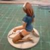 Not a full set, but a restoration. Summer dress Winter dress with a sepia wash
 -
 Hello Britmodellers, Here's my take on the Airfix MiG 17. I wanted to build a slightly different machine than the famous '3020' so I did some decal juggling there. A few grainy pics show '3012' in a heavily weathered condition. It took me two tries before I ̶g̶o̶t̶ ̶f̶e̶d̶ ̶u̶p̶ ̶w̶i̶t̶h̶ ̶i̶t̶ / got the effect somewhat acceptable. Other modifications were the KK-2 bangseat, reshaped inner wing leading edges and brass gun barrels. Thanks for watching! Luka
- 11 replies
-
- 42
-
-

Austin Healey 'Frogeye' Sprite - +++ Finished +++
CliffB posted a topic in Baby Boomers GB 1946-1964
Hi. Here's another one from me. The Frogeye Sprite (aka the Bugeye in the States), was produced between 1958 and 1961, and utilised the 948cc engine from the Austin A35 and Morris Minor 1000. Whilst the A35's engine produced around 35 BHP (the clue's in the name), for the Sprite this was boosted to 43 BHP. This gave a top speed of 83 mph and a 0-60 mph time of 20.5 seconds. For its time, the car was pretty nippy and went on to provide an affordable way into motorsport on both sides of the Atlantic. The Airfix kit was first released in 1961, but mine's a '90s release. All my parts are still factory-sealed, so I'll open things up for a closer look, once I get started. Where possible, I like to base my car builds on real, preserved examples and I'll be using this beauty for this one. Cheers- 36 replies
-
- 20
-
-
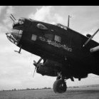
North American B-25C/D Mitchell (A06015A) 1:72 Airfix The Mitchell was a twin-engined medium bomber that served with distinction during WWII, with over 10,000 being produced by war's end. Named after General Billy Mitchell, the type reached prominence early on in America's entry to the war, as it was used in the famous carrier launched Doolittle raid on mainland Japan, leaving USS Hornet to bomb Japan, and attempting to land on fields in East China after the mission. It was a good aircraft to fly, and was well-liked by its crews, as well as being able to soak up a tremendous amount of punishment from the enemy and still remain flyable thanks to its rugged construction. These traits led to the Mitchell being used in almost every theatre of war, and in addition to bombing duties it was also converted to a "gun-truck" for ground attack, and was fitted with various armaments, including cheek mounted machine guns in fairings, and sometimes the 75mm cannon from a Sherman tank in a solid nose cone, as well as four .50cal brownings in the nose (B-25G) that was named ‘Strafer’, plus the turret guns that could be aimed forwards to add to the hail of munitions. The J-model was the last production variant in a long line of upgrades and improvements, and although many were built with glass noses, they were often converted in the field to a solid nose for ground attack duties. The Kit This kit was first released in 2018, and this boxing adds new decals to the existing tooling and new box art to match, depicting a gaggle of Mitchells flying low over desert terrain. Inside the box are five sprues of different sizes in dark grey styrene, two clear sprues, decals, and the instruction booklet, which is printed in colour with decal option profiles on the rear pages, accompanied by a separate page of profiles for the common stencils applied to the aircraft. Detail is good, and this 1:48 modeller was quite surprised by the small size of the Mitchell at this scale, probably because I’ve been handling a 1:48 B-25 kit recently for another review. It includes a detailed cockpit, bomb bay, turrets, and gun position details, with options for dropped or retracted flaps plus poseable tail surfaces, and raised or lowered wheels to add some personalisation to your model. Construction begins with the cockpit, based on a stepped floor, to which the twin control columns with integral centre console is added, with the instrument panel in front, applying a decal to depict the dials. A bulkhead is fixed to the front of the floor, and two crew seats are slotted into sockets in the floor behind the controls. Another bulkhead is slotted in from the side behind the crew, and an additional lower floor part it fixed to the bottom of the assembly after drilling out two flashed-over holes in one side. At the rear of the assembly, a further bulkhead with moulded-in spar is mounted, then the nose compartment is detailed with a small seat and a bicycle-like seat in the very front of the floor. The bomb bay is just behind the cockpit, and the fuselage halves are thinned here to accept the bay wall inserts, which also have the bay doors moulded-in to give it a strong join, and is detailed with the bomb ladders down the sides of the walls. A note in this step tells you to skip ahead if you plan to leave the bay doors closed, which I missed initially, so make sure you don’t. The cockpit assembly is installed on the port fuselage after detail painting, sliding it into position by feeding the spar through a hole in the side of the fuselage. Another spar is prepared with an extra layer to the bulkhead, located on circular pads, then it too is slipped into the port fuselage, adding 25 grammes of nose weight under the cockpit, making use of the box-like structure there. The bomb bay roof is fitted between the two bulkheads, and an insert is added to the belly behind the bomb bay with the socket for the belly turret and its pivot point moulded-in. The bombs are provided in this boxing, making four of them from three parts each, and gluing two on each side of the bay, adding retraction jacks and their mounts to the front of the bay opening. With both sides of the bay built and painted, the fuselage halves can be closed, and the seams dealt with in your preferred manner. If you elected to leave the bay doors closed, a separate part is included with a panel line down the centre to represent the two doors closed against each other. The wings are built on the spars projecting from the sides of the fuselage, adding the upper surface first, and installing the clear landing light lenses in the leading edge, drilling out some flashed-over holes, which are used to locate the aerodynamic fairings over the exhaust ports on the trailing edges of the wings. The lower surface is then glued in place, two clear inserts are fitted into holes in the fuselage sides behind the wings, which cater for various window arrangements through the different variants, and should be test-fitted carefully so that they are level with the rest of the skin of the model. The elevators are built from top and bottom halves with separate flying surfaces trapped during gluing, which can be deflected according to details given as the assembly is glued onto the rear of the fuselage ready for the rudder panels to be built. Again, the panels are made from two halves with separate rudders, one per side, and these too can be deflected according to the numbers given on the diagrams, plus another diagram that confirms that the rudder panels should be posed at 90° to the elevators. The next choice is whether to pose the gear up or down, with gear down the first choice to be described, starting with positioning the main gear legs, using the outer nacelle half as a jig to locate the strut, but not applying any glue to the nacelle part at this time. It can be left in situ while the glue on the gear leg cures, and in the meantime the engines and their cowlings can be made, which are common to gear up or down options. The front row of pistons has a central axle trapped between it and the reduction bell-housing at the front, then it is glued to the combined bulkhead/rear bank of pistons, providing detail that will be dimly seen through the spaces between the front bank of pistons, and via the cooling gills at the rear if you have sharp eyes. The cowling is prepared by adding seven small raised fairings around the main part, sliding the completed motor into the back of the assembly before fitting the cowling gills using the tabs and slots that are shown in the diagrams. The nacelle halves are joined together, assuming the glue has cured on the main gear legs, and these two parts are augmented by a short forward section on the outer half, then mounting a bulkhead and intake to the front, repeating this for the other side in mirror image. The completed nacelles are then lowered over the main gear legs and glued onto the underside of the wings. For the gear-up option, the legs are omitted, and the small curved bay door covers the opening before gluing the nacelles to the wings, removing the two hinges from one end first, which is done again in mirror image for the opposite engine. The engine cowlings are then glued to the front of the nacelles, regardless of the gear option chosen, then the two flap sections per wing can be glued in place lowered, or retracted by using different parts, doing the same on the opposite wing. Both wheel position options have the curved bump-stop at the very rear of the tail, then for the gear down option, separate scissor-links are glued to the legs, adding the doors and a retraction jack near the front of the bay. The wheels are each in two halves, and have a diamond tread pattern moulded into them, so take care aligning the halves once you have applied glue to minimise clean-up. The attachment points on the struts are specially designed to prevent mistakes, so check that the inner peg is aligned with the hole in the bottom of the tyre cut-out before you leave the glue to set. The Mitchell was unusual for a WWII bomber because of its tricycle undercarriage, and for gear-up the bay is covered by a small door that has been reduced in width prior to fitting. The gear down option has the strut inserted into the slot, a translucent scrap diagram showing how it should locate, then the uncut door is fitted to the edge of the bay, adding the wheel with separate outer hub to the bottom of the leg. The belly turret could be retracted so that it was almost flush with the airflow to increase speed and reduce fuel consumption whilst on the way to and from enemy territory and for landing. You have the option to pose it in either position, gluing the two machine guns into a different centre mount, depending on your choice. Both options are then inserted into the clear upper section of the turret, installing both in the cut-out under the belly, the mount holding each option at the correct attitude. The deployed turret clips into position without glue thanks to an expanding spring clip on the mount, but it is a one-time use clip, so make sure you’re ready to install it, and don’t be tempted to put it in early to see how it looks. The retracted turret has its guns aligned with two long recesses, so can be glued into position as there is only one possible position for them. Behind the turret is a crew hatch, which has four tabs around the lip that can support the door if you intend to leave it closed. To open it, the tabs should be cut away, fitting the combined door and ladder to the front of the cut-out, with the same process carried out on the door to the front of the bomb bay. The upper turret is next, fitting the twin machine guns to the central mechanism, and trapping them in position with another part of the assembly. The two ammo cannisters with a twin feed of link is glued to the front of the assembly, then the completed assembly is inserted carefully into the glazing, a scrap diagram showing how it will look from below. The completed top turret is then fitted into its cut-out, locating in a socket in the floor inside. The nose is open at this stage, allowing you to install a rack of ammo cans, plus the gun that is offset to one side of the bomb sight, which is another part fitted to the front lip of the floor. Under the nose is a small window that is inserted from below, then the top glazing is added, followed by the nose glazing, which has a flexible mounted machine gun pushed through the central hole, slotting the fixed gun through the other offset hole in the clear part as you install it. There are two styles of canopy included on the sprues, one for each of the decal options, and at this stage you can choose to seat the two pilot figures that are supplied or not. An astrodome is added to a hole in the fuselage behind the cockpit, fitting two landing light covers in the leading edges of the wings, installing some windows in the sides, and the glass dome in the tail. The final few parts dotted around the airframe include pitot probe in the port wingtip, two antenna masts on the spine, plus a D/F loop in an aerodynamic fairing, and the twin three-bladed props, one in each engine nacelle. Markings There are two decal options on the sheet, one in US service in a desert scheme, the other a lend/lease aircraft in Soviet service, each with a full page of profiles to help you complete the task. An additional page of profiles shows where the stencils are applied to both decal options, using line drawings to simplify the process. From the box you can build one of the following: B-25C Mitchell ‘OH-7’, 41-13207, 445th BS, French Morocco, 1943 B-25D Mitchel ‘09’ 42-87594, 1st Sqn., Uman Airfield, 1944 Decals are by Cartograf, which is a guarantee of good registration, sharpness and colour density, with a thin gloss carrier film cut close to the printed areas. Conclusion A nicely detailed B-25 in this scale with plenty of personalisation options that belies the scale, with a couple of interesting and more unusual decal options, which combines to make for a welcome re-release. Highly recommended. Review sample courtesy of
-
My first kit in over 50 years. Thoroughly enjoyed it. Made some mistakes but all part of the fun! For a starter kit I was impressed by the quality of the fit.
- 10 replies
-
- 32
-
-
-
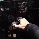
With the Jet provost done and the other activities out of the way, it’s time to get back in the saddle and do some more modelling. For a bit of a mojo boost, I watched Top Gun, Top Gun Maverick and The Final Countdown on DVD’s. So tonight, out came the Airfix F-14A Tomcat (blueprint box) and the Revell F-14D Super Tomcat from the stash - both 1/72. I’m going to try to build them both together stage by stage (rather than build one and then the other). The Revell is better in detail as it’s a much later kit, but the Airfix one still has a certain charm to it - even with the raised panel lines which I’ve decided to leave to see how it turns out. So, the first stage was to build the two cockpit tubs. The Airfix one is much longer then the Revell and both have raised detailing in the some consoles in roughly the same depth. The ejection seats are worlds apart in detail, so I might see if I can 3D print something a little more interesting for the Airfix kit. Otherwise the offices are fairly well detailed considering….. Both tubs were painted with Tamiya XF-19 Light Grey (as it’s what I had to hand) and are drying off. They will both receive other colours to highlight the consoles and IP’s. I’ve also bought an extra set of Airfix F-14A decals which offers two options - TopHatters and the Black Aces - to go with the Bounty Hunter and Grim Reaper options for the kits.
- 44 replies
-
- 12
-
-
Back in 2011 I saw that Airfix had announced a Valiant and so I put in a pre-order and waited - probably for around 6 months. Eventually it arrived but has been gathering dust in storage ever since. It was issued too late to be eligible for the Airfix Classic GB but is I believe eligible for this one and also the NATO one later this year, so if I have time I will have a shot at building it. Airfix describe it as a BK Mk 1 though I am uncertain if that is correct as initially the Valiants were pure bomber B Mk 1 I believe. Some were later converted to a PR version, and others to a tanker and in 2012 Airfix released a conversion pack for both of these versions, and in 2021 I understand that they released a re-boxing of the kit complete with at least part of the conversion set. Perhaps the nomenclature was changed to recognise the fact that the bomber could be relatively easily converted to a tanker and back again, but I will be building it in the bomber configuration, perhaps in the all over "Anti Flash White" scheme as I remember seeing them flying high overhead once or twice on my way home from school in the early 1960's. The Valiant entered RAF service in October 1952, and was phased out in 1965 shortly after the switch from high level to low level as the wing spars were found to be suffering from metal fatigue. The Valiant was considered something of a stop-gap design and so as the "more advanced" Victor and Vulcan had entered service by then it was apparently decided not to bother repairing the Valiants, and the B2 low level version was not ordered into production. The kit comes with markings for 4 aircraft - the second prototype WB215 in NMF, XD823 used in Operation Grapple to drop what was claimed to be the first UK hydrogen bomb in 1957 (there is some doubt about whether or not it was a fusion event rather than a fission one I believe), XD857 in 1963, and WZ404 in 1964, and has the option of either a single nuclear weapon or 21 x 1000lb iron bombs, though I will probably model it with the undercarriage down and the bomb doors closed. I suspect this was one of the first of the "new style" Airfix kits, following their Bf 110 of 2010 so it will be interesting to see how it goes together compared with some of the more recent ones. Pete
- 36 replies
-
- 18
-
-
With a Japanese nightfighter finished, I thought I’d try an allied machine as well. The Blenheim isn’t as popular I thought it would be, so I’ll add a Mk IVF. Maybe I’ll go with the one on the box cover, unless I can scrounge some serials and codes for a plane in navy colours. Or maybe not. Will do some research, found seceral titles on Scribed. The box: I built the old Airfix as a kid and remember struggling - I expect this to be a bit different. The box contains pieces to do a regular Mk. IV as well, so that is another possibility. Assembled the office - will try to paint it all in one piece. I’m masking the lower window to paint it on the inside as well. The rest of the glass house I’ll paint only from the outside. It’s very thick anyway. This is the first Airfix model I’ve seen where the flaps can be left lowered, with moulded structure inside. Thickness of braces is of course widely overscale. Will see what to do. Some internal structure in the wheel houses too: Fit seems good, but the soft plastic has quite rounded edges, which results in trenches where the pieces mate. I expect some filling.
-
The Airfix Blenheim has been built a few times in BM and I previously built a both a MkI and a MkIV of 771 NAS based at RNAS Twatt. So a quick look in the stash revealed this one as well. I had laid down some paint previously but that’s all. I have some aftermarket, the masks are vital for the Blenheim’s glass house and turret, while I’ve got a selection of transfers. I’ll use the markings for 787 NAS the Naval Air Fighting Development Unit. I’ll add in some etch seat belts but otherwise OOB.
-

Gloster Javelin FAW.2 - XA801 1/48 - Airfix
Mikey-1980 posted a topic in Work in Progress - Aircraft
Morning all! My first memory of pretty much any aircraft as a child was seeing the odd shaped Gloster Javelin that was the former gate guardian of RAF Stafford. My dad was stationed there from 1982 - 85 before demobilising. The airframe was then later scrapped due to poor maintenance in 1994, as seen here in the video below My plan is to build XA801 and convert the Airfix FAW.9 to the FAW.2. Problem is, I cannot find the conversion kit needed to do so. I know there are only a few slight changes between the FAW.2 and the FAW.9, the most notable is the engine exhaust, as well as the FAW.2 did not have mid-air refueling. I know that a conversion kit exists, but I cannot find it anywhere, if any one is able to help point me in the right direction, or knows someone who has one that are willing to part with it, I would more than interest. Thanks all in advance -
 Hello Everyone, This one is going to be my main project. I was recently sent this kit by a very good friend of mine, who knew that I wanted to build another one especially after I saw the last James Bond movie, No Time To Die. I have previously built an Airfix 1:350 Type 45 destroyer kit as HMS Daring when the kit was first released and had always meant to build another one to go with my few other Royal Navy warships models (HMS Illustrious, HMS Turbulent, HMS Astute). This build has not been started yet (except for washing and priming the sprues), so I will post some photos of the untouched sprues and then include photos of the various build steps as I go along. I will most likely start the painting and building process tomorrow. All the best, Rick
 -
My last Airfix Mustang in the stash. I found some goodies too. Although the red-tail markings are attractive, I once fell for the luxorious design of these Exito decals, and I somehow need to motivate that expense, so this will be the choice this time: It’s a P51D-25-NA operating as long-range escort out of Iwo Jima towards the end of the war, and since I have 5-, 10 and 15-NA since before it complements the collection. Some tweaks will be needed, regarding radio equipment (I distinctly remember they had a different set of boxes, not to mention the different set of antennas) and tail-warning radar. I now have one week to find that vac form canopy and Quickboost exhaust stacks I remember buying but cannot find. I now understand how squirrels feel.
- 13 replies
-
- 13
-
-
A third entry, and for me an iconic Baby Boomer, following the release of the film Goldfinger, the Corgi version of James Bond's Aston Martin DB5 became the must have toy back in the mid-60's. For this build I am using the 1/43 Airfix starter set version which should make up into a nice little representation of this classic Grand Tourer, by John L, on Flickr Here are the main sprues, by John L, on Flickr and the clear parts decals, paints and glue. by John L, on Flickr John.
- 19 replies
-
- 18
-
-
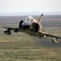
This is AK431, a workhorse from the North Africa campaign, based in Fayid, Egypt in 1943. With its battered, leaky exterior, this P-40 looks like the survivor of a tough environment. The Airfix Tomahawk is a nice kit - easy to build with a nicely detailed interior. I added a Master gunsight and replaced the pilot with the one I didn’t use from the Tamiya P-38, a well sculpted figure that deserved to be reassigned. Apart from an unfortunate Me-109 I mauled as a 10-year-old, this is the first desert scheme I’ve attempted in the second phase of my modeling career. Another first was attempting some riveting, as well as using Mission Model paints, which layer nicely when thinned down considerably. Forgive my amateur Photoshop experiment with getting this thing to fly. Well, under the circumstances, you’ve got to keep yourself entertained. Thanks for looking.
- 34 replies
-
- 62
-
-
-
I'd like to enter with this please; Bought a few years ago, along with the Airfix Curtiss Tomahawk, each costing me the princely sum of £2.49! The Mustang is my all time favourite aircraft, and many moons ago I built the Matchbox and Academy 1/72 P-51Ds, so it will be interesting to see what this much newer kit is like. It certainly looks nice upon initial inspection; Mine actually came with two sets of decals; This RAF scheme is nice, but its not how this one will be finished. Back in 1995, when I built the previous two Mustang kits, I had just started to get interested in the Eighth Air Force, and, whilst on holiday in Suffolk, had recently visited my first old airfield, which happened to be Leiston. Ever since then, Leiston has been a bit of a special place for me. Ended up visiting Hannants, and buying some Repli-Scale "Yoxford Boys" decals. The Matchbox kit was finished as "Old Crow", and the Academy as "Glamorous Glen III", which leaves me with these options: I'm thinking of going for "Missouri Armada". The decal instructions show this as an early model D, but I consulted this; There is a photo of Missouri Armada showing it with the fin fillet. The serial number given on the decal sheet (414709) is not amongst those listed at the rear of the book, however 414789 is, which is only 1 digit different. Using other numbers on the sheet, I can cobble together the right number for the model. Time to saddle up and get started!
-
I'd built the Airfix Valiant quite a while ago and it was interesting to note the advances made by the company in the 5 years or so between the two kits being released (2011 - 2016 according to Scalemates): a clear step up in refinement and build quality, which they've continued pretty much ever since. Next on the production line is the Vulcan so I'm looking forward to see how it stacks up against their much more recent releases. The size & shape of the Victor makes it hard to photograph, let alone display but I'm quite pleased with how it turned out. Thanks for looking, J.A.
- 19 replies
-
- 77
-
-
-
Another more recent completion of an old kit--this Airfix kit was from 1970 and I finished it in July of 2023. This may be the oldest kit I've built and there were no issues in the build quality. Unfortunately, one small piece was missing from the bag it came in (see if you can tell which one). I painted this in the pre-war Splittertarnmuster scheme using AK Real Colors' line (RLMs 61, 62 and 63 with 65 (1938) underside) The lines came out extremely smooth and better than I expected. No issues with the decals either, though this kit did not contain any swastikas for the tail. I don't have a place near me that sells these either (and shipping to Canada for anything is outrageously expensive), so I've left the space empty right now. Maybe one day I'll pick up a sheet of swastikas (there's a fun sentence) and throw a nice red banner on the tail. ----------------------------------------------------------------------------------------------------------------------------------------------------------------------------------------------------------------------------------------- he Hs 123, designed by the transportation company Henschel, was a German dive bomber and close air support biplane, used during the Spanish Civil War and much of the Second World War. Though originally intended as a dive bomber, the Hs 123 was overtaken quite early in this role by the Junkers Ju-87 Stuka, the latter having much better range, and larger bomb capacity. Due to this, the Hs 123 was transitioned into a close air support role, where it did quite well. Production was short-lived however in favour of the Stuka. The Hs 123 was used during the initial invasion of Poland where it could drop bombs very accurately, and the sound of its engine was apparently quite terrifying to hear (if the threat of being bombed wasn't enough, I suppose). It was considered a very effective aircraft and would be used by the Luftwaffe during the Blitzkrieg and later on the Eastern Front. Apparently Colonel-General Wolfram von Richthofen requested they be put back into production as late as 1943 due to their reliability in poor weather conditions which could ground more advanced aircraft.
-
 Hi folk's should be enought time to do another 1/48 build for this GB so instead of the common sense route of Tamiya's offering's I'll head back to Happy childhood days and Airfix's at the time much lauded release.KK have a dozen in stock so not sure which boxing will arrive if the decals are unusable AM will be bought.
- 44 replies
-
- 17
-