Search the Community
Showing results for tags 'scratchbuild'.
-
 Hi All, Here we are following on from the 1/32 Malta Gladiator by far my best build so far. With the next build, I've decided to do something more challenging, creating an almost extinct inter-war torpedo bomber in a scale never seen before... I give you the 1/32 Vickers Vildebeest, this aircraft was a design that first flew in the late 20s and managed to cling on until the early parts of WW2. It's a all metal structure bi-plane covered in fabric and from a CAD design point of view a head-scratcher... as very little info remained from that period hardly any drawings survived and only two fuselages both in NZ survived one Vildebeest and one Vincent. so I started designing the fuselage around 2 years ago mucking about with line drawings off Google and managed to get a basic representation of the shape i have now improved this into something I'm happy with, 3d printed resin is great for detail but can warp, it is very fin so that has been something i have had to design around. after already printing my original fuselage and not being happy with the results I redesigned the fuselage and got a 1/72 special hobby kit for reference and to check scales which to my surprize were pretty good!! this image shows the scale of the vildebeest very large for a single-engined aircraft CAD Model of the RH fuselage size prior to being sectioned for printing. Here are the prints of both halfs ready to have supports removed and assembled. first mockup with the engine (Bristol pegasus from Vector resin). First print of the floor. A lot of work is required yet I'm currently trying to get the interior and cockpit complete and fuselage glued before the exterior gets a lot of attention. The fuselage frame is constructed from styrene rod with 3d printed fixings. Some of my hall from Telford included airscale PE and decals which should make it all come together. small prints such as levers and bellcranks are visible from the side windows so I have modelled them this print wasn't perfect but the parts were useable. thanks to a generous member of my local model club (Thanks Simon) for lending me some images and info he had for this aircraft one of the most valuable items was a rare instrument panel drawing which I have modelled will be improved with the airscale goodies, the extra bit at the top is due to the different profile of my fuselage but this should be hidden once the model is complete. If anyone has any questions I'm always willing to try and answer them the best I can. Thanks James
 -
Happy 75 Birthday NATO 🇩🇰 It is probably true to say that there is no organization in the world that I admire more than NATO. I don't want to go into depth why since I might just get a bit 'political' and we cannot have that here, but I am prepared to say that - in my belief- if NATO had not existed for the last 75 years, the world would be a much more dangerous place and many fewer people would enjoy security and freedom.With this in mind I think I have no choice but to take part in this most excellent group build. I really like the idea of the flags! It's unique and intriguing and might just give an incentive to folks to model some of the smaller nations that might sometimes be overlooked. ‘My’ flag is The Netherlands; however, try as I might, I cannot find a Dutch subject that grips me quite as much as a Royal Danish Air Force F-100D! Yes, a Super Sabre complete with grotty, patchy, olive-green, livery! Admit it... you know the kind of filth I mean! Another reason to pick the Danish Air Force is that a friend of mine who collects models lives just 5km outside of Denmark and yet has not a single Danish item in his collection. (In the interests of transparency I should probably point out that I am referring to 'Denmark' the small coastal Western Australian township rather than 'Denmark' the Scandinavian constitutional monarchy - but you get the idea). I really like the F-100! It just looks so damned mean. It has to be the most shark-like looking aircraft ever made and its relatively simple geometry makes it a great subject for scratchbuilding. When I was a teenager I scratchbuilt one in roughly 1/100 scale and it came out OK, but it did not survive the various parental 'junk purges' that punctuated my many years living away from home and now - alas - it's in landfill someplace. Never mind, let's just make another one... a bigger one! Here are my references... some inspiration... and the raw materials! I'm hoping this will be a good chance for me to practice and improve on many of the methods that i used for the first time during my - still ongoing - Mirage IIIO build. This project I'm hoping will be relatively simple. Much of its success or failure will depend on the final painting and weathering as I'm hoping I can make this look like a jet as battered and worn as those in the pictures above. But let's start at the beginning. As usual I have selected Jarrah for the fuselage and have used cheap photographic spray adhesive to stick the relevant plans on the side. Here is the very first cut of the entire project. Shockingly that's not a bandsaw, but don't worry I will be using one very soon. OK - here it is, the first bandsaw cut! Let's call this the moment that the ‘project proper’ begins. To get to this shape does not take long. After some sanding and general tidying up we have this... Which is only the starboard half of the fuselage. I will be cutting out the port side tomorrow night. I have absolutely no hope whatsoever of finishing this project within the allocated four month timespan, especially since this new build must compete with the ongoing Mirage project which must be finished by August 2024. Nevertheless I do think that in the limited time available I can probably bash together sufficient shapes so that it is unmistakably an F-100. Following that I'll just transfer this thread back to the 'main pages' and carry on to the end. In the meantime I hope that this is of interest to you NATO enthusiasts and that you can all get some enjoyment out of watching my humble attempt to turn out a Danish Hun. Go Team NATO! Bandsaw Steve
- 23 replies
-
- 25
-

-
- RDAF
- Scratchbuild
- (and 1 more)
-
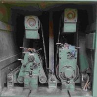
My workshop has temporarily limited operational capabilities: the paint shop is closed due to numerous equipment failures. I wrote a letter to Santa Claus, demonstrating beyond any doubt that I had been good all year long and deserved a brand new, shiny airbrush. My wife promised to deliver the letter to the addressee. Therefore, there is reason to believe that one of the hardware problems will be solved in the last days of December 😉. There is still the issue of compressor repair, which unfortunately is going worse. Anyway, I can't paint old things for now, so I started building new ones. A construction mech has been on my mind for a long time: an excavator or some sort of demolition machine from the near future, with legs instead of tracks. The thing is supposed to be in the mecha style: a robot with an operator inside. I'm not sure that mecha doesn't only apply to armed vehicles, but I don't feel like making another military thing. Make walls, not war 😉. Construction started about two weeks ago. This is the operator's cab "kit": plastic cosmetic jar and acrylic Christmas bauble. I have several such baubles. This is a semi-finished product for making your own decorations. It used to be perfectly transparent, but I dulled it with sandpaper. For now, I only want to use half of the bauble. I glued the HIPS floor inside. This can be seen, although somewhat blurred, in the photo below. Several rings of different shapes will form the control panel around the operator's seat. On the lower right is the front cockpit panel. I glued this to a piece of a photo etched part that used to be the tank's mud guard. The operator's seat is carved from 3mm thick HIPS. First steps to building the leg drive module. And the first steps in building the legs. I decided to connect the operator's cab and the drive module with neodymium magnets. On the one hand, it will facilitate further construction and painting, on the other: the cabin will be able to be rotated around its axis. From my experience, glue is not enough to properly attach the magnet. The most durable method is to attach it using Milliput, preferably in such a way that both magnets are separated by the plastic to which they are attached. This is what the cabin module, connected to the drive module, looks like at this stage. The jar made from polyethylene was sanded and covered with a HIPS strip. I want to avoid a mishap as when building a spaceship for Above Karman Line GB. There, I skipped the step of covering the polyethylene with polystyrene and ended up with peeling paint. Thanks for watching. Wiesiek.
-
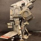
Here we go again. Are you sitting comfortably? back in October at the Lincoln model show, I was taking a slow march around the tables in the company of @general melchett. Under one of the tables I spied a Revell Rotodyne box, the reissue one, up for a tenner. I'd wanted one for some time, so... Of course this won't be built as intended. But then you knew that didn't you? In one of the Star Wars films a sort of flying bus lands and out steps Ewan Mc Gregor. Hmmm A couple of years ago at the car boot I picked up a display type pod racer for a quid. Hmmm The disassembled pod racer. I've wanted to use the engines on something since I bought it. But, I thought they may not be space going engines, hence the pod racer use. All I needed was a suitable fuselage... How to disguise the fuselage source? Well, I had this 1/32nd P-38 nose piece.. So I sawed off the Rotodyne nose. A bit. The nose cone was slightly too narrow, so I sanded down the fuselage halves at the front to fit. But it was then under strain. So it also got sawn behind the door and card inserted . Much better. You can see here the start of trial fitting fairings, The main rotor fairing had to go, of course. These two black bits are ex SR-71. This will not be a bus, but a fast planet bound freighter. Sort of a much much faster DAF 7 1/2 tonner. Here I'm starting to fill in the windows. There's a 1mm card backing plate glued inside them. Filler has since been used. The card inserts seen here save filler and mean that when sanded I should get a fairly smooth finish. The rivets are going too! The fuselage half locating pins were hopeless. I've added card tabs like on a vacform for strength. And, just to prove that I do like the Aircraft. This hangs in the manshed. Rescued from a Calendar almost 40 years ago! The original is signed Hardy and dated 1984. A lovely picture IMHO. Obviously more is to come. I hope you were able to follow my ramblings and will return sometime soon. If only to try and make more sense of what I'm trying to do here. Given the weather, there could be an outdoor bar by then. Who ordered the cheeseburgers from the barbie? Comments and a more exotic cheese in the burgers are always welcome. Cheers, Pete
- 32 replies
-
- 22
-
-
- Star wars
- Scratchbuild
- (and 1 more)
-
 I'm back with another adventure, a 1:48th scale model of the first ever destroyer in the Royal Navy, HMS Havock of 1983 Following the trials of HMS Lightning (torpedo boat No 1) navies around the world began constructing torpedo boats to launch the new Whitehead torpedoes. To counter the threat of these torpedo boats torpedo boat destroyers were commissioned, capable of fast speed (for the time) and with guns capable of eliminating the threat. This is nicely summaried in this video for those interested Yarrow and Thornycrofts were the first builders to enter the race to build the first TBD's with Yarrow launching the first of the new A class 27 knotter's, HMS Havock in 1893 The A class vessels were all different, some having bow torpedo tubes, some not, with varying boiler arrangements (that technology was changing very fast in the 1890's) and differing level of equipment and guns. HMS Havock was one of the early smaller vessels being 180 ft between perpendiculars and 185 ft overall length, displacing 275 tons fully loaded. She had 3 torpedo tubes and 1 12pdr 12 cwt QF plus 3 6pdr Hotchkiss QF deck guns Here she is as originally fitted with locomotive boilers And the builders model I've already posted, also @1:48th scale So, its a big model, 46.25 inch long but very narrow and not too tall. It will make a nice comparison to HMS Medea, the black painted M class destroyer I built 20 years ago. After my loft room sort-out, I now have the space to display it, so here goes.... As ever, I will be building the hull in wood plank on frame with aluminium plating and brass fittings. Where ever possible, wood for wood and metal for metal While the dolls house is developing, I will be working on the drawings and have enough information gathered now to start the thread, though it may be slow to begin with. The key decision to start recording the build came on Friday with a copy of the as-fitted drawing from the Maritime Museum archive. I'm not allowed to post it here but Lyon's great book on early destroyers has a copy and this is a scan This scan does not do the plan any justice, here is a sneak of a piece of the full 84mb file For those of you how have not had the opportunity to work from builders drawings, you are missing a great pleasure. Victorian builders drawings (in particular as-fitted ones) are a delight, they took the trouble to draw more or less everything, the drawing even lists the small arms carried in the captains locker... No model plan comes close To supplement this wonderful plan, here are a few other references I have to help me along the way So, the journey begins, more soon Cheers Steve
 -
Happy Birthday Royal Australian Air Force Today is the 100th Anniversary of the formation of the Royal Australian Air Force. I am not going to write much about the history the of the RAAF because I am no expert. Suffice to say that on this day 100 years ago this service was formed as an independent air-arm and it has strong claim to be the second such service formed anywhere in the world. It has been a cornerstone of Australia's security and this region's stability ever since. The RAAF played an active and effective role in the Second World War as well as numerous 'smaller' but still very significant conflicts, including Korea, Vietnam, the two Gulf Wars and Afghanistan. It has assisted in many peacekeeping and security operations around the globe and has played an important humanitarian role in innumerable civil defence emergencies. At one stage, immediately after World War Two, the RAAF gave Australia the fourth largest national air arm (by number of operational aircraft) in the world. We Australians, and our various allies should be most grateful for the service that the RAAF has provided over the last century. Three years ago I started my build of an Avro 504 to mark the occasion of the formation of the Royal Air Force. Now, it would seem wrong of me not to do something similar for the Air Force of my adoptive homeland. I've been planning for this for a while and was hoping to have at least one of my three other threads on Britmodeller closed by now, but that has not happened. Time waits for no-one and if I'm going to do this to mark the anniversary then I have to start today; ready or not. If we are going to 'do' the RAAF - let's pick a good subject. Let's look at something fast... perhaps even supersonic. Hmmmm... how about a swing-wing thing...? 🤔 Nice idea! But do you know how big one of those things is in 1/32 scale? My display cabinet is only so large. What about something American with a big droopy nose, two big burner cans tucked in under a single swept back tail and tailplanes set an an outrageous angle of anhedral..... 😀 Again, Nice! But that's a very complex shape and I want to finish this before the next 100 years passes. What about something French and triangular that I once saw when I was a lad at an airshow at RNZAF Wigram... Yes! Now we are talking... Let's do one of these! If you have seen my work before you know what comes next. Get a bunch of drawings together - in this case downloaded as PDF's from the internet - and get them printed to an exact 1/32 scale. In this case there are three 'master' sheets. Get one of each laminated and half a dozen copies of each printed out. Just use everyday copying paper, no need for anything special. Don't worry about the radar under the chin folks - I know that's not an RAAF thing. Here is the compulsory 'sprue shot after opening the box' photo. A fair bit of plywood will be used but most of the parts are jarrah, the same stuff I used on the Avro 504. Jarrah is grown right here in Western Australia, is beautiful to carve and strong as anything. This will be important since there's a good chance this thing will have gear down and once the forward undercarriage bay is cut and the cockpit hollowed out there will be very little remaining intact wood to hold the nose in place. Now we do some dry fitting. Yep - the major fuselage pieces fit together without any gap at all. Note also how there's no ejector pin marks or other blemishes. Tamiya quality fit - although lacking some detail at this point. 🧐 Now I sat down and had a think. How was I actually going to make this thing? Carve the fuselage out of a single block? Or break it into multiple more manageable components. Overall this shape is a bit more complex than, say the Mig-15 that I built in 2016, and requires a bit more thought. Once some decisions are made we can start marking out the cuts. This is the first cut line marked up for the entire project. This is the moment I consider that work actually began - 8.02 PM 31 March 2021 (WA time)...100 years to the day. 👍 Like I say - initially there's a bit of planning and marking up required. Some of the decisions might be a bit counterintuitive, but I've learned a lot over the course of my last few projects and I think there's method in my madness. Who knows though, maybe there's just madness in my method? I've decided that there will be a separate central 'fuselage and cockpit' section cut out that will nestle between the air intakes and the rest of the fuselage assembly. This component is defined at this point by the red ink. Somehow the wing will also need to be accommodated, but for now it's one thing at a time. Now grab two lumps of wood and cut them longer than the section just marked out. One thing I have learned is that surplus wood is not generally a problem - insufficient wood is. Hold the two pieces of wood in a vice and drill a series of holes (four in this case two on either side) clear of the planned cut area. Drill each hole about 3/4 of the way through the entire thickness. I guess it's harmless to go all the way through but this time I chose not to. Now slip a dowel into each of the holes and cut off the surplus. In this case the dowel fitted into the holes perfectly so no glue was required at all! This is a bonus because, although I want these two bits of wood to stick together and stay nicely aligned, fairly soon I'm going to need to pull them apart splitting the fuselage in two again in preparation for hollowing out the cockpit and UC bay. Now cut out the paper plans and spray some cheap photo adhesive onto one side of the prepared wooden block. (No photos this time sorry, I forgot). Cut out the pattern with the bandsaw. It was now getting late at night and this was after Mrs Bandsaw's 'powertool noise curfew' so I left a full 5mm clear from the pattern and just raced through the cut as quickly as possible to get the noisy bit over and done with. This is the birthday of the RAAF, so noise curfew or not, there has to bandsaw action! This is the result so far. There's a long way to go... I hope that some of you come along for the ride. Per ardua ad astra Bandsaw Steve
- 485 replies
-
- 51
-

-
-
- RAAF
- Scratchbuild
- (and 1 more)
-
Hi Modellers Well I've had a relaxing break away from the spares boxes and the glue, but I suddenly got the itch to make something. Unlike previous builds, this will be a short build as I have a window of a few weeks to crack on with it before other stuff gets in the way, so here we go. Basically, I have an old camera lens which is no good any more thanks to the dreaded fungus, so I decided to make something of it as I did with another old lens a few months back. I took it apart, cleaned off all the grease and then started playing with bits and pieces from the spares box to see if I had enough bits to quickly make a spaceship of some sort. Here are the lens pieces, reassembled into a different order and glued into place. And here it is with a tin can glued on the end. This will be a passenger compartment, or possibly a storage container (which is ironic considering that it's a tin can). This is a pile of bits which I think might end up glued to the spaceship eventually, not sure at the moment as I didn't bother making a sketch, I just wanted to wing it and see what happens (although I seem to remember telling myself a while back to not do that because it never works ). The white thing is a light bulb holder from an Ikea table lamp. The lamp was binned but I kept this bit because I thought it had an interesting shape - yes, this is how my brain works these days. Finally these last pictures shows a spaceship coming together - the pink thing on the end is a docking hatch which has some greeblies, including some staples and some bits of plastic sheet. The silver mudguards (made for a previous build but never used) will be glued around the hull and will probably be painted black to look like solar panels. The Ikea bulb holder will be the main engine and will probably be silver as I have a lot of silver paint to use up. Thanks for watching, another update will be along soon, either that or a bus replacement service. cheers all Monty
-
I was impressed by Kevin Aris' large-scale SD-14 card model and thought perhaps I could have a go at something like that. The SD-14 kit is too expensive for me though, so I am going to attempt doing something of my own. The plan is that this will hopefully build into an aircraft carrier. Initial drawings have been done and the first frames have been cut out. These frames are for the bow section and in this area the gap between each frame is 3 feet. At this scale that works out at 6.35mm betwen each frame. This means I need to put spacers in between each frame and the best way (I think) is to separator strips to each piece. This should also help to strengthen each frame piece, which is only 0.5mm thick. The plastic strips have been cut and then glued around the edge of each frame section, plus a strengthener piece down the centre. The first frame has been glued into place. It is not the front frame, but No.8 frame and I placed this one first as it gave me room to place a try square either side to ensure the piece was vertical. All the other frames can be formed around this one. These strips are 5.75mm wide which, when added to the 0.5mm frame piece, gives a frame gap of 6.25mm which is near enough for me. So far so good, the tops of the frames are all to a uniform height, it is just the positions of the separator strips that make it all look uneven. I've just made some more calculations and realise that this is going to take a lot of plastic, which invariably is going to work out quite expensive............. However, I have found an alternative which is to use card from cereal boxes rather than plastic. I know where I can get an endless supply of card like this! All I then need is to strenghten the edges with thin strips of plastic and this will reduce the amount of plastic I need to buy for this project. It doesn't look much at the moment, and working with white plastic is not the best for photographing progress however, this is just a start, and is really just an experiment but, hopefully, it will give me the incentive to get back into building again. cheers Mike
-
Hi folks…! I’ve been distracting myself with a series of kits – interwar stuff, 1/72, and even an hairyplane so it’s now high time for another armour scratchbuild. I’ve decided on something a bit different (although it’s still covered in rivets) and have plumped for a WW2 tankette. I saw Bovington's one recently and was charmed by it. The wealth of funky paint schemes is also a great incentive. It’s tiny, so I’ve made my mind up to jump to 1/16 scale for a fresh set of challenges. Unusually for my projects, there’s quite a lot of reference stuff online, including plenty of drawings, so I loaded one into CAD and modelled up the main panels. I then flattened these into 2D and added some details, ready for printing out and cutting the parts from 0.75mm plastic card. Despite working in CAD for over thirty years, I continue to resist the lure of 3D printing, so it’ll be a build of plastic card and nail caviar as usual. That said, I’ve no real idea how to tackle the tracks as yet – maybe I might dip my toe in the printing world after all…. I’d also like to do a figure for this but I’m not sure that an internet search for “1/16 Italian tankette driver” will pull up many results, so he might end up being another scratchbuilt element of the project. Wish me luck!
-
 After completing my scratch SS Servia a few months ago I thought I’d happily return to an aviation subject for my next project but unfortunately the nautical bug seems to have bitten quite hard so it looks like it will be another ship project after all ! Initially I was looking at building an early RN destroyer in 1/72 (HMS Jason caught my eye as did the Acorn and early tribal classes). Being based in SE London the obvious starting point was a trip to the Greenwich archives which I did in May. I could blather on about the visit for ages, suffice to say that unrolling sets of original plans from the late 19th century is a superb experience. Anyway a change in personal circumstances means that for the next year or so I will be based in Exmoor with a reduced workspace so something of that size wasn’t going to be feasible. I then stumbled across the Seaforth title on RN Trawlers and Drifters and finally decided on a Round Table class minesweeper (its on the cover). The book includes many sets of useful plans but they are quite small, Cornwall Models can supply sets of the MMI plans at 1/96th so that settled it. The finished model will be just over 1foot in length so a much better fit in my temporary mini workshop. The plan was to use primarily wood and metal in this project instead of plastic but again because of space and limited tools I opted for plastic. Step #1 was to cut out the hull cross sections and profile from 1.5mm plastic sheet. I don’t own a power fret saw so I opted to create each cross section as 2 halves clamping each pair together so that they can be sanded to be identical in shape. For the prow I made a brass insert to ensure a crisp line and filleted this into the profile. The shear lines in the plans do not extend aft of the propeller so all I had to go on for the shape of the stern section was a plan view and profile. I built the shape up with various addition cross sections that were sanded back until I had a shape that I was happy with. The sections between these were filled with balsa to provide a solid base for the plastic skin. Once this was done I made a simple jig to hold the spine straight whilst the planking is done. My approach on this is to use quite thin plastic sheet (0.5mm) and to then build up the hull from the inside with more plastic and resin. The smoothing process means that the original planking is almost completely sanded away in places. I used some auto filler to get a nice smooth finish and then set about the transom which extends all the way around the sides up to the fore deck. This is quite a fiddly job as it splays out at the stern rather than being vertical. I started by using printer paper taped in place to get a rough shape and then gradually refined this eventually moving to card and ultimately plastic sheet. The shape is too complex to do in a single piece so I made the stern section and then butt jointed the side sections to this. More auto filler, more sanding and this is where it stands currently. The next step will be the hull plating, the plans do not include a shell expansion but there is a set in the book for another class and I’ll use these to create something that is hopefully reasonably credible.
- 132 replies
-
- 18
-
-
- Scratchbuild
- Minesweeper
- (and 1 more)
-
 SS Xantho, Western Australia's First Steamship. St George's Terrace is the main business thoroughfare of Perth and every 20 metres or so along its length, embedded in the footpath is a plaque similar to the one shown below. Each plaque commemorates a year in the history of Western Australia and the most eminent person in the state that year. There are some names you may have heard of; Allan Bond, Dennis Lillee and Bob Hawke for example - I note that Rolf Harris's one has recently disappeared!? But most of the names are those of administrators, academics or business people whose stories are now forgotten by all except their decedents or the most ardent of local history buffs. In the course of my years of work in this city I must have walked past this rather battered looking plaque hundreds - probably thousands - of times without noticing it or giving it a moment's thought. 1870 - Charles Edward Broadhurst - Pearler... About two year's ago, on a lunch break, I dropped into my favourite bookshop and while perusing the local history section found this recently published book. The nautical cover caught my attention. I wondered if there would be schematic drawings inside. I'm always looking for schematic drawings. There were a few sketches in the book, but none of the four-view technical profiles and cross-sections I was hoping for. There was however this artist's impression of a most fetching looking 19th century steamship; The SS Xantho. I started to read and once I started into her story - and that of her owner Mr Broadhurst - I could not stop. It turns out that this vessel - and a rather extraordinary vessel she was in certain regards - was Western Australia's first ever steamship. I'm not going to try to tell her history to you right now, because that would make for a very long introductory post and I am anticipating that this project could last for some time. We can discuss her history in detail later. Suffice to say that this ship sank in November 1872 at Port Gregory, a tiny, tiny settlement 500 km North of the state capital Perth. (See the map below.) Fortunately no lives were lost. Following her loss she was essentially forgotten and sat undisturbed for more than 100 years and was of no apparent significance beyond being a hazard to navigation. The red arrow shows the position of her wreck, right at the entrance to the harbour and the yellow arrow the site of the only jetty for scores of nautical miles in any direction. But in 1983 Xantho was re-discovered by staff of the Western Australian Maritime museum and, due to a number of extraordinary and completely unforeseen factors she was about to be propelled to global fame - at least within the world's maritime archeology community. In the words of Dr 'Mac' MacCarthy, the world's leading expert on Xantho - 'This ship is world famous - in certain circles'. I think it's a shame so few other people have heard of her. Once the Avro 504 is finished I'm going to build a model! Be warned though Britmodeller maritime folks I have great plans for this one, and I'm going to need all the help and expertise that I can get, because this promises to be a research nightmare! Very Best Regards, Bandsaw Steve.
- 387 replies
-
- 20
-
-
Happy Anniversary Skylab 50 years ago today Skylab, America's first space station, was launched. I'm not going to discuss Skylab's history in detail right now, there will time for that later but suffice to say that this programme set numerous records for human occupancy in outer space, gathered an enormous amount of scientific data regarding both planet Earth and the Sun and was involved in a couple of episodes of aerospace drama that sometimes tested NASA’s ingenuity and determination to the limit. It was also - in its own way - rather beautiful. Skylab is well remembered here in Western Australia because on the evening of 11 July 1979 as it disintegrated in the Earth's upper atmosphere it scatteried debris over a large elliptical area to the North-East of the small W.A. town of Esperance. No one was hurt and no damage was caused. For a brief period the eyes of the world were on Western Australia and a flurry of activity followed as numerous folks went out in search of souvenirs. Surprisingly I have only ever seen one model of Skylab in W.A. It was given to the Shire of Esperance by NASA and is on display, along with various pieces of debris, in the Esperance community museum. I'm going to have a crack at building my own model and hopefully - despite this early start - will be able to join into @bianfuxia's upcoming 'Beyond the Karman Line' group build. Here are my main references. And the principal drawings that I will be working from. It turns out that 70mm PVC piping from Bunnings is freakishly - exactly - the correct diameter for the main orbital workshop. and that 25mm electrical conduit is also - exactly - the correct diameter for the multiple docking adaptor module. So, earlier tonight, on the evening of the 50th anniversary of the launch, I made the first cut in this project. Followed by marking up and cutting out two bulkheads from MDF. That sit snugly in the workshop like so... and then have a central hole cut in them so that the central 'axis' of the model (the aforementioned conduit) can slip through the centre of the orbital workshop . Leaving this... Which is a pretty good start I think. Unfortunately I now have four projects on the go, which is not ideal. Top priority stays with finishing the PZH-2000. I'm giving myself plenty of time for this one - about 6 years in fact - as I want it finished in time for the re-entry anniversary! 🙂 Best Regards, Bandsaw Steve
- 50 replies
-
- 23
-
-
- NASA
- Scratchbuild
- (and 1 more)
-

1/16 scratchbuild figures - WW2 Italian tankers
Model Mate posted a topic in Figure Work In Progress
Hello everyone, and Merry Christmas! I’m only an occasional visitor here, from the mud ‘n rivets section and there’s been some truly inspirational work going on here recently – nice! I finished my latest vehicle scratchbuild a little while ago – a 1/16 Italian tankette… I’d planned from the outset to team this up with some figures, and due to the lack of 1/16 Italian tankette crew figures out there on the market, plus the fact I really want to scratchbuild the lot, I’m planning to sculpt a couple of chaps to keep their little tank company. The basic armatures are done, using “milli-green” (milliput + greenstuff 50/50 mix) on copper wire. I’m cheating a bit with heads, hands and feet. For my last sculpt (a pair of WW1 troops) I sculpted their faces, but I’ve a feeling that Shrek and his brother might undermine the realism next to the tankette for this one, so I got some nice 1/16 resin heads and hands. The boots were copied from a pair of Tamiya Germans, which I bought to practice paint as well as pinch body parts. So before I get stuck into the Fimo, I decided to do a bit of paint practice using these two. I’m happy that I can convey a reasonable sense of reality on vehicles using various, long-honed techniques – washes, dry-brushing, paint chipping, pastel mud and so on, but figures require a whole different set of skills that I simply don’t possess, or at least I’m not very good at. Figures always let the side down a bit for me, and that has to change. I painted the more aggressive of the pugilists with a variety of Vallejo model colour and model air paints, but as usual, he ended up looking a bit “plastic” (ironically?). The face isn’t too bad I guess, and it is a very old, basic kit, but despite a wet palette and some retarder, I really struggle with blending colours and this is most obvious on faces. After a bit of reading on Planet figure, I decided to give oils a crack. I use a black, brown and pale yellow oils a lot when weathering vehicles and I really like the way they handle; long drying time and almost infinitely thinnable. The debit card took a hammering, and I got this lot from Windsor and Newton. I’ve got a load of cheap oils, including a few from the Winton range, but I’ve found that there is a significant difference between these and the “artist” range, which explains the massive cost difference I guess. I also got some fine detail Liquin – a medium that reduces drying time, whilst also improving blending capabilities and translucency. I probably didn’t need all of these new colours; once on the palette (jam jar lid) and mixed, I reckon I probably only needed half of them – oh well; my plan is to take away all the excuses and see if I can improve my results. I’ve also got a small set of DaVinci brushes (very nice) to further this aim. The first thing to try was a subtle touch of oil washes on the first chap to see if this added a bit of depth and improved the acrylic face, and I think it helped a little. I also beefed up the clothing shadows and highlights using burnt umber and naples yellow respectively, and these have really helped to de-plastify him overall. And so onto man two. I prepared his face by undercoating him with Vallejo flesh, painting his eyes using the same acrylics, and adding basic shadow and highlights, again using acrylics. And finally, the oils. Blending is a joy – I can keep fiddling with it for ages. He’s got more than a touch of the “Christopher Lees” about him – a bit pale and cadaverous (and his duelling scar is a bit rakish), but he’s wearing winter garb, so I reckon a Mediterranean tan would be out of place anyway. There’s a far-away look in his eyes that I quite like. Next to fella one, I think he’s a big improvement, and although there’s a bit more practice needed, I’m really happy with the progress.- 17 replies
-
- 12
-
-
- Scratchbuild
- 1/16
- (and 1 more)
-
Must be time to start another from the list of Sci fi scratchbuilds that are lined up in my head. Back to the Ma.k universe again for a meld of various plastic bits and pieces. In the foreground is this toy walker, 50p from the car boot sale. The idea was to combine it with a Helicopter fuselage. That would create a thin skin troop carrier. In the end I went in another direction. First I removed the 'shield' on the front and cut down it's supports. Last month @theplasticsurgeon donated an old Revell 1/32nd Lightning for an upcoming Kreiger Falke Scratchbuild. Very many thanks again, Tim. I mostly just need the booms for the Falke, so I had the central pod going spare. Hmmm, what to do? See those guns in the back there? they just might get fitted later. Oh look, a headless chicken (ish) It took a little cutting and shutting to get to this point. Weird, innit? Now the pod is upside down to do this. So, do I make a cockpit in what was the underside? Or go A.I. Robot killer? I think it may well end up A.I. Here I've trimmed the 'wingtips'. They'll be finished off with droptank halves. And I cut a slant in the nose. I do have the original clear nose but want to do something different. That's where it stands (ahem) at the moment. Taped up and balanced on the desk. Further progress depend on chores and the cold in the manshed. We shall see. If anyone can think of a better name than 'headless chicken' I'd be interested. A German word would be best. I want to greebly the legs a bit, make them less toylike. As always, Your comments are very welcome. Cheers for now, Pete
- 40 replies
-
- 15
-

-
-
- Maschinen Kreiger
- 1/35th
- (and 1 more)
-
Skylab Hi Karman line team. As promised on the chat I'm switching my Skylab project, currently on the Science Fiction and Realspace forum, into this groupbuild. I'm well below the 25% threshold at least in terms of time to finish this project and @bianfuxia (who I understand is the boss around here) seems to think it's OK for me to pop across here for a bit, so here I am. This is my first group-build BTW so it's all very exciting! Anyhow, here's a link to the story so far... I have not achieved a huge amount just yet but that's mostly because my spare time was being sunk into finishing my PzH 2000 so hopefully being in this group might cause me to focus on Skylab a bit more. Here's something like what I want to make...(mine won’t have the big rocket-bit sticking out the back of the workshop because it was not there on the final deployed version). and here's where I'm up to. Doesn't look like much yet but hopefully it's on the right track. I'm very much looking forward to being a space groupie! Hopefully I'll make some progress over the next few months. See you all soon, Bandsaw Steve
- 111 replies
-
- 22
-
-
- Scratchbuild
- NASA
- (and 1 more)
-
 Evening all, after roughly 2.5 years my carrier deck diorama is done - just in time for SMW! It's an F/A-18C CAG aircraft from VFA-113 'Stingers', with the carrier deck based loosely on CVN-76 USS Ronald Reagan, circa 2005. Carrier deck is scratchbuilt, utilising the Flightpath US Navy Carrier Deck Diorama set. The Hornet is the Academy kit with much aftermarket (see build thread linked below), figures from Reedoak (4) and Scale 3D (1). The decals are from Superscale (set no. 72-904). The A/S32A-32 'Spotting dolly' and Nitrogen Trolley are fantastic little resin kits from Brengun. The LED lights in the hangar roof are ready-wired sets from Small Scale Lights - really glad I included these as they lend a nice realistic ambience (IMHO). The build thread is here if you are after more details. The diorama is called 'Hornet's Nest' - thanks again to @AlxBNE for the inspiration! Final pics below, hope you like them.
- 47 replies
-
- 98
-
-
-
Well that didn't take long. Less than a month! To sum up, I had a gluebomb Stap & Droid bought cheap from the bay, and a box of 1/48th Italeri A-10 Warthog bits. I dismantled the Stap with TET and used the biggest part for the rear of this beastie. Obviously, the front end of the A-10 too. A previously unseen space going fighter from the Star wars universe. I've still not thought of a name for it or it's home Planet. Paints are Tamiya extra dark sea grey underneath & Model Master Braun Violet on top. There is lots of card and filler here. Panels had been cut out on the fuselage & I had to alter the Stap part. The pilot is ex spares box. Orange flight suit like the X wings. So probably a rebel. Laser cannons are repurposed machine cannons. I wanted some sort of insignia and came up with a white 20mm square and two blue stripes from a Matchbox Puma. Intakes, The slim one is ex F-16 tail. The round ones are a 1/32nd Airfix wheel and a jet exhaust from I know not where. Engines were cobbled together from various bits. Ships guns, Ju88 bomb clamps, copper wire etc. At the back we have this huge sensor fairing as on many modern Earth fighters. Playing 'dead ants!' Halves of drop tanks are obvious. As are the landing pads, Space 1999 Eagle. They'd retract straight in and seal the hole. I should have made the struts longer. It sits rather close to the ground. The paint finish came out a bit weird. I used Tamiya rattlecans underneath. The top was brush painted. The grey was okay but I think the cold got to the matt coat in the garage. It looks kind of worn now. Re-entry damge? Nose gear. (Obviously). The canards were in the spares box, but I don't know their origin. I've left most of the A-10 access panels in place and penciled in others. And the six inch ruler gives a clue to the size of this thing. Oh yes, there's another sensor fairing under the nose. The mottle was an experiment. Take a white primer rattlecan and a tumble drier scent sheet as a mask. Et Voila! Similar method to what they used to do on U.S. Custom cars with lace. Some sheets give a more random effect. It's probably rubbish as camouflage, but I think it gives an 'other worldly' effect. And another view. Most of the panel lines and scallops were already on the Stap part. A lot have been filled in. And that is your lot for another mad build. Thanks for looking and I look forward to your comments. The WIP is here https://www.britmodeller.com/forums/index.php?/topic/235131889-a-10-with-a-stap-garnish/
- 13 replies
-
- 22
-
-
Long long ago, in a Universe far far away (Actually 12 miles North of Lincoln) another Star Wars ship is being created. Some time ago I gathered together unused parts from scrap Italeri and a Revell 1/48th A-10 Thunderbolts. Then recently I got hold of a gluebomb Star Wars Stap and Droid from the bay. I used witchcraft and TET to dismantle the Stap (The Droid is for another time) sat down and had a good long ponder. You probably know what an A-10 looks like. So here are the Stap bits that I'm mostly not going to use here. https://www.scalemates.com/products/img/4/0/1/135401-11104-pristine.jpg This is a link to a Scalemates picture of the Stap boxtop. The main part I'm using holds the guns. The part of the Stap that matters and part of the pre-butchered Aircraft. The previous owner had cut out various panels. It really is a patchwork job and card and filler will be used Profusely to make something decent (Hah!) from the wreckage. And here's a rough idea of where I'm heading. The ex Airfix 1/32nd scale car wheel in the foreground is next up. The wheel on the right has been chopped about and is snuggled up to a P-38 Lightning bit. And should sit something like this. An intake will be mated to the front of this assembly. And we should get something like this. There are various other bits to be added, obviously. But this is your basic interceptor. Next I need to get the cockpit sorted and the fuselage paneled up before joining the two main parts together. Thanks for looking, There may be another post at the weekend. Until then, stay safe & party on, Dudes!
- 17 replies
-
- 21
-
-
-
 I was wondering for a long time what to build in this GB. The problem was primarily an excess of ideas, so selection based on my own limitations was necessary. I love building models from scratch, mainly using polystyrene sheets. This material makes all rounded, arched and curved surfaces virtually beyond my reach which is why most of my SF models have very "classic" shapes. They are like 80's Volvos but in zero gravity 😝 So it will be this time. A spaceship full of sharp edges and angles. I also love spaceships that are vertical in shape, very tall, but short and narrow like a knife stuck in the ground. This one will be like that too, hence the name: Space Cutter. Such a little pun. And that's my "kit": Lots of polystyrene in sheets (restocking shipment just arrived). Engine module. The only rounded element for now. These are used filters for coffee machine emptied of carbon insert. Unfortunately, they are made of polyethylene, which IMO is a terrible material for modeling, because it is very difficult to glue and paint. But it has a nice shape. And this is the title phoenix rising from garbage. An incomplete 1:35 Jagdtiger I got as a bonus when buying modeling parts. Someone assembled it and painted years ago, which made it easier to separate the hull parts. I'm only going to use the top part. Maybe it's hard to imagine anything further from a spaceship than a German World War II tank but I will try to meet this challenge 😝 In the photo below is a sketch of the goal I want to achieve. The tank hull is just a shortcut. Instead of building frame for a deck in the middle of the ship, I'm going to use this element. I'll turn it 180 degrees and cover with HIPS panels and greebles to mask the characteristic shape, and I think it will be ok. A sketch is not a blueprint, but rather a general concept. At the end of this work, my spaceship will certainly look a little different. Or even more than a little. However, taking into account the proportions of the ship's elements and the size of the tank's hull, I estimate that the entire model will be about 60 centimeters high. Several boxes of greebles collected over the years will provide the necessary details. Maybe I'll use some parts of this as well (another bonus). I'm particularly tempted by the cannon's resemblance to a space telescope. All right. One more important thing. It will be a long and dangerous journey through the galaxy of my laziness. There is a high risk that it will never end. Or it will end up with nothing 😉 Cheers, Wiesiek.
- 113 replies
-
- 19
-
-
- Scratchbuild
- kitbash
- (and 1 more)
-
Hi All This is my first group build - thanks to all for putting it together :). When I came up with this idea I got nervous that perhaps it might not qualify because it wasn't a spaceship/rocket etc, then I RTFM and calmed down a bit. Anyway, this is going to be a Martian Marine Corps APC, inspired by The Expanse tv show (again, as per the Freighter build). I don't actually remember seeing an MMC APC or anything similar on the show, and I watched every single episode because I am an anorak. If there was such a thing, feel free to let me know. I wanted to do it mainly because the MMC logo is very, very cool and I wanted to put it on something, also I had an urge to build something with wheels. Not having anything to copy I was forced to improvise a good deal, all the while trying to think how such a vehicle might look, bearing in mind the relatively low gravity and thin atmosphere on Mars. This is my sketch: I did a more detailed sketch which you can see in the pics, I also put the whole thing into LibreOffice Draw which turned out to be a smart move as I changed the design quite a lot: It has six wheels rather than tracks because I have 6 wheels in my stash which my brother had knocked up for me ages ago on his 3d printer. That project never happened, but I knew I would find a use for the wheels some day. I don't know whether to add a gun turret or not. That decision can wait for a while until more of it is built and I can see if it would work or not. This build will have lights, so I bought this: I'm not sure what's going on here. Something to do with maybe Lego and a VW Camper. I don't understand why anyone would want to combine those things. Anyway, it was fairly cheap and it does what I want. This is where I've got to. I've used square section drainpipe as the starting point for the hull. Onto that I glued some layers of 5mm plastic sheet to give me the rough outline which I will fill and sand into the correct shape. I'm using more 5mm sheet to make the cabin and engine compartment which go on top, they will also need a lot of filler and a lot of sanding, which I have started as you can see. Martin Bower said that the key to scratch building is being able to carve. Personally I think the key is the ability to put up with the dreary monotony of endless sanding. Hopefully this will all come together and end up looking like something that really could bounce over the rocks of Mars (and those Martian ruins in the Cydonia region which no one wants to talk about). cheers for now Monty
- 58 replies
-
- 12
-
-
- The Expanse
- mars
- (and 1 more)
-
On 30 August 1955 (nearly 66 years ago), an Auster J4 Archer at Bankstown Airport (Sydney, Australia) had engine trouble on landing and rolled to a stop. The (solo) pilot hopped out to swing the propeller but failed to set the brake and the throttle was a little too advanced... The Auster duly took off (empty) and spent some hours circling Sydney with interceptions from scrambled RAAF Wirraway and RAAF Meteor failing - and eventually shot down by a RAN Sea Fury (piloted by RN pilots mumble mumble). The recent Airfix 1/48 Sea Fury (Export Edition) features the incident on the box art. tells the story in the instruction sheet and includes the markings for the successful combatant! However the featured Auster has not been kitted in 1/48 and conversion from other Auster models are rather extensive. So let's scratchbuild one? If you've been following the WIP build you'll have already watched the progress. Anyway - it's now considered done (by my standards!) And the underside - before completion (obviously) And a bit of fun with a hapless chap (the ex-pilot). Suspect I'll get around to painting him - but figure painting is new to me. Maybe post this photo again when I've learned the trade! . Oh, I do have the Airfix Sea Fury kit as well - although not sure what scheme I should choose for that? Not?
- 15 replies
-
- 33
-
-
-
- Scratchbuild
- Auster
- (and 1 more)
-
First, sorry for the radio silence, we've been away and also work on the house intervened in modelling activities. I will get back to the BPB company MGB today and post some progress later. Meanwhile, as is ever the case, while modelling, I'm also researching and I've spent many many hours looking into R-boots. Considering the number of these vessels that were built and the various uses they were put to, there is very little information available and relatively few pictures. In effect, the R-boats were very similar to the Fairmile B's in numbers and uses and when reading about coastal forces, while S-boats get all the headlines, R-boats are the ones most commonly fought as there were never very many S-boats. So, they were the work-horse of the Kriegsmarine coastal navy and my collection of WW2 costal forces would not be complete without an example At 35m in length, they are almost the same length as the S-boats (making a 1:48th scale model just under 29 inches in length, mixing units as ever, sorry.) This time, as the research is a major challenge, I thought I'd start the thread early in the project and include progress on the drawings and challenges given I can't find a plan of the 110-t class to work from. There were actually 7 classes of R-boot, the later classes serving into the 1950's, in particular the Capella-Klasse which has an armoured bridge and serving the the Polish navy among others after the war. However, from 1940 the 110-t class seems to be the most prevalent and has a distinctive large windowed bridge that I like. They had wooden decks over the forward 3/4'rs with steel decks at the stern. They were used for mine laying, mine sweeping and coastal protection. I believe this is R-38, the 110 t class boats were R25-40 and R151-217 This is R178 And again, without as much camouflage showing the extended stern, probably to aid mine-laying A German website offers drawings of this class but they have not responded to my enquiries, it is 14 years old so perhaps they no longer offer the prints. The illustration however may provide some guidance, even though it is a poor quality print I've found drawing of the Capella Klasse boats one of which has lines that I hope I can adopt and modify to make a reasonable stab at the hull There are obvious differences, but the overall hull lines look very similar and are probable good enough for this scale. I have found an actual German technical drawing of this class, as well which has a second sheet of details that will help a lot Lastly, the 3D model for R-41 (Aldebaran-Klasse), available in war thunder is on-line, below my own composite illustration of this 3d model which is a useful further reference point Comparing all these, the location of the deck house don't align and the bow profile is much steeper on the 110-t class, but overall the shape is so similar that I think I can make a stab at it. If anyone has more information of drawings, they would be most welcome. I have two German language books on order , I'll post more information as it arrives and discuss progress with the drawing work as it progresses. This one is much more an investigation project than normal, exciting I also have over 30 photographs of the un-armoured bridge classes that I will post as I go so watch this space Finally, two more 3D model illustrations I've found, first the 110-t class And this, the 3D model used in the film The 12th Man, R-56 was actually an Aldebaran-Klasse vessel of 125-t, but very similar. Not sure how accurate that massive towing winch is, no pictures I have found show anything that large fitted, it would seem to clash with the main engines ..... So, hopefully this thread will grow to become a good reference for others looking into building these vessels as there is so little available at present. Cheers Steve
-
My latest Sci Fi Scratchbuild involved the remains of two gluebomb Airfix Bristol Superfreighters, Plastic card and lots of greeblies. There is a work in progress thread in the appropriate place if you're interested to see how it was done. These would be Corellian freighters being used by the Empire to supply their ships in deep space. On the right is the top view. Left side inverted. Scale would be around 1/720 I think. A ship scale? From the bow on the right, The bit with three stripes was a Helicopter intake, I think. Gotta have a probe up front! At left are legoalike bricks to create the Bridge and quarters etc. Paint is simple grey primer. Midships. Various greeblies including (I think) an F-15 RADAR set up and a couple of tank barrels. Oh, and a googly eye. The yellow stripe? Well Red denotes a Diplomatic ship. So maybe yellow is for cargo vessels? It just seemed right. This is a repurposed Tank section plus various other small pieces including track and Aircraft parts. The aft structure, Another Tank bit with add ons. Probably the engine rooms. Solar sail at the bottom here. A better view of a solar panel. A Tank bit with added thin strips. Why do they have to be black? This is Alien tech after all. The green of the upper hull shows up nicely here too. It was brushpainted in streaks of thinned Tamiya acrylic. Engines. Small Tank wheels and a 1/72nd Airfix JU88 engine intake. Makes as much sense as the engines on the Falcon! Upper hull. Colours blasted by Solar rays and debris but mostly green. (or blue) I wanted to get a sort of insectoid feel. There was a (90's) Sci fi TV series (can't remember the name) that had that sort of craft. German/Canadian, the male actor was Brian someone. He had a companion robot head? Here they are mounted on my Star Destroyer section* in the mancave. See the red Diplomatic ship, top right. *There is a build and RFI for it somewhere on here. Just another view with a different freighter in the background. I don't really need two of these on display. So if anyone is really desperate, I could be persuaded to part with one. Very many thanks to those who followed the build and to you for looking in at this RFI. Comments are always welcome. Next build coming soon! Cheers, Pete
-
Hello all, I'm taking a little break from my other builds to start another. I'm mostly using it as a tooth sharpening exercise in 3D printing and learning how to print photoetch. I thought a 4 post lift would be quite a good one to do as I can use it to display cars in a fun way. I started out scouring the web for a 3D model of a 4 post lift to save some time which I found here: https://grabcad.com/library/4-post-lift-1 The model is fantastic, if a little different from it's renders. But as I say, it's a super piece of CAD work. I had originally thought to change it somewhat and block parts of in order 3D print the lot, since the wall thickness would only be 0.17mm at scale But then I figured that it'd be more fun to try to engineer it from 3D printed bits as well as photoetch. The first thing to change on the model, apart from scaling it, was to make a barley pattern on the ramps which I did by making one barley, laying out a single row of the pattern and then using the Flow command in Rhino to effectively distort and wrap the pattern around the component. Here are the 3D printed parts laid out, I drew custom supports for the micro parts and then used Chitubox to generate supports for the larger parts. I was going to try to print the ramps in one go, but I think on balance it's be better to chop them in half and print it that way as it'd be much faster. Here are some bits I printed already I'll be using rod and pipe quite a lot in this as it's strong and convenient. Above will be a test in PE for one of the upright posts. I'm basically trying to work out how wide the score lines need to be and how much to scale the part in order to get the accurate size and it'll need to interface with other components. I'm going to do everything in brass for the PE as it's easy to solder together. I'll try to up my photo game a bit as I'm aware they're pants! Anyway, thanks for looking. If it comes out nice I'll make the files available for remote printing or something. My next step is to get my hands on some etching chemicals! Cheers, J
-
Well, the bench was empty and looked rather sad. So I thought I'd better do something... I'd acquired two gluebomb Airfix superfreighters. I had a vague idea that I could use one to build a Mandalorian style ship. But then I changed my mind. So a Corellian freighter was born. Well, actually two of them, why ever not? I'd dismantled the models ages ago, so they'll feel no pain during the next bit. I assembled my Dremilalike minidrill jobby and a circular cutter and then sliced the fuselage halves lengthwise. Then again to reduce the height before joining them together again. Their tails got lopped off too. Here, the glue is drying. There is black plastic card bridging the joint to add strength. This may look like I'm making small Aircraft Carriers, but please bear with me. I've added card spacers across the gap. And, two pieces of wood to aid in the eventual mounting (steady!) of the models. Here the one in the background has the white card fitted. Still waiting in the foreground. I was off making tea. I should explain that these things don't yet exist in the Star Wars universe so I'm making it up as I go along. As usual. The one in the foreground is the correct way up. The front to the right here. This is just a basic shell. It will need more card to shape it further, and lots of filler to lose the windows and any gaps. Then I can start to add lots of greeblies to make them look the part. Basically what ILM did all those years ago. Meantime, these are resting under the weight of my Star Wars reference book so the glue joints dry properly. As always, Your comments and questions are welcome`at the usual address. The next box down ⬇️
- 13 replies
-
- 13
-
-
- Star Wars
- Scratchbuild
- (and 1 more)