Search the Community
Showing results for tags 'flying wing'.
-
Hello everybody! While the work on the Gloster Pioneer is heading to its completion, I want to open another construction project that will expand my "Dawn of Jet Aviation" collection and this aircraft could be a wonderful addition to the Me-163 Komet which is already on the shelf. The kit is quite familiar to many of you)) As always, my task is to learn to assemble and paint models accurately, so forgive me if I disappoint someone: no global reconstructions. I won't adjust the geometry of the plastic - this model may not look like a real prototype, but it definately doesn't look like Bf-109. I plan to open the canopy (the manufacturer provides this option). By chance, I happened to have a plate of Eduard p/e for this model - it will provide the instrument panel and a pilot's seat with belts. And also plan to decorate the cockpit a little bit. As for the design, I really want to make a version with the image of Baron Munchausen, so it's going to be the 400 Jagdgeschwader. For certain reasons, I am inclined to the 74/75/76 scheme provided by the manufacturer, however, with a slight deviation from the standard scheme in the form of RLM76 overlapping the upper camouflage. Here some ideas how it might look like:
-
As alluded to in @Thom216's thread, after the nightmare I had the last session on the Hercules, I pulled this out of the stash last Monday as something I could work on and (hopefully) finish fairly quickly, as everything else was waiting on paint. Now that the painting backlog is dealt with, I’m dropping the first 3 instalments of this in one go… Something a little different, after the frustrations of the Hercules. I like the “odd” subjects and Luft ’46 stuff (the engineer in me loves the madcap technological leaps they were trying to make), so this is right up my street. I also have a bit of a thing for this particular aeroplane, I *ahem* may have three of them in the stash *cough*. I’ve got two of the original 1998 boxings, as well as one of the 2012 reissue. This is the most recently acquired of them, bought from a US seller on a well-known auction site at the end of March. I went for this one as unlike the other two this one wasn’t boxed, and also unlike the other two, this one doesn’t seem too badly affected by the visible ejector marks on the exterior of the parts which seem to be a feature of this kit. Sprue shots: There’s some really nice detail on the parts: Clear parts are generally very good, just a bit of flash and a couple of areas that might benefit from some Micromesh: Finally, a lovely set of decals. Printed in Italy, so possible Cartograph? I first found this place by stumbling on Nigel Heath’s Dalek thread, and his thread on building this kit is what made me aware of it. I’ll therefore be using his WIP thread here as a reference for any pitfalls and ideas for extra detailing. I don’t think I’ll produce as good a result as Nigel, but I’ll certainly be trying! Enough waffle, on to the build! The cockpit tub, pilot/bombardier’s seat backs, and the gunner’s seat were all removed from their sprues: The moulded-in belts need to go, and the main seat bases need some filler to deal with the sink marks. I’ve got some Kitsworld 3d printed seatbelts to try out for this: The worst of the belts on the backrests were removed with a knife, no need to be absolutely perfect as the 3d belts are wider than the moulded ones: Being forewarned about the nose gear being inserted very early in the build, I followed Nigel’s example and modified mine so it can be installed after painting: I’ll also be following Nigel’s lead and replacing the braces with rod, but I’ll have to order some as I don’t have anything suitable. I did a bit on the nose wheel well, adding some ribs (more to be added next session), as well as a couple of fillets of plasticard to close off the back of the original nose gear mounting points ready for filler: Deciding on the exact colour scheme for this one has been a hard choice. It was always going to be one I’ve designed myself, but the (dis)advantage of being a CAD-monkey for the day job is that I have the ability to create far too many options for myself (and the indecision over the scheme and the number of kits I own may be related…). I finally decided on a night bomber scheme, with a 3-colour splinter top surface: Unfortunately the jpg compression seems to have hosed the fidelity, I can assure you it’s nowhere near that fuzzy when printed on paper and that the glazing is very well defined! I knocked up the basic outline by tracing over an image in CAD, then tried out hundreds of colour/camo combinations. I’ve also got different schemes to try for the other two, as well as another I’d really like to build, so I may have to hunt out a 4th kit one day. Until next time James Session 2 of work on this commenced with finishing off the ribbing in the nose wheel well. Blu Tack was invaluable during this as it allowed me to stabilise the part exactly where I wanted it while I added the ribs. Nothing was measured, I eyeballed in where it looked “right” down one side, then aligned the other to it: I still need to finish trimming and sanding the ends flush with the kit part, but I’m leaving that for the next session as I really want to ensure they’re firmly stuck down. I also put the first round of filler in to hide the side mounting locations from the nose leg but figured that wasn’t worth a photo. I removed all of the bombs from the sprues, cleaned them up a touch, then assembled the main bodies. I’ll deal with the seams once the glue’s fully dry there and then add the respective tails for them after that: Speaking of sprues, I’ve already dispatched two of them. It’s not often you can dispense with 2/3rds of the sprues by removing only half a dozen parts! The one that’s left has all of the smaller/fiddly parts on it, so that requires some careful handling. I removed the components from the engine pack, but only photographed one of the exhausts. I was hoping there was a way I could paint the exhausts before assembly and add them after everything else was painted, but sadly there just isn’t a way of doing that with the way the engine pack is designed. Difficult masking in my future then. The reason I photographed the exhaust was to show these awkward gates: Clean-up on these is tricky with the proximity of the detailing, but 10-15 minutes with my micro chisel left me with something reasonable looking. I also drilled out the nozzle: I drilled out the nozzles on the rest but left the clean-up to another night when it wasn’t so late. I’m planning to paint the aluminium on the insides of the intakes prior to assembling the engine pack in the hopes that it makes it less tricky to mask that. Once they’re painted and masked, I’ll assemble the engines. The last bit I turned my attention to was the top gun turret. Nigel modified the turret on his build to allow him to add the guns to it after painting, which seems like a good plan. I’m taking a slightly different approach as my plan is to trim the retaining ring from the bottom of the turret so the whole thing can be removed/refitted at will, not just the guns as Nigel did. I removed the bits from the sprue to test my theory before I make irreversible mods and it looks feasible. Unfortunately, when I went to remove the guns, this happened: That happened as I clipped the first attachment point, as seen still attached in the photo. No idea what caused the gun to shear off, however I had been planning on replacing the barrels with tube anyway. I just hadn’t planned on replacing the section that joins the pivot as well! Out came the drill and I cut a length of 1.0mm tube for the outer and 0.8mm tube for the inner barrel. It looks off with the spacing in this picture, but I centred the hole on the mark left by the snapped off barrel: A bit more work later, and I had a matching pair: The barrels aren’t quite parallel with each other, but I have a plan to straighten them with some 0.5mm rod pushed down them to prevent kinking. I just wasn’t going to attempt that at 1:30am. Until next time James
-
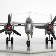
Horten Go.229A (03859) 1:48 Carrera Revell The Horten brothers were a pair of visionary siblings that designed a series of flying wing gliders in pre-WWII during the period when Germany was prohibited from having an air force. Each design improved on the last, and once the Luftwaffe broke cover in their expansionist phase before WWII, development began in earnest. The requirement for a light bomber capable of the 3x1000 by the RLM, which was for an aircraft capable of carrying a 1,000kg bomb load a distance of 1,000km at 1,000kph in 1943 set the wheels in motion that resulted in the Horten.IX, which is better known as the Ho.229, and sometimes referred to as the Go.229 due to the fact that the Gothaer factory had been chosen for production examples. The flying wing had a low drag form, and the addition of two jet engines gave it the potential to fulfil the requirement, although it suffered a little from lateral instability due to its slick shape. The first prototype flew un-powered and with fixed landing gear in 1944, with results that bore plenty of promise before crashing due to a pilot error. Gotha altered the design in practical ways to ease production and increase longevity, as well as adding a rudimentary ejector seat that was probably as much of a danger to the pilot as being shot down and having to bail out. Another prototype was lost due to an engine fire, but this did not deter the RLM from striving to reach production, despite the worsening situation in Europe for Germany. The third prototype was enlarged, and it was this that fell into the hands of the advancing US troops, and subsequently the Operation Paperclip team, who took it back to America with plenty of other advanced designs. It remains there to this day, in the restoration area of the Smithsonian's NASM. The Kit This is a reboxing of Dragon’s excellent rendition of this unusual flying wing design that inspired a number of efforts to create a flying wing design post-war, most of which weren’t unduly successful with a few notable exceptions thanks to the march of technology. The kit was first seen in a Dragon box in 1992, and the moulds are wearing well, although a little flash has crept into the moulding for some of the small parts on my example, but that’s the work of moments to remove. At the time, the kit was fêted for including a cockpit, gun bays and two engines in their compartments, with the option to show them off if you wished. Those aspects of the kits haven’t gone away, so there’s plenty of options to personalise your model from within the box. The kit arrives in an end-opening box with seven sprues of pale grey styrene, a small clear sprue, a sheet of Photo-Etch (PE), decal sheet and the instruction booklet with colour profiles on the rear pages. Construction begins with the cockpit tub, which is moulded into the top deck of what could be called the fuselage. The cockpit sides are decked out with tubular framing, and the small crowded instrument panel with decal fits into the front with the control column. The basic ejection seat has a separate headrest and foot pegs, and the last step of the instructions show the application of seatbelts that you are shown making from paper with PE furniture included on the nickel-plated fret, so they can be fitted without painting. A lot of folks will substitute some Tamiya tape for the paper, as it’s a little less absorbent of paint, and closer to the right colour. Rudder pedals and the gunsight are installed in the front of the cockpit, with a clear part for the glass. Attention shifts then to the twin Junkers Jumo 004B turbojets, the front and rear of which will be immediately familiar to anyone that has built an Me.262. The rear bullet is made up first, with a representation of the aft of the engine visible behind it, then the main casing is made from two parts with a front bullet and the aforementioned rear inserted within on a pair of ledges. Nine additional parts are attached to each engine to depict the ancillaries, and there are detailed painting instructions throughout for anyone wanting to leave the top panels open to show off their hard work. The front of both engines are inserted into the nose cone intake trunking on location pegs, then put to one side while the lower fuselage and gun bays are made up. A pair of chunky MK 108 cannon are included in the box, with ammo feeds glued to the sides before they are laid in the floor of the lower fuselage, to be surrounded by the framework structure of the aircraft, and a representation of the ammo boxes that feed these 30mm beasts that consume ammo at a rate of over 600 rounds per minute each, given the opportunity. A pair of frames are then placed at the wing roots, and the engines with their forward cowling are dropped in place, taking care to align the two parts for a good flush join. The top of the fuselage is brought in and glued into place, with either the engine cowling panels fitted over the top, or with a little more framework added over the engines, you can choose to leave the panels off to showcase your work. The laminated wooden wings had very little in the way of panel lines, which is faithfully depicted here, with the elevons and spoiler flaps moulded in the neutral position. Each wing is two parts, and they attach to the fuselage in much the same way as the real thing, mounted on twin brackets with large pegs (read: bolts) fitting through both parts to hold them in place. You wouldn’t be blamed for adding a little glue to the proceedings to ensure they stay in position however. A pitot probe slots into the leading edge of the port wing, and wingtip light lenses can be found on the clear sprue. To save development costs and time, the tricycle landing gear initially utilised some parts of existing aircraft, with He.177 wheel rims remaining in this version of the airframe’s development. The nose wheel is made from two halves with a balloon tyre, and is attached to the strut by a pair of V-shaped yoke parts on a two-part pivot that also holds a substantial mudguard. The assembly is then linked to its retraction system, with another U-shaped yoke, cross-braces, and surprisingly long links that lead well back into the fuselage. The main gear legs are more straight forward, having a stub axle and moulded-in scissor link, plus the retraction jack that pulls it sideways into the bay. Each one has a captive door on the axle, with two smaller doors attached to the edges of each bay. The nose gear has a large curved front door, and two long side-opening doors covering up the insanely long retraction mechanism. The two cannon barrels with their perforated muzzle-brakes that are well-moulded for the scale are popped in the leading edge of the wing roots, while an antenna, small intakes, clear light and D/F loop are fitted to the underside, and the lower fuselage/engine bay panels are inserted, leaving a small rectangular chute for the disposal of spent brass casings. Finally, the canopy is fitted in two parts, with the shallow windscreen glued to the front lip, while the sliding rear has a T-shaped retainer added, which allows it to be inserted into the track in the rear deck, so that you can open or close the canopy at will. Markings The 229 never saw active service thankfully for the Allies, so the two schemes are speculative at best. From the box you can build one of the following: Blaue/Blue 4, Luftwaffe, 1945 Rote/Red 13, Luftwaffe, 1945 Decals are by Cartograf, which is a guarantee of good registration, sharpness and colour density, with a thin gloss carrier film cut close to the printed areas. Conclusion There’s something impressive about the futuristic look of this 1945 era flying wing, and although it was largely untested as a fighter, it does have an appeal that attracts many modellers, myself included. Whether the laminated wood construction would have held up to extended use is anyone’s guess, but the tooling for this kit certainly has. Highly recommended. Revell model kits are available from all good toy and model retailers. For further information visit or
-
 A model from 5 years ago Here is another Arup flying wing, this time the earlier -and smaller- S-2. There were at least three different configurations and color schemes; here I am reproducing the one without the wheel fairings. I have a great opinion of Bill Hannan and collaborators, my main source of info came via one article on Skyways magazine of January 1997, but I differ on the interpretation of the colors, and tend to believe, in spite of their explanations, that there were possibly three colors involved, red, black and aluminum. Just a personal interpretation, not more valid by any extent than theirs.
- 22 replies
-
- 35
-

-
- Arup S-2
- scratchbuilt
- (and 1 more)
-
An unusual but beautiful golden age "flying wing", a build from 3 years ago. The Golden Age of aviation... long distance or endurance flight records were being often beaten again even before the winning machines and pilots could fully enjoy their glory. Amidst this background that is my usual inspiration field, recently three designs caught my attention; they are similar in some regards but have distinctive characteristics. I am referring to the EMSCO (E.M. Smith and Co.) "flying wing", and the Bryant and Vance "flying wings". None of them is, actually, a real flying wing, but the term points out to the absence of a "real" aft fuselage, being this replaced by the twin-boom arrangement. So we have a fuselage pod, usually short, instead of the traditional fuselage to which all other members attach. These designs relied on refined aerodynamics and large, high-aspect ratio wings, associated with high lift capacities and the ability to carry a large fuel load. None of these three were particularly successful, a fact about which I give a rat's bottom. The Bryant had a push-pull twin engine arrangement. The Vance design was quite similar to the EMSCO, but with double vertical stabilizer instead of the single one. There is a lot to be said about these three machines in general and about the EMSCO in particular, but I will say no more; if you are curious, go find about them, they are very attractive and have juicy histories. You won't regret it, but I won't do it for you, enough work is for me to scratchbuild these belles. Suffice to say about the EMSCO is that it was designed by Charles Rocheville (the same designer of the Rocheville Arctic Tern that I built long ago). The EMSCO had two strange aerodynamic devices: the fuselage pod was a duct inside a duct, to channel the inner airflow from the NACA cowl aft of the engine. There was also another device that ingested air, located beneath the wing, and pumped it through slots on the aft upper airfoil, thus creating what we call now a blown-wing. These devices were to help the lift and speed of the plane. They worked very well, according to contemporary accounts. The model: Every scratchbuilding project is a challenge, for diverse reasons. There are always areas or parts that require some head-scratching, and that's part of the charm of scratchbuilding. In this case there is not even a plan, or a meager 3-view. So I had to work on a plan, or better said, a building sketch. Once the plan was more or less ready, work began on the model, and there a second challenge appeared: the fuselage pod, which was, as said above, a duct inside a duct. The inner duct surrounded the pilot and copilot stations, which were located therefore in a sort of bathtub. The air entered at the front of the NACA cowl, passed through the fuselage main section and then the aft cone which acted like a Venturi device and then the air was expelled at the narrow end. My thanks to Lars Opland and Alain Bourret who provided some additional useful pieces of information. Mika Jernfors came to the rescue with the decals I commissioned from his outfit, Arctic Decals. Enjoy your EMSCO flying wing
- 19 replies
-
- 30
-
-

-
- EMSCO
- Flying wing
- (and 1 more)
-
 Airframe Detail #8 – Horten Ho.IX/Ho.229 ISBN: 9781912932108 Valiant Wings Publishing After WWI Germany was prevented from having much of any form of military, including aircraft. This led to a lot of glider flying in the period before the Nazi regime was ready to ignore the Versailles Treaty openly, and the Horten brothers were master glider builders, having a keen interest in the flying wing format that began a line of designs that improved the gliding experience by removing the drag associated with a traditional fuselage and tail plane assemblies, with the pilot buried within an all-wing structure and control provided by pop-out drag rudders and spoilers. After WWII began the brothers joined up to fight for their country, but when the RLM made a request in 1943 for a new fighter design with jet power, the remaining brother Walter (Wolfram was killed in 1940) began designing what was to become the Ho.229, with two jet engines buried in the leading edge of the wing either side of the cockpit and exhausting over the pointed trailing edge of the wing. Using mainly non-strategic materials and recycled parts for the landing gear (Bf.109 main, and crashed He.177 for nose), it was in prototype stage by the end of 1944, when it flew as a glider. By February of 1945 it was test flown under its own power, a crash later killing one of the test pilots, then when the Gothaer Waggonfabrik (Gotha) factory was overrun by the Allies, the V3 airframe was scooped up by the US forces and taken back to America for study. Due to much neglect over the years the airframe is now in a sorry state of repair, with delaminated surface panels and a great deal of corrosion, plus a rather grim and inauthentic paint scheme that was applied by the Americans for reasons best known to themselves, probably propaganda. This book, by prolific author Richard A Franks, with profiles and plans by Richard J Caruana and example model produced by Libor Jekl is perfect-bound as usual and consists of 66 pages within a card jacket, printed on glossy paper stock throughout. It is number 8 in the Airframe Detail series that concentrates more on the aircraft in question, with just a short section to the rear with an example build of the relatively recent kit in 1:72 from Zoukei-Mura models, which seems to have escaped my notice. The book is broken down into sections as follows: Introduction 1 Technical Description Detailed coverage of construction and equipment 2 Camouflage & Markings Colour side profiles, notes and photographs 3 Small Scale Horten A build of the 1:72 scale Ho.229 kit from the recent combined 1:144 & 1:72 set from Zoukei-Mura by Libor Jekl Appendices i Ho.IX/Ho.229 kits ii Ho.IX/Ho.229 accessory & mask list iii Bibilography Despite there being only one airframe that survived the war in an embarrassing state, there are tons of photographs, diagrams and profiles, many of which are contemporary in black and white due to that being the predominant film format of the day, but with some colour photos from later periods. The profiles are found in the 2nd section of the book, and show a number of what-if schemes of various nations for your consideration. The sheer level of detail giving within the pages is perfect for the modeller, and will be of use to anyone from novice to super-detailer, with some of the photos and drawings showing the interior, subassembly layout, the instrument panel and other fine details that could improve your build, many of which I haven’t seen before. Libor Jekl's build of the new ZM kit shows what can be done to the 1:72 model, and results in a lovely example that anyone would be pleased to have in their collection. From a modelling standpoint there is scope for building and painting one of the other smaller scale such as the 1:144 Brengun, 1:72 ZM or Revell, or in 1:48 ZM or Dragon and ZM's highly detailed kit in 1:32 . Conclusion Another Excellent volume from Valiant, and an interesting one especially for those like myself that are interested in the experimental airframes that the Germans were working on at the close of WWII. Very highly recommended. Review sample courtesy of
 -
A model from 5 years ago, with the original text: To boldly avion where somebody has gone before: Flying wings are a particularly attractive subject among modelers of a certain breed. There were also test beds and midway concepts, like the Junkers G-38 and the Northrop first "flying wing", that were not pure flying wings (had tailbooms and tail surfaces) but a cautious approach to the concept. Although Jack Northrop is erroneously credited by some for having either invented or developed the concept (he did neither), the history of the flying wing stretches far beyond. Interestingly enough, the particular stressed-skin, all-metal flying wing depicted here (the "Northrop" Avion 1) started as a concept pioneered by one of Northrop's associates and later employee, Tony Stadlman. It was him that started Northrop on the thread, although Jack later appropriated his work and even had the face to get mad at Stadlman. Northrop was a great contributor to aviation development on his own right, but the flying wing was not his idea, not even "his" flying wing was his idea. Stadlman was an immigrant from Czechoslovakia that also contributed to the engineering and construction (he was a co-filer of the patent) of Lockheed's monocoque structures. Be this then an homage not to Northrop (by the way, once more, it is not "Northrup" as erroneously and extensively written in many places), but to Stadlman, the original thinker behind this particular concept. On the Net you may find photos of him holding a model of his flying wing, if you see a remarkable similarity between his and Jack's flying wing, it is NOT a coincidence. The Avion went, as many prototypes do, through a number of modifications. The horizontal stabilizer is seen in a few images with a portion outside the vertical stabilizer, more according to patent drawings, but was later trimmed back. Extra portions of surface were added to the vertical stabilizers and ailerons, and also to the stab leading edge, which is seen passing beyond the fins' leading edges; the engine was installed as a pusher (prop behind) and a tractor (prop in front), the taildragger tricycle landing gear started as a retractable unit but very soon adopted the simplicity of a fixed one, and therefore the landing gear legs and struts were changed. The Avion could fly two, but the right position was faired over. Photos show also the minor changes introduced to accommodate the aft or front prop. A windshield can be seen too in some images. Bear all this in mind if you decide to build one, and use photos as references. As it is almost always the case with these oddballs no plans whatsoever or not good ones at any rate could be found, so I modified a plan from the Net using photos and the given measures. The construction techniques are more or less the same ones generally used on the models I posted, although the unusual shape called for a slightly different approach engineering-wise this time. The Avion is a relatively small model in 1/72nd scale. Home-made decals were produced (this time around fortunately only simple registrations) and Aeroclub after-market wheels and prop used. Strange shape, perky stance, shinny surface, historical significance, all make for a nice model if you have the will to go a bit further into the magic lands of scratchbuilding. See you there.
- 28 replies
-
- 36
-
-
-
- Northrop Avion
- Flying Wing
- (and 1 more)
-
 Here is my Anigrand Craftswork 1:144 Horten Ho XVIII B-1 bomber in fictitious Luftwaffe markings since this was one of those many paper projects that never got built. I filled it with weight but in the end it wasn't enough so I had to make a support from clear sprue to keep it from tipping rearwards. The u/c doors were thinned and the guns were replaced by new ones made from metal wire. The kit was fully painted with brush except for the flat varnish which was airbrushed. Thanks for looking Miguel
 -
These are all old builds, and in retrospect should have been posted at the beginning of these series. They often represent the first, hesitant steps on scratchbuilding. Here is another from 2007, 12 years ago (original text as posted then): The flying parable of Boris Ivanovich Cheranovsky. The BIch 7a is the predecessor of the BICh 14: a twin engine transport, also a parabola wing design, being the 7 a bit smaller (could carry just two comrades). Yes, it flew, having some trouble with the engine but otherwise pretty good in performance. Not much came out of it, though. If you think that this was 1932, and also considered the Russian winter, only admiration can be felt. A singular machine that could well have been included by Andrei Tarkovsky in “Solaris” –by the way, the original one-.
- 4 replies
-
- 19
-
-
- Golden era
- Russian
- (and 1 more)
-
These are all old builds, and in retrospect should have been posted at the beginning of these series. They often represent the first, hesitant steps on scratchbuilding. Here is another from 2006, 13 years ago (original text as posted then): Some times Russians don't make just planes. They make flying poetry. Boris Ivanovich Cheranovsky dreamed about the half-moon gliding on the frozen surface of the lake. And he created a series of planes with a charm that is hard to ignore. The daring design created some stability problems, but most of his planes at least flew, and some times they flew very well. I just posted my scratchbuilt BICh 7a, a smaller, previously designed plane, for size and type reference: The BICh 14 was a transport (four passenger) version, and both date from the early 30's. For the construction of the model I used some styrene, wood, metal, invocations, imprecations, a magic wand and some pixie dust. The interior was provided with five seats, control column, instrument panel and rudder bar, all to be forever forgotten under the dark, impenetrable canopy. The Townend rings were made of two layers of .010 styrene wrapped around the right size of metal tube, and later a half-round styrene rod was added as a lip to the inner front side. Once dry the part was sanded close to shape. The engines were made of scored styrene rod and stretched sprue, and the half-round front covers are heat-and-smash styrene over a rounded dowel end.
- 5 replies
-
- 21
-
-
-
- Flying wing
- Russian
- (and 1 more)
-
These are all old builds, and in retrospect should have been posted at the beginning of these series. They often represent the first, hesitant steps on scratchbuilding. Here is another from 2006, 13 years ago (original text as posted then):. Look! it's a spaceship from Saturn!...a flying doughnut!...the last area 51 project!...well, actually not. It is a pioneering plane devised by two gentlemen from Britain a few years ago (more than a hundred, actually) to take advantage of an interesting aerodynamic concept. And yes, it flew...eventually. It was powered by an enclosed 80 hp Gnome engine, could carry two people and had elevons. After a research session in my library and the Net, I found notes and images that helped a lot, but I also found the seemingly unavoidable contradictions among references that I like so much. Anyway, choices were made, a new # 11 blade was inserted in the handle and very much in Monty Python's Holy Grail fashion we went, to travel across the meandering paths of scratchbuilding, clapping our coconuts. As you can see in the images, the usual pre-kit is cut from styrene, a 7 cylinder engine made of the same material and some spare parts adapted for the occasion. Finally, the strange but beautiful shape of the Lee-Richards annular wing will cruise again on the sky of imagination.
- 7 replies
-
- 18
-
-
- Flying wing
- early aviation
- (and 1 more)
-
A build from 11 years ago: The Ford Company involvement in the aviation industry had some bizarre, lesser known sides than its proverbial trimotor. Of this obscure past almost nothing exists now, as if a stealthy hand had erased the trail of some strange ventures. Among those ventures are the Stout Dragonfly (a tandem amphibian design) and the subject of this article: the Ford 15P flying wing. These designs followed the same pattern of the Ford Flivver, aiming to provide an affordable ride to every-day people and in doing so supposedly replicate the success of the Ford automobile. Not many photos exist to document the 15P. There was a mock-up with a faked registration and then the real thing. The lines were very attractive; the engine was behind the two-seat side-by-side cockpit and transmitted power to the tractor propeller via a shaft. And in case you are asking yourself yes, the engine was indeed a Ford V-8 engine. For 1932 the design does really look futuristic, with those curvaceous, trousered landing gear legs and the tear-drop blended fuselage. The 15P flew quietly into oblivion, though. The model consists basically of one upper and one lower vacformed shells with the addition of wrap-around style styrene sheet wings. A succinct interior was provided and a few external details added. The gear legs, given its complex curvatures, provoked a bit of head-scratching during the construction process. The issue was finally solved using several pieces of styrene to determine the general shapes and then “rounding” with Milliput. MV Products lenses were used as landing lights. The originals look a lot like car headlights. Finally, the chubby although somehow racy shape of the 15P came to light and surely Humpty-Dumpty would not have been uncomfortable flying this plane and, like the character, it just makes you smile, doesn’t it? -I would like to thank Mike Fletcher and (the late) Jim Schubert for their help with this project.
- 18 replies
-
- 23
-
-
- Ford 15P
- flying wing
- (and 1 more)
-
A model from 12 years ago: Specially conceived to fly to the Boulangerie, get the highest possible number of baguettes and croissants and get back on time for breakfast with minimum fuss. A collaborative venture between Nicolas Roland Payen and Aubrun originated this cute little French plane that was propelled by a 25 hp AVA engine. It flew in 1935 and 1936 receiving later a 40 hp engine which modified a tad the nose profile. At 4.95 meters of wingspan this tiny plane was a consistent flyer of which a derivative, two-place version was conceived but ultimately not produced. Quite a sight it must have been with those curvaceous, moth-like elegant lines and the purr of the small power plant. At a little bit less than 7 centimeters (2.75 inches) span, it's tiny.
- 4 replies
-
- 16
-
-
- Aubrun-Payen AP 10
- Flying Wing
- (and 1 more)
-
A build from 11 years ago: In the continuous quest to explore the boundaries of design several individuals came up with strange but efficient solutions that in some cases were years ahead of conventional thinking. Romanian designer Filip Mihail had some advanced, farsighted ideas. He was unfortunately ignored by the retrograde, shortsighted authorities of the time. His concepts were developed with the little help he could receive and came to full fruition in 1933, when the Stabiloplan IV was successfully flown. The flying wing-cum-kiddie car performed extremely well, so well that was ignored, as it is some times the case with good things. It is of note the fore-aft movement of the wing quoted by sources in order to obtain pitch control. I couldn’t resist the urge of building this little gem from the Golden Age, but faced a common challenge in dealing with this kind of subjects: lack of sufficient information. Still pending is a confirmed color for the flying surfaces, which appear somewhat dark in the available photos. A sort of calico color was used in the model but the above-mentioned surfaces were attached with just a very small dab of white glue, in order to be removed easily if a confirmed color pops-up in the future. The fuselage is showing a varnished wood finish in the images, which was achieved using an acrylic orange base and crimson red and a smidgeon of black oil paint applied in streaks with a flat brush in a medium consistency. Some interior was built to spice up the bathtub-like fuselage. Aeroclub Models wheels were used to match the originals and the rest is the usual liberal use of styrene raw material and bits of metal here and there. Together with the recently posted Henri Mignet’s Pou-du-ciel and other pocket-size design on the cases they make a group that is funnily dwarfed by contemporary cousins of normal mass. I just can’t but love its cartoon-like appearance.
- 12 replies
-
- 22
-
-
- Stabiloplan
- flying wing
- (and 1 more)
-
A build from 11 years ago: We are talking arcane here. Like a strange moth, or flying ravioli, or piloted manta-ray, or perhaps a motorized cookie, the Canova flying wing glides across the sky. Or does it? Little can be found on this one. A “Flight” magazine article states that Mr. Canova’s all-wing design has been tested in wind tunnels at Milan and Rome and that no less than 5 scales models were built. This model is based on the project figures given in the article. At least one full scale machine was built. Nihil novum sub sole, as they say. When we see the “new” designs that populate the skies nowadays, it is interesting to compare and see how really new they are. Time and time again, neglected, laughed-at strange concepts of earlier periods are re-hashed and re-presented as cutting edge. Makes you wonder about the things that are laughed-at today and will be state-of-the-art tomorrow. Minute cute little model in 1/72, not really complicated to scratch, guaranteed to raise many an eyebrow. Styrene sheets of diverse thicknesses were used and Aeroclub Models wheels, engine and prop completed the model. A disfruttare! https://www.flightglobal.com/pdfarchive/view/1935/1935 - 0956.html
- 8 replies
-
- 24
-
-
- Canova
- Flying wing
- (and 1 more)
-
A model from 12 years ago: (A rather coarse and basic effort now that I see it 12 years later, but it was one the first scratch projects; in any case I thought that in spite of the shortcomings of the model you may enjoy the strange design of the real plane): To say that the Johnson’s Uni-plane of 1934 was once offered by his builder to a hamburger company to make flying advertisement will completely make the case. The builder, though, couldn’t: due to an unfortunate crash upon take off -one in a series of them, if I may add- sponsorship was unplugged. At a mere 14 feet span (about 4.27 meters) massive it is not, but radiates charm. A Church Marathon of 42 hp took the plane to the air, but since in its first incarnation it had only control in two axis (no ailerons), it was extremely difficult to make it stay there. Further development included a single vertical tail and the missing ailerons, but this lovely machine stubbornly refused to stay aloft. It made, though, a series of straight-line long hops and eventually –err, after some crashes- reached plane’s heaven, wherever that may be. Oh, behold the strange shape of the Uni-plane! Any resemblance with the “Voyager” of “Star Trek” or the nose of the “Seaview” from “Voyage to the bottom of the sea” is a mere coincidence. The (not-to-be) flying hamburger is another proud member of a long lineage of airborne food items like the Lee-Richards annular wing –AKA flying doughnut-, Charles Zimmerman’s “flying pancakes”, B. I. Cheranovsky’s “flying croissants” and so forth. With this one, the expression “piece o’cake” reaches new heights (although "heights" here is a strictly poetic term). Enjoy! http://eaavintage.org/october-2015-mystery/
- 8 replies
-
- 20
-
-
- Johnson Uniplane
- flying wing
- (and 1 more)
-
A build from 9 years ago: The use of radial engines in small airframes tends to create very cartoon-like shapes of an undeniable appeal. Some of these stumpy, chubby, cute little bugs are well known (like the Gee-Bee racers or the Polikarpov I-15) while others are more obscure subjects. If this type of design was a monoplane (like the Bristol Type 72 Racer or the Polikarpov I-16), then the effect was even more notorious; but if on top of that we have a “flying wing” example, then the resulting aesthetics are just as fun as they are attractive. The BOK-5 was a Russian design proposal originated –as the designation states- at the Bureau of Experimental Aircraft (Buro Osovikh Konstruktsii) and the project was led by V. A. Chizhevsky. It had a Mikulin M-11 as its power plant and a span of less than 10 meters. It had metal structure and the flying surfaces were mostly fabric-covered. After initial flights and some adjustments the plane revealed itself as a very good machine, but notwithstanding its virtues didn’t go into production. The Scupley-made fuselage master fitted comfortably in the Mattel Vac-U-Form plate and promptly I had my two fuselage half-shells. The interior was furnished according to references and then the wing was fabricated out of styrene sheet and rod as per photos. A sort of Townend ring was created laminating styrene sheet on a metal tube–see also the images to follow the simple procedure- and an “Engine ‘n Things” Mikulin was retrieved from deep hibernation in the spares bin. This particular engine is not the best one I have seen from this manufacturer, being the back side well detailed and the front side marred by the area of the cylinders enclosed by the pushrods, which was a pool of resin. Some pinholes –or potholes- further enhanced the overall results. Wing and fuselage were mated, but no eggs were laid. Details on the fuselage were added and then the under-hanging control surfaces for the wing. Wheels came from Aeroclub and landing gear structure was a combination of assorted bits. Last details were the home-made wooden prop and a number (14) of photoetched control horns, which amused my ears with the “ping” sound they made every time they jumped to hyperspace from the tweezers. Finishing presented a dilemma. The original color was apparently either white or light grey, but I think that aluminum is a possibility as well. Some color reported as red –which will make sense being this a Russian plane- was applied to the nose ring, leading edges and to some trim lines on the upper fuselage. But for the annual parade a very original and psychedelic scheme was applied, a la Kalinin K-12 “Zhar Ptitsa”. This artistic scheme is represented in different ways by several sources. The usual heavily retouched Russian photos duplicated with hectographic gelatin in the cold basement of a Buro (http://en.wikipedia.org/wiki/Hectograph) did not help. That made me lean towards the original scheme. Few decals for this one: only the concentric circles for the wheels and the BOK triangular logo for the rudder
- 12 replies
-
- 24
-
-
- BOK-5
- scratchbuilt
- (and 1 more)
-
A build from 5 years ago Another iteration of the Arup. The Arup family of planes had the goal of providing an economical, reliable, low speed machine that was easy to fly and simple to build and maintain. During the thirties there were a number of attempts by different countries to achieve that elusive goal. These series of flying wings (I just posted another two) is well known to the enthusiasts, but even general aviation buffs sometimes never heard of them. The model presented here is a nose tricycle modification of the S.4 model, powered by a 70hp LeBlonde engine and a span of 22 feet. Access was via a hatch that opened partially bellow the left wing and partially on the fuselage side. It could carry two people with dual controls and had the registration 14529. There is plenty on the Internet about the Arup wings, so if you feel curious use your fingers and look it up.
- 3 replies
-
- 16
-
-
- Arup S-4 trike
- scratchbuilt
- (and 1 more)
-
A build from 2 years ago: This Arup, which has a tailwheel besides its front tricycle landing gear, is mostly seen in photos tail-sitting, thus no lead was added to the nose. The pilot's weight made it "seat right".
- 2 replies
-
- 13
-
-
- Arup S-4
- Flying Wing
- (and 1 more)
-
Flying wings are supposed to be ultimate flying machines. But for different reasons there are very few examples of successful flying wing designs. Most of aviation enthusiasts know about mighty XB-35, but have you ever heard of DB-LK - Soviet pre-WW2 attempt to build a long range bomber based on flying wing concept. ДБ-ЛК stays for "Long Range Bomber - Flying Wing", the plane was designed by Victor Belyayev and remains one of the oddest aircrafts ever flew. AMT/ERTL XB-35 kit is well known, DB-LK replica in 1:72 is represented by resin kit from AirKits http://modellingworkbench.blogspot.co.uk/2010/09/db-lk-172-resin-kit-review-kajukair.html The photo of completed model by made by kit manufacturer himself Okay - let's get started. The boxes Airbrushed parts with Mr. Resin Surfacer Mounting rear turret assembly Fuselage parts glued together - had to remove a lot of resin from the side walls and do some scratch building In a mean time - assembled and painted XB-35s cockpit Joinned it with ..... a wing ?.... The canopy has developed an incurable crack when I removed if from the sprue so I decided to "push" a new one from acetate film Filled the original canopy with epoxy for strength and mounted a piece of film is attached to a piece of cardboard whith a hole that matches the canopy and heat over portable electric cooker (no open flame) once the film is hot and soft it is gently "pushed" over the mounted canopy "master" I made about 10 copies and chose the best The result Usually I use Mr.Surfacer as a primer, this time I decided to prime with Halford's Alluminium that I poured out of spay can and apply with conventional airbrush to reveal scratch marks Well well - American approach in visibly different from Russian
- 69 replies
-
- 13
-
-
- Flying Wing
- XB-35
- (and 1 more)
-
This turned up Tuesday and it must be started, it says. I won't be using the kit's decals but building it as the prototype but unfortunately there are no swastikas. I have done a little research. If you can tell me where to obtain some swastikas from I would be grateful. Box art. Decals. Bits and bobs. Some PE. Thanks for stopping by and having a look. Stephen
- 6 replies
-
- 5
-
-
- flying wing
- ho 229
- (and 1 more)
-
1/72 Revell Arado AR (E) 555-I, I/KG 100, 6N-EK, Luft '46. Here is the fantastic Revell offering of an incredible design by Arado. This was an initiative of the Reichsluftfahrtministerium (Reich Air Ministry), RLM, to obtain a long-range bomber for the Luftwaffe, that would be capable of striking the continental United States from Germany. The first time I saw this kit I knew I had to build it one day. At one stage I had an extensive collection of exotic German aircraft and this kit would of joined them. My collection has been dramatically reduced now so this actually falls out of my collection theme. It still needed finishing though and I am very pleased with how it has turned out. Airbrushed using Vallejo paints, weathered with Flory dark wash and sealed with matte varnish. You don't generally see many of these built up and it was an absolute joy to build. I hope that you enjoy the photos. Cheers guys, Phil
-
I'm usually a firm Cold War man (with a fair bit of modern), but recently I've been getting rather interested in the last days of the Reich and the aircraft that they were producing: I love the idea that while these apocalyptic battles were going on closer and closer to Berlin, Nazi scientists worked feverishly using untapped technologies to create devastating new superweapons to unleash on the allies...well, you get the idea! So I ended up buying the 1/72 kit of an aircraft that's actually been thrown into the limelight recently with the Zoukei-Mura 1/32 kit. It's been in my stash for a couple of months now but with halloween approaching, I thought that it would be a good time to build this undoubtedly sinister looking aircraft. Lovely box art showing the Go229 in action: Nicely detailed fuselage: Cockpit parts in place and given a quick blast of rattlecan Humbrol Dark Sea Grey Wings clamped and drying: Instrument panel painted and decaled: Seat basecoated in Tamiya XF-61 Dark Grey, painted in Vallejo Model Air American Blue, harness straps and headrest done in XF-60 Dark Yellow, buckles done in XF-56 Metallic Grey, then the whole thing washed in Citadel Devlan Mud Off camera, I also gave the cockpit area a wash and did the rails and picked out the details in Metallic Grey Until next time!
-
Horton Ho.229 1:32 Zoukei-Mura The Horten brothers were a pair of visionary siblings that designed a series of flying wing gliders in pre-WWII during the period when Germany was prohibited from having an air force. Each design improved on the last, and once the Luftwaffe broke cover in the expansionist phase before WWII, development began in earnest. The requirement for a light bomber capable of the 3x1000 by the RLM, which was for an aircraft capable of carrying 1,000kg 1,000km at 1,000kph in 1943 set the wheels in motion that resulted in the Horten.IX, which is better known as the Ho.229, and sometimes referred to as the Go.229 due to the fact that the Gothaer factory had been chosen for production examples. The flying wing had a low drag form, and the addition of two jet engines gave it the potential to fulfil the requirement, although it suffered a little from lateral instability due to its shape. The first prototype flew un-powered and with fixed landing gear in 1944, with results that bore plenty of promise before crashing due to a pilot error. Gotha altered the design in practical ways to ease production and increase longevity, as well as adding an ejector seat that was probably as much of a danger to the pilot as being shot down. Another prototype was lost due to an engine fire, but this did not deter the RLM from striving to reach production, despite the worsening situation for Germany in Europe. The third prototype was enlarged, and it was this that fell into the hands of the advancing US troops, and subsequently the Operation Paperclip boys, who took it back to America with plenty of other advanced designs. It remains there to this day, in the restoration area of the Smithsonian's NASM, and you can see some stunning photos and interesting text on their mini-site here. The Kit By heck, but there's been some hype about this kit, and a lot of people queued patiently at the recent SMW to receive the first batch that was available to the public. Thanks to the patience of one of our review team we have one on hand, and it is an amazing example of injection moulding technology that borders on art! With typical ZM style, the kit arrives in sleek box in the "house style" that fits in nicely with their other offerings such as the He.219 (another beautiful kit!). On the cover is a CGI rendering of a 229 shooting down a Lancaster, and in all honesty, it's not the most realistic or detailed painting, but is perfectly adequate for the job. No effort has been spared on the inside of the box though, which has an inner fold-back lid and a card divider within to help keep everything where it should be. If you've been following the buzz about this kit you'll already know that there is a substantial amount of clear plastic in the box, as the model is designed to be able to built with semi-transparent skin that shows the detail packed in underneath. Of course, you can always paint over that, and many of us will, but the option is there. There are seven sprues in clear styrene, and another twelve in grey styrene. There is another small sprue that was loose in my bag for the landing gear covers, but your box should have this inside. You should also note that ZM have noticed a mistake in the numbering of sprue R, which you can find out about here. All you need to do is re-number the parts on the sprues and everything will be ok. The package is rounded off with a set of canopy masks in a green material, a relatively large decal sheet, and of course the instruction booklet. If you haven't yet had the pleasure of perusing one of ZM's kits, the instruction booklet is a very handsome affair, with 3D drawings of the parts and plenty of accompanying hints, tips and explanations of what you're building. It is broken down into several episodes, and there are pictures of the completed article interspersed with the instructions, so you can compare your work against theirs. Whoever built the example kit did a lovely job of it, so we have a high standard to live up to! You can of course treat yourself to some of the extras that are available from ZM, which includes pilot figures, ground crew, metal landing gear, resin wheels, brass barrels and an additional PE set to improve the detail still more! There is also a forthcoming conversion set that will let you build a two-seater, a set of Vallejo colours specifically formulated for the kit, plus a Concept Note book that should help with the build. Construction begins unusually with the two Jumo 004 engines, which have a full suite of eight compressor blades along the central shaft just like the real thing, which is trapped between the forward engine housing after adding the half-moon static blades within the shell first. Each pair is different, so much be installed in strict order, and care will be absolutely imperative if you hope to install the turbine shaft, as the cut-outs in the static blades match the shape of the hubs. The intake bullet is a two-part assembly with the front compressor face added to the rear, which is then trapped between a pair of cowling parts split vertically, plus another pair split horizontally in front of those, forming the inner intake lip. The exhaust has two final phase rotors attached to a spacer, which is in turn glued to a set of stator blades, and finally the rear bullet is put in place. The engine shell is then completed by adding a ring to the back of the compressor phase, linking the exhaust assembly to the rear of the turbine shaft, and lastly enclosing the shaft and part of the exhaust assembly in more cowling that joins horizontally. The outer casing can then be painted up as per the photo instructions. A lot of ancillary equipment comes with a jet engine, and ZM have not skimped on parts here. There are a heap of parts utilised in completing the engine, and painting call-outs accompany them throughout. The final part of the first act is to add the lower heat shields to the aft portion of the engine, which prevented the heat from damaging the relatively delicate wooden skin. These are provided in crystal clear styrene, so that your work with the engines can be seen from the gear bays. As an option, you can cut some square sectioned parts from the sprue runners, and build them up into a trestle for one or both engines either to display them away from the aircraft, or to keep them safe while you finish off the build. Quite a clever use of the otherwise wasted plastic of a sprue! Act two sees the building of the fuselage, which comprises a tubular framework that is very well depicted. The lower frame is built up first to act as the base on which the rest of the fuselage is built, and again you should paint this up as you go, due to the complexity of the finished article. The wing root formers are added to the extreme left & right of the fuselage frame, at which point it starts to look a bit like a Ho.229 for the first time. Various linkages and controls are added, reaching the forward fuselage to be integrated with the cockpit, which is built up later. The cannons and their ammunition feeds are added inboard of the wing joint, after which the engines are added into the lower fuselage assembly and held in place by the addition of the upper framework, so again – keep painting as you go along, or you'll regret it. Fitting this part properly is crucial, and takes up two pages of the instructions, showing where it should locate a number of times from different angles. Another page is devoted to showing the finished article in picture form, which should give you the feeling that if you screw it up, you will have trouble fitting the outer skin, so take care, test-fit and do it right the first time. The third act deals with the cockpit, the framework for which is painted RLM66, although the instructions suggest black, while the photos and general RLM practice says otherwise. The side frames are added first, which makes you realise just how close to the pilot the engines are, and how deaf he would probably get. The pilot's instrument panel is supplied as either a one-piece grey styrene, or a clear part, giving you the choice of how to achieve your desired effect. The styrene part is simply painted up and the supplied individual instrument decals added or the full panel decal, with a dot of gloss varnish added after to give the illusion of glass fronts. The clear part needs to be masked to retain the clear instrument faces, painted and then the decals are placed behind the panel with the use of either decal softening solutions as per the instructions, or a small quantity of clear acrylic varnish to improve adhesion of the wrong side of the decals to the clear plastic. Either should do the job, and a coat of white laid over the back of the panel, then a covering coat of grey/black will hide them from view. The panel is attached to the fuselage via a series of tubular frames, after which you install the control column, with the control linkages below the cockpit floor attaching to the bottom of the stick and latching onto pegs in the outer fuselage area. The ejector seat is made up later, and consists of only four parts due to the simplicity of its design, but it looks good nonetheless. You can use alternative seat bucket parts with moulded in belts, or a blank part if you are using aftermarket belts or installing a pilot figure. Other than the forward roll-over bar within the windscreen area and a piece of nose armour, that's all the creature comforts the pilot had, sitting exposed at the front of the flying wing, and deafened by the sound of his own engines. After the fixed landing gear of the first prototype was lost along with the airframe, retractable gear was installed in subsequent prototypes, with a huge balloon tyre at the front, and two more reasonably sized main gear legs toward the rear. These are the subject of section 4, and it begins with the build-up of the main gear legs, which have a one-piece main leg, separate oleo-scissor links, separate hubs, and two part tyres that have manufacturers' details and spec in raised lettering on the sidewalls. They install into sockets in the underside of the fuselage framework, and are joined with two retraction linkages, and brake hoses moulded in styrene, the location of which is noted in two scrap drawings to the side. The big nose gear leg is moulded in two halves, separated vertically, and its yoke surrounds the two-part tyre with separate hubs, with the mudguard and bracing hoop added after the wheel is installed. The substantial top of the leg is inserted into a large receiver in the nose, and a three-part retraction mechanism is added to the rear. This is also well documented with various views in scrap diagrams around the main construction stage. A final page shows everything installed and painted, then shows the correct angles for the assemblies once they are mated together. Measuring those angles yourself might be a bit tricky unless you hold your model up to the drawing and measure by eye. Act 5 sees the fuselage covered in those translucent outer panels that we mentioned earlier. You will need to make a decision of what to do about them around this stage, and choose whether to model it with a "ghost" skin, partially paint it, or go the whole hog and paint it completely. Of course, you could also go insane and depict your 229 unpainted using some of HGW's excellent wood effect decals. I'm finding that last option quite tempting as I write this, but I'm not paying for any therapy you might need if you go down that route! The first part of the fuselage to go in is an armoured panel that protects the pilot from frontal attacks, which sits inside the nose cone. The nose part itself is a work of styrene art, having been slide-moulded as one piece that incorporates the nose, engine intakes, forward cockpit sills and the outer fuselage leading edge. The lower fuselage skin is made up of three main parts, which fit onto attachment points moulded into the bottom of the fuselage framework, so care and careful gluing is the order of the day, especially if you are leaving any of the panels unpainted. The airbrakes and their actuating rams that cause them to slide out into the slipstream are added before the upper fuselage is closed up, and if you plan to depict them closed, you just nip off the jacks and clean up the stub, installing them flush with the outer skin. The upper fuselage is next, and this comprises a single large upper piece and separate crystal clear engine cowlings, to allow you to show off one or both of your engines. The metal jetwash panels are moulded in, and these are painted bare metal whenever you see fit, and would benefit from a bit of heat discolouration along the way. That's it – the fuselage is complete, but now you need wings. Section 6 deals with the wings, and by now you will know that ZM prefer to give you a distinctly engineering-style experience that involves building a simplified replica of the whole internals of the aircraft. As usual with the wings, there is a simplified version of the wooden internal structure in the shape of ribs and stringers that give the wing stiffness and allow the suspension of ancillary equipment within the framework. The main part is a single moulding, to which is added a more detailed inner end-profile. A set of four fuel tanks are added into the mid and leading edge of the inner two-thirds of the wing, and a single piece depicting the actuating mechanism for the outer flying surfaces. At this point you'd be forgiven for thinking that you should add the skin to the wing, but instead you attach the wing to the fuselage using a quartet of pegs for each one, each of which is attached to a small square of outer-skin. A couple of small parts glue directly to the lower wing skin before it is added, and then you fit the top wing, encasing the innards forever. All the control surfaces are poseable, with elevons along the trailing edge, the inner sections of which also act as flaps. On the top and bottom surface of the wing tips are the drag rudders, a set of paired spoilers than allow lateral direction change. Each one plugs into a slot in the underside of the wing skin, and can be posed closed by cutting off the actuators and gluing them flush with the outer skin. A number of scrap diagrams are there to help you get them sitting correctly, as well as a couple of photos of the finished article in the deployed position. The final phase involves adding all the small parts to the completed airframe. A pair of huge bay doors for the nose gear, two smaller captive doors each for the main gear plus tiny centrally mounted inner doors, and doors in the pen-nib tail for the drag-chute, all of which are best added after main painting is done. The Morane IFF antenna hangs down beneath the fuselage, slightly offset to port, and a DF loop is added to the rear spine, with pitot on the port wingtip. The 229's windscreen is extremely complex in shape, with compound curves on almost every surface, which appear to have been done well. It fits directly to the sill, and locates on a pair of pins in the roll-over bar, but be sure to install the one-piece gun-sight before you put it in place, as it will be a lot more difficult if you don't. The sliding canopy section has been well designed, and you are given two options for the outer skin. You can use the single piece clear canopy, or use a front clear section with a crystal clear aft section that has a central frame projecting from the front that fits along the top of the clear part in a slight recess. Either option then fits to a sub-frame to which the sliding mechanism is added on a cross-member – don't forget that there is a set of canopy masks to aid you with painting. The ejection seat and canopy are then added to the model without glue, the former sliding into place on two ejection rails. The canopy should be able to slide back and forth on its own rails too, giving you the option of open or closed canopy on a whim. Adding the gun barrel stubs to the holes in the leading edges of the wings outboard of the intakes and the clear wingtip lights means an end to construction. Markings There are two fanciful schemes included on the decal sheet, both based on the most likely A-0 series of airframes that were closest to reality. Both are in an RLM81/82 wavy camo scheme, with RLM76 on the undersides, differing only in their tail bands. Example A has a yellow/red band, while B has a blue/green chequer pattern. Anything other than the prototype schemes are mere speculation though, so the world is your oyster when it comes to markings choices. Note that there are no white outline swastika decals included, a pair of which can still be seen on the original airframe, but there are a pair of black ones split in half, to avoid issues when shipping the kits to Germany and other countries where the symbol is either banned or actively discouraged. The decals are well printed with good register, sharpness and colour density, although the instrument decals are a little dark with the needle and calibration details over-powered by the black, which may result in a rather drab panel. As well as the individual instrument decals, there is also a single decal with a full panel printed on it, so the modeller can apply it to the styrene panel and get it settled down with some decal solution. A few oblongs of yellow, blue and green are included for patching in of the tail bands if necessary, although there isn't any red supplied for example A. There are full sets of digits from 0 to 9 with two rows of white, yellow and red, and sections of the latter could be used to patch any gaps in the red tail bands if necessary. Masking and painting the bands is always an option though, as you have the decals to use as patterns for your masks. Conclusion This is another beautiful kit from Zoukei-Mura that just oozes quality from every part. Real care and attention has been lavished on the design of the kit, and the instruction booklet not only holds your hand through the build process, but also imparts quite a bit of knowledge during the process. I like to know what the name and function of the parts I'm gluing together are, and the instructions are more than happy to oblige. The instructions are almost unique (so far) in guiding you through the build as you would approach it from a modeller's perspective, which of course is their target market – these are not pocket-money kits by any stretch of the imagination. Superb in every way – I struggle to find suitable words to recommend it highly enough without sounding sycophantic. It is the dictionary definition of awesome before it became diluted by overuse. Buy at least one right now. Scratch that – get two, and put your name on the two-seat conversion set that's coming soon. Review sample courtesy of
-
W.I.P. thread: http://www.britmodeller.com/forums/index.php?/topic/234955041-two-flying-wings-xb-35-and-db-lk-172/