Search the Community
Showing results for tags 'Scratchbuild'.
-
 This is the model i built a few years ago. Some of you have seen this, watching my Remora build thread. Construction was a series of failures. Initially i wanted to build a 1:12 hover bike but I didn't manage to create a rider figure. So i changed the plan and finished it as a 1:35 scale sci-fi fighter. Then everything went wrong while painting: the paint layer was terribly grainy. I decided that only heavy weathering can save it. This way a clean star fighter became a planetary fighter (from a planet with a very harsh climate) 🤣
 -
This is a first for me, a scratchbuild, so let me tell you the reason why. The intention is to build a Japanese Steamer, the Fushimi Maru and that will be a scratchbuild. So before I start on that build, I thought I better 'cut my teeth' on something less demanding, like a tug: to learn some new skills. The deck plan, side profile and the build process of the subject was acquired via @ShipbuilderMN but this is in wood, I don't do wood, so plastic is going to be used. A quick search of 'tug line drawing' revealed these free plans: Although these are not of SA Everard, they are of a very similar tug and good enough for this exercise of boat building. The plans were scaled so as I can use a standard size sheet of plasticard and copies printed. It's going to be waterline, so we have a 'waterline' base cut to shape, marked with the frame locations and a spine fitted. A few frames fitted. Comments welcome Stuart
-
Just finished this 1/48 scratchbuild. A bit unusual - but adds to the extensive cropduster theme I have had going for a couple of decades. Very long wingspan (55ft = 77m) and a biplane which first flew in 1977. 95 examples built 1979-1983. Have modelled it as an Australian operated example. Build thread over in 'work in progress' (not sure how to insert a link)
- 18 replies
-
- 37
-

-
- Scratchbuild
- Cropduster
- (and 1 more)
-
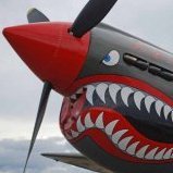
 A recent release from Airfix in 1/48 is the Hawker Sea Fury - one release of which features on the box art the little known (now better known) incident of a civilian Auster (VH-AET) being shot down in Australia in 1955. The story is told on the Sea Fury instructions and plenty of coverage of it online with a bit of Googling. So no doubt plenty of Airfix Sea Furies being built in that scheme - but what of the hapless Auster? Perhaps prophetically, my model club (Australian Plastic Modellers Association - APMA had published an article in 2014 covering some of the history and details of kits/conversion prospects in 1/72 and 1/48. Clearly an accompanying model of the Auster is called for. But there's slim pickings in 1/48 - the Sword kit of the Auster Mk.III is more suited to military use - and the civilian Austers J4 Archer (ie VH AET) has a very different glasshouse and canopy arrangements. So much so that you'd end up scratchbuilding most of the fuselage anyway. No doubt other differences - but rather than do things that way - I thought I'd just scratchbuild the whole thing. I see @Heather Kay did a J1 Auster conversion in 1/72 in 2020 which was a good read! As is always the case, I ended up finding quite a few variants of plans - and finally settled on something workable. And also managed to do my own walkaround of a Auster J/5B Autocar on display at the Queensland Aviation Museum (QAM) - that's a 4 seater vs the J4 a 2 seater so plenty of differences. Starting point was the wings - and I've jumped ahead a bit - but below is a shot of the laminated wings - which had just come out of traction (bulldog clips in the background) and had a bit of sand and clean up... Then onto the fuselage - the rear section of which I elected to make of a box section construction. The fuse sides have distinct lines from the stringers - which I imitated by firstly scoring styrene sheet from the inside - then embossing with a blunt kitchen knife. Pretty happy with the result as you can see in the picture. and on we go with now the fabric 'skin' applied and the basic shape of the front fuselage taking shape. The bulkhead at the front of the rear fuse section will be removed later - it's lightly tacked into to help get the shape right... And here's the wing rib strips being applied using thin tape (and a template modified from the drawings to assist with getting things tight and parallel). I wasn't inspired to use the embossing technique on the wing to better emphasise the ribs - which would have been more accurate but didn't suit my construction technique. So with a little more work we find ourselves with most of a fuselage and the wings - starting to look a bit Auster-ish More to come imminently...
- 27 replies
-
- 17
-
-
- Scratchbuild
- Auster
- (and 1 more)
-
Time for another project. One of my themes is modelling cropdusters in 1/48 - I have completed about 30 most of them scratchbuilt. This one caught my eye a little while back - it's a US designed cropdusting biplane, the Eagle DW.1, which first flew in 1977. That's correct 1977, who'd have thought. A distinctive feature is the incredibly long wings (55ft, 16.8m) with a very narrow wing chord and almost glider like in appearance. Some clever design trickery was used to improve the roll rate. Initially engined with a radial, it is more commonly found with a 300hp Lycoming flat six which in my view makes for a prettier aircraft and will be the subject of my model. Gross weight is 2450kg and a load of ~1250kg could be carried. 95 examples were built between 1979 and 1983 - including a couple that came to Australia (that will be the scheme I model). The picture of the a/c below is shared from user "G.Verver" on Flickr in a banner towing role. So, onto the project. I actually started this in July 2021, and have taken a few photos along the way. The pace is going to pick up a bit from here as I have finished some recent projects. First up I had to refine some pretty rudimentary plans (which I think were enlarged from a Janes of the era). I've drawn these up in CAD including deciphering of the all important cross sections. The fuselage aft of the engine is basically box section to about halfway up - then a compound curved deck over that, with the canopy perched on top of all that. The box section part of the fuse is straightforward enough - just some cut to size styrene (carefully!) and some bulkheads at strategic points. A little forward planning required to make sure I had room for the cockpit later on. The top deck was going to be vacuformed for which I need to make a master. This begins with creating a skeleton - styrene base, main spine, cross sections 'ribs' added (slightly undersized to allow for thickness of plastic to be moulded). The skeleton doesn't need to be pretty - little chunks of plastic offcuts here and there to support the ribs The wing(s) were next on the agenda. Wings are very long, constant section - apart from a tapering of the chord and thickness towards the wing tip. The upper skin, and lower skin are each cut to size from 0.75mm (30thou) styrene sheet. Cut skins about 1mm oversize at the leading edge. (allows room for a bit of skin curvature over the wing, [it's easier to sand back vs fill gaps...]} Trailing edges sanded on INNER surfaces to a knife edge taper. Don't skimp on the knife edging... Main spar from a strip of styrene (40thou in this case) and very lightly tacked into position (if I glue it 'properly' I'll get deformation in the wing curvature when top and bottom are joined). Leading edge (not show here) from 20thou styrene strip. I've elected to leave the entire trailing edge dead straight - and insert the wing tip tape later on by doing a 'cut and shut' - ie crank that part of the wing forward to preserve the trailing edge, and fill/sand etc) Next steps will be: Glue and clamp the trailing edge first (not too much glue, and not too heavy on the clamps. Leave 24 hours. Then glue and clamp leading edge. NO glue on the main spar (again, to avoid skin deformation). A bit more heavy handed on the leading edge glue as there'll be a bit more stress to overcome. Leave 24 hours. Clamps off. And a wet sand with course wet and dry to get correct wing profile. From there - shift to finer grade wet and dry, and a bit of Milliput if required). Also in this pic you can see the progress on the master for vacforming the turtle deck - early days just the one coat of car bog at this point... Here we see the wings now joined up but pre-sanding down. Tips yet to be 'cranked'. And the master for vacforming the top deck visible in the foreground. It took about 3 coats of car bog to get to this stage from the earlier version above. Here we see the vacformed and cut to size fuselage top. I will cut out the cockpit opening after gluing. Leaving it intact ensures I don't get unwanted warpage/distortion when I glue. On the box section of the fuse - I have glued thin 'alignment strips' which will apart from helping with alignment will also give a bit more meat for the glue to bite into (ie far preferable to a butt joint for this sort of application. The basics of the cockpit interior have been added - the floor and formers for the seat bulkhead and seat base. With a quick squirt of black while I'm there. Detail will be added later once the cockpit opening is opened out (quite large) - it's pretty spartan inside... and here we have the fuselage top and bottom joined and held with some builders tape. It doesn't look like much at this stage but confident it'll scrub up. Also the wings are now sanded. The tips have now been 'cranked' - a cut and shut by removing a thin wedge of plastic, inserting a short spar to provide a) alignment and b) strength then glueing. I've given it one coat of Milliput - but have now gone for the Mr.Surfacer 500 to get rid of any remnants of the join. Note the wings are built slightly overlength - which will be remedied when I insert the dihedral and/or the fuselage in the middle! The black cutting matt underneath if 30cm wide (an A4 sheet) which give you an idea of the wingspan Next steps will be clean up fuse, make the fin and tailplane, make masters for the engine cowl and canopy etc etc....
- 57 replies
-
- 14
-
-
- Eagle DW.1
- Scratchbuild
- (and 1 more)
-
It's been a while since I built my last Falke, and that one ended up in Gulf (ish) racing colours, so here we go again with another. For those that don't know, here is a link to a boxtop picture of the Hasegawa falke. I do have one in the stash, but I prefer scratchbuilding. https://www.scalemates.com/products/img/2/6/0/101260-27767-98-pristine.jpg I usually change the basic design of the original and this case will be no exception. BTW, These can be built using a 1/48th P-38 and a 1/32nd car. I bought a built 1/32nd Revell P-38 off the bay some time ago. I think it had been stuck together with candle wax as it was partially disassembled when it arrived. Which is actually a good thing, given what I was going to do to it. I think it only cost me about a tenner. Modelling on a budget. love it. This is the 1/25th shell of a Chevy Beretta. An American car from around 1990. I think I built it about 20 years ago. It will form the main body of the Falke. The original used a small Japanese Sports car model which is long out of production. (I think). Whatever, I wanted a wider cabin than usual. Mostly, all you need of the P-38 is the booms and bits of the wings. Cut off the back of the boom, then cut the wings to keep the Turbo Supercharger housings. These housings will be filled with greeblies, while the booms will be turned on their sides. Having cut off the wings we are left with gaps in the sides. I've used off cuts of wood and balsa to partially fill the gaps. I then mixed up some Milliput and made worms to close them off better. Glue on the wing offcut and squish down the Milliput. More Milliput (and spit) was used to fill and further smooth out the gap. Remember, this will be the top or bottom surface. Once dry I can file/sand it all down and use Humbrol filler to finish off. I'm not bothered about losing surface detail at this stage. Those red intakes you can see will be faired in with a slope of card and filler. The wheel well doors will be refitted and any gaps filled. I probably won't get back to this before the weekend so the filler will have plenty of time to dry. Thanks for looking. Comments and Bourbon biscuits are always welcome. As are suggestions for a final paint scheme. Pete
- 86 replies
-
- 8
-
-
- Maschinen Kreiger
- Scratchbuild
- (and 1 more)
-
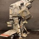
Here we go again! My last build was the Star Wars wall display, but for this one I'm sliding back to the kreiger universe. A stray comment on another thread led to the donation of an ancient built Airfix SRN1 Hovercraft by @TonyW. So very many thanks to Tony, and now lets see what I'm going to do with it. I saw a kreiger 'skimmer' type attack craft some time ago and quite liked it. I've stolen the word 'Spindizzy' from the James Blish 'Cities in Flight' Sci Fi novels of many years ago. Time to combine the two I think. After I'd stripped off all the unwanted bits of the model I was left with this basic form. This too was disassembled, various blobs of ancient tube glue were removed & mating surfaces rubbed smooth. Here are a couple of the removed air ducts and various other bits. After a good search of the spares boxes and various combinations of parts (Ooer!) I think I'm settled on this. Or something very like it anyway. The front is at the left here. The ribbed items may look familiar? They are from a Star Wars Slave One, cut in two. The oval bits to the right are pencil sharpeners. The driver sits here between these two shields. It may even be an armoured fighting suit (AFS). And from the back, the dome contains an Anti Grav unit, while the sharpeners provide steering thrust. They will be mounted higher and will use air sucked in via the big central fan. So far I think it all makes engineering sense (which, to me, is an important issue on these things). I think I do need to add fuel tanks somewhere though. Household management is in decorating mode, so modelling time may be short in the near future. I only get time at the weekends as it is. Please bear with me if this build stretches out into the future. Comments and suggestions are always welcome. Cheers, Pete
- 53 replies
-
- 15
-
-
- Maschinen Kreiger
- 1/35th
- (and 1 more)
-
I’m spoiled for choice here as I have at least a dozen biplanes in the stash, a Fokker DVIII a Tornado and a Lysander, I also want to build a Junkers parasol a South African AHRLAC and a Fokker DXII. But I think I’ll kick off with the Junkers. An all metal parasol fighter concept with a jettisonable fuel tank ( even up to WWII pilots were terrified of burning up) A prototype was started but never finished. Details are sketchy so it will be based on the plans above and detail from that Junkers JI/10 and DI. The wing will be corrugated and I’ll probably mold the fuselage. I want to get my four little jets complete before starting in on this but roll on August 7th.
-
I’ve wanted to build a piloted Mech/Powersuit with the driver in an open roll cage for a while now. I recently picked up a set of Polish tank crew figures and decided to have a go. I don’t really have a clear design in mind, other than I’d like to have exaggerated, cartoon proportions, with large arms and shoulders and small legs. Kind of like Bluto from the Popeye cartoons. I started by building the seat out of some leftover polystyrene scraps. The joysticks and foot rest are Gundam parts. They’re kind of chunky and possibly scale-breakers, but I’m playing this one fast and loose. Next, I built up a frame to support the huge arms. This was printed in five parts and assembled around the chair. On either side of the pilots head , I drilled the mounting holes for the roll cage. This will (hopefully) be bent up from some acrylic rod. A bit hard to see, but the black textured piece behind the drivers head is from a video cassette. I also filled out the back with sheet styrene and started to add some kit part details. Under the seat, I’ve added a piece to attach the legs to. I’m happy so far, but slightly unsettled as I have no real plan. I will trust that the Spare-box Muse will lead me down the golden path to kitbash Elysium. that’s it for now. Thanks for looking in. Pete
-
Another model of mine built from scratch some time ago. Let me know to stop when you feel spammed 😉 This time it's a "what if" project. 1:35 German WWII walker tank (fully built from scratch. Ok... almost. Few parts were from kits) The idea was to combine a German-style WWII tank and spider legs. Those of you who dealt with the German armoured vehicles will probably notice the Tiger inspiration. There are three legs because I hate to do repetitive elements so I made the minimum necessary to ensure stability. Initially it was supposed to be an Allied vehicle, which is why among the WIP photos there is one with a different turret. But I didn't like it so I built another turret. Enjoy W.
- 9 replies
-
- 17
-
-
- Scratchbuild
- what if?
- (and 1 more)
-
Well, here's what I've been up to for the last couple of months. I do love the Curtiss F9C. It's such a sporty little nugget. I've liked this aircraft for a long time. A real long time. Which is why I thought I'd try to do myself a favour and see if I can add one to my 1/144 scale collection. If I can finish it, it will be a nod to a much younger me and a lesson that its never too late to finish that which you have already started. Some builds sit on the Shelf of Doom. This one is almost part of the archaeological record, as I started making it in 1997. At the time there was precious little information to hand. No internet in my part of the world, and all references had to be sourced from an indifferent local library. I had some plans from a Putnam book on Curtiss aircraft and a 3-view drawing from a Rareplanes vacform kit in 1/72. Armed with those I gave it a red hot go. Materials were domestic and automotive for the most part. Some beech wood offcut was used for the fuselage (pretty well seasoned now, I suspect) and a precious bit of styrene for the wings. Primer and putty were from the car section at the hardware store, and resisted all but the most rigorous attempts at shaping and sanding. The bits of this poor incomplete Sparrowhawk have been with me for more than twenty years, and I can still remember the many hours I spent whittling and scraping it into shape. The much younger me always hoped to complete it one day. I think it's time it finally came together! Here's a couple of shots of it after I dug it out of an old biscuit tin. Lets see what we can make of it. Pretty manky! Over the years I have found some much better drawings and I was able to scan them at high res and reduce them down to 1/144 scale. Once that was done I began to check to accuracy of the work. To help do so I made a very simple jig from some plastic card which supported the aircraft with the upper edge of the card aligned to the level of the thrust line from nose to tail. I pinched this idea from a warbird restoration photo I saw in a magazine. It makes plotting and measuring a breeze! On my drawings I superimposed and identically-sized block that represented the position of the jig. By using the edges of the jig as a datum I could then accurately transfer measurements between the model and the plans. Things were looking pretty good at this stage (he said, blissfully unaware of what was about to happen next). The profile wasn't too bad. The headrest was .4mm too tall, and the tail was 1mm too low, but that wasn't a biggie. I was encouraged to find that the lower fuselage was pretty good, while the distance between the wings and their forward stagger was okay too. Happy times. Then I went to check the plan view... Oh dear god. What did I get myself into? The fuselage was way too wide. Like, Grumman wide. No scratch that. It was Mitsubishi Raiden wide! Looking at the plans and various walkaround photos, it was clear that the Sparrowhawk fuselage was barely shoulder width, whereas mine was a portly barrel of a thing. Something had to be done, so I reluctantly began trying to file it down. I started off as delicately as I could. Scraping through a veritable who's-who of primers, putties and adhesives. Eventually though things started to fall off, and before I had gotten even halfway there I had already dug clean through the side walls of the cockpit. I found with a bit of care I could preserve the upper bit of the cockpit edge. So I added some new side walls from .5mm styrene and flushed them in. Maybe it will work out okay Here's where it sat, as I leaned back in my squeaky chair and frowned at it after shaping the rest of the fuselage to trying to get the cross sections to match. Eventually the shapes came together and the whole thing received a generous coat of Tamiya grey and a rub back with 1200 grit wet and dry paper. I filled the original strut holes too and drilled some more accurate ones. It should make things easier later on. It's getting late here, so I'll add some more shots again soon. The fuselage has been reshaped and sanded. The side panels behind the cowling were added from sheet and flushed in. I also removed the tail and rear decking and made another one. The lower wings turned out to be too broad in span and too wide in chord, so I ended up reshaping these. To my surprise the tailplanes were actually rather good for shape, so I tacked them into position with tiny drops of PVA then backed the joins up with superglue once I was happy with the alignment. The old hinge lines for the ailerons are incorrect so these will get filled and scribed again. More later!
-
Starting to make some headway on a scratchbuild of the Norman Fieldmaster in 1/48 scale. Started off with the framing for the fuselage buck... Then the buck almost ready for vacforming. Shown alongside the Valom 1/48 Britten Norman Island for a size comparison... Then after vacforming. Split into front and rear sections for size practicalities. Front fuse moulded left/right halves per convention. Rear fuse moulded top/bottom - which is going to assist with building the interior as we see later... Then here' s the tail in a jig - with fuse under way in the background. Lego has the big advantage of being resiliently 'square' which comes in handy for modelling. And here are he basic component parts dry-fitted. Interior is being installed in the lower half with clear section to go over the top. The big plus of separating front and rear fuse halves (apart from moulding limitations) is that I can basically build the cockpit 'pod' as a hermetically sealed unit - without having to worry about plastic swarf, sanding detritus etc making their way inside and ultimately clinging like limpets to the canopy interior.The wings have separate 'trailing' flaps and ailerons which will add a bit more depth. And here's the scheme I will do - G-NACL on evaluation in Australia 1988 https://www.airliners.net/photo/Untitled/Norman-NAC-6-Fieldmaster/2513794 (a Daniel Tanner copyright photo on Airliners.Net)
- 37 replies
-
- 20
-
-
- 1/48
- Scratchbuild
- (and 1 more)
-
Hi All, I haven't lurked in this part of the forum for ages...good to be back! Due to a recent house move, I have a much-reduced modelling space, with no room for an airbrushing station. Therefore I decided dabble again in figure painting with brushes. I had an idea a while back about converting one of the Tamiya 1/16 figures to represent a modern US Navy carrier deck crewman, as US Naval aviation is a strong interest of mine. I liked the look of the brown-shirted 'chock and chain/plane captain' crewmen: So I bought the Tamiya Bundeswehr Tank Crewman figure set below, as they wear a similar-style helmet to the US Navy crewman. They also come with goggles, and as a bonus, there is a second figure in the box (though he has no legs!) The photo below shows the figure head with the tank crewman's helmet detail sanded down, and the other moulded details on the helmet removed. My plan is to convert the head and torso and sculpt new arms. I have not tried this before so it's a step into the unknown. Any help from experienced sculptors would be appreciated!
- 26 replies
-
- 6
-
-
- Tamiya
- scratchbuild
- (and 1 more)
-
Dear all, Here is my first effort at a scratch build. This is modelled on Bristol Scout 1264 which lives at Old Warden in the Shuttleworth Collection. When I first set eyes on this pretty little biplane I decided I had to make one in 1/32 but no kit was available so with the encouragement of a friend I dived headlong into the scratch building pond. Although it took just over a year, most of the time was spent scratching my head, rubbing my chin and staring blankly into space. It is by no means perfect and I could spend forever retouching and refining things but if I take my glasses off it looks terrific to me from a distance and most importantly I had so much fun with this project. To anybody contemplating scratch building I would highly recommend just having a go. The materials are cheap or free, for instance the cowling is the lid of a sauce bottle. Anything you cock up can always be remade and you will learn a lot, especially about the virtues of planning and patience but above all you will have great fun. What have you got to lose? Anyway enough my random ramblings, here are the photographs, I hope you like the Bristol Scout and are encouraged to learn about this wonderful aircraft and have a go at scratch building something. 1/32 Scratch built Bristol Scout by Richard Williams, on Flickr 1/32 Scratch built Bristol Scout by Richard Williams, on Flickr 1/32 Scratch built Bristol Scout by Richard Williams, on Flickr 1/32 Scratch built Bristol Scout by Richard Williams, on Flickr 1/32 Scratch built Bristol Scout by Richard Williams, on Flickr 1/32 Scratch built Bristol Scout by Richard Williams, on Flickr 1/32 Scratch built Bristol Scout by Richard Williams, on Flickr 1/32 Scratch built Bristol Scout by Richard Williams, on Flickr 1/32 Scratch built Bristol Scout by Richard Williams, on Flickr Many thanks for looking in. Here is a link to the build thread in case you are interested Richie
- 34 replies
-
- 34
-
-

-
- WW1
- Scratchbuild
- (and 1 more)
-
Here is my new project. This will (hopefully!) be a depiction of N220, the winner of the 1927 Schneider Trophy race. I started this one about a month ago and it has been progressing fairly well. Now that some of the more difficult parts are out of the way I thought it might be safe to show. It's a small aircraft - only about 47mm from nose to tail in this scale, but the shape is quite complex. So there were more than a few nights spent trying to get the outline and cross sections looking right. I started off with the fuselage outline. Marking it out on a sheet of 1.5mm styrene. The drawings date back to 1956 and seem to be the only game in town. Fortunately they compare very well to available photographs, and it looks like the original draughtsman poured his heart and soul into them. This was cut out and "cheeks" of styrene added either side to fill out the plan view. Some evergreen rod was added to form the core of the rear decking. Other strip was added for the upper fuselage fairing ahead of the cockpit and a lot of Mr Surfacer 1500 was brushed on to blend the contours in. It looks like rubbish right now, I know. But I swear... I am going somewhere with this! While the fuselage was drying the floats got a start as well. I used two bits of 3mm styrene sheet to make up the basic block. One side of the high impact styrene sheet has a hard, clear surface. I face these inwards when I laminate the pieces so it gives me a visible centre line and I don't accidentally sand things out of true. The plan view was shaped first. Once the top view was satisfactory the side view was marked out and the lower profile cut to shape and filed to the right contours. The step is made by masking off the rear section with three layers of Scotch tape (810D is best) and painting on several layers of Mr Surfacer to build up some thickness. A couple of days to dry and bit of a sand, then take the tape off. Once the underside is done it is safe to start shaping the top. I find if I start trying to shape things in the round from every angle at once it goes out of control very quickly. Doing the shape one profile at a time seems to be much less difficult. The floats got a final shaping and were scribed and sanded smooth. Extra details like the mooring points and circular inspection panels were added too. With the fuselage, I tried to keep the components separate for as long as possible. The windscreen was mocked up in solid styrene as a guide. I'll use it as a pattern for doing a clear one later. Putting things together for a trial run... Blending things in was tricky. It was made worse by the lack of suitable primer. The hobby stores round here have been picked clean, and due to covid they have not been restocked for the best part of a year. I was operating on the very last of my Tamiya primer, so I had to buy some Mr Surfacer 500 (the only stuff I could get). Unfortunately it is way too coarse for 1//144 and has a very gritty texture. Lots of work was needed to sand it back, as you can see here. I'll leave it at that for now. I hope you will like the progress so far. More later!
- 105 replies
-
- 34
-
-
- Schneider Trophy
- Scratchbuild
- (and 1 more)
-
As I've been promising, here is the start of another scratch build, this time the enemy, an S-boot also at 1:48th scale. The s-boot is actually almost the same length as the Fairmile B so the two will make an interesting companion pair when finished. There seem to be basically 5 broad types of s-boots The early war low forecastle boats (Airfix do a kit of this type), a few sub-types The early (really interim) high forecastle type S 30 (or type 26, I'm confused) with an upsweep to the forecastle at the sides of the bridge The mid war type 38 The later war type 38 with the armoured cupola (Kalotte) which evolved from an unarmoured cupola that was often retro-fitted to the type 38's The type 100 at the end of the war which is really the same as the type 38 armoured but with different armament and rear deck layout, build with the armoured cupola from the start Most models you see on line seem to be of the last type, but I rather like the type 38 before they stuck a hat on it so that's what I'm making. This was the main enemy boat in the middle years In my research, I've bought a few books (some I had already). To be honest most simply repeat the same stuff I've also bought every plan I can find Unsurprisingly, none are to 1:48th scale, however, these plans are... Thanks to CAD rescaling and an A1 print and post service. This is the early type 38 unarmoured and the one I will build, but forget the fancy paint job, seems that was mostly using in the Baltic, the channel boats were plain grey from what I've read. The Med boats had cool red and white stripes on the forecastle as did other Italian warships for aircraft recognition, but I think I'll stick with the channel flotillas as that is what the B and SGB would have encountered The various plans have 7, 9, 10 and lastly 20 sections for the lines. I've naturally gone with the 20 section lines per the scan below and re-drawn them This took a surprising amount of time (last 2-3 weeks between interruptions as the lines are really very subtle and lining these up with the other drawings had me redrawing them 3 times. The lines and the large drawing are 1:25 scale and came from Paul Stamm Modellbau in Saarbrucken in Germany. His package of information cost €62 but came with a disk full of drawings and pictures (finding a computer that had a disk drive was interesting...) and the line drawing above is from his drawing scanned and re-scaled. None of the drawings show sections which is a shame, this drawing is a Russian drawing of an early low forecastle type which is not particularly helpful However, in Paul's pack was this blue print which is actually really useful, if a little small So, that's where we begin, lets see how this turns out Steve
- 219 replies
-
- 13
-
-
- 1/48th
- Scratchbuild
- (and 1 more)
-
Due to illness (and the cold in the manshed) I've been quiet on the build front for a while. However, today, plastic seems to have been manhandled (ooer) and the smell of Tamiya extra thin has wafted about. This one has been nagging away in my brain for a couple of months now, and today I had an opportunity to do something about it. I'd gotten a couple of 'spares or repair' F-18's from the bay for less than a tenner. One Esci, the other a Chinese cheapo. 1/48th scale. One of them will form the basis of the Freighter. And, you may be wondering what a Vaurbian is? Sci Fi Wikki (probably) says... VAURBIAN FREIGHTER The type K-20 Vaurbian Freighter is a rare item in the Star Wars universe. No one seems to know who the Vaurbians were, Or the location Of their home system. All that seems to remain are these ships. Which seem to be at least hundreds of years old. The Freighters are controlled by what may be an A. I. (Artificial Intelligence) built into a sealed compartment in the hull. Although it may equallly be an Alien life form or even a Vaurbian. For the sake of convenience I’ll use the term A.I. The A.I navigates and controls the ship so there is no need for a bridge. Commerce etc is handled via comms by the AI. In some ships Humans are employed by the AI for cleaning and light maintenance, as well as cargo handling. They may even be a family unit. Others use robots. The FTL drive is totally unlike anything else seen in this universe. Empire ships etc just seem to turn up the gas to number 11 and vanish. Vaurbian FTL seems to operate in a very strange way, but the AI always knows where and when it is. The drive can also be used as a weapon. It seems that no one who tried to attack one of these freighters in the past has ever been heard of again. Hence the lack of external weapons. The ships are fully atmosphere capable, so can deliver their cargo virtually anywhere. Given the size of the Empire, Freighters are always in demand. And so, some pictures of progress so far... Some boxes of bits. some of which have been donated by fellow Britmodellers. My thanks to all. More bits being kept close to hand. These will be used to disguise the basic Aeroplane (hopefully). The basic Aeroplane. The ship will be this way up, but the back becomes the front. I've made a start already, The green Gazelle bits seen here at the back have been glued on. It felt good to get something done, though I don't know when the next episode will go to press. Thanks for looking in. I hope to be back soon. Pete.
-
 Hello all, I’m about 4 months in on my Lambda now and here is the progress so far… https://www.flickr.com/photos/191884247@N07/shares/s67s79
- 43 replies
-
- 3
-
-
- Star Wars
- Lambda-class shuttle
- (and 1 more)
-
 I've always wanted to get the Aoshima 1/24 Road Warrior kit of this car. It seems like I missed the boat, they are very expensive on ebay. I checked shapeways hoping they would sell a 3D printed body and they do, but even their 1/64 scale body is expensive. So I figured I'd take a run at scratchbuilding it in my favourite scale. I've carved wooden molds for vacuforming with some success. I'm going to try carving the car out of wood. I would usually use basswood (aka lime, linden) but I have this birch which I've been carving spoons from lately. It's harder than basswood but still carves very nicely. After splitting, running it through the jointer and table saw I have this block that's slightly oversize. I've brought it inside to let it dry out for a couple weeks before I start working on it.
 -
 Hogwart's Express - A Baby Bandsaw Build 'A scarlet steam engine was waiting next to a platform packed with people. A sign overhead said Hogwarts Express, 11 o'clock. Harry looked behind him and saw a wrought-iron archway where the ticket box had been, with the words Platform Nine and Three-Quarters on it. He had done it' So wrote J.K. Rowling in chapter six of her 1997 novel Harry Potter and the Philosopher's Stone - the first in a series of novels that some of you may have heard of. My two daughters have definitely heard of these books - and have seen the films countless times - in fact they are bordering on fanatical about all things Harry Potter. So it wasn't a complete surprise when the younger of them - twelve year old 'Baby Bandsaw'- came to me about two weeks ago and asked if she could have a go at scratch-building a model of the Hogwarts Express. Being a very irresponsible parent I immediately decided that this was a great idea and despite all of the hazards of power-tools and chisels and so-forth, Baby Bandsaw (B,B) should indeed have a crack at this! We agreed that I would give her inexpert guidance, bad advice and, whenever required, inept help. She however would actually do the majority of the work. This will be Baby Bandsaw's Build, not mine, but she agreed that I was allowed to photograph and document her progress right here on Britmodeller and that I would be allowed to publish under my log-on. I looked her straight in the eye and asked her 'if you start this will you finish it?' it was a somber moment - she said 'yes' so we shook hands and the project began. After a brief bit of research and a couple of internet searchs I found this set of plans for a 'Hall Class' locomotive (Olton Hall was used in the film) and re-scaled the plans to 1/48 scale using my work's photocopier. This should be enough to get started. In model railway world I think that 1/48 is called 'O' gauge for some obscure reason. This lump of Huon Pine - the same bit I used to form the vac-form cowling buck on the Avro 504 - was the only bit of decent wood I had that was wide enough to start to form the boiler . Here is the first cut in the entire project. BB cutting off a small surplus lump on one end, squaring up the block in preparation for further work. Here she's cutting out the profile view of the boiler. We have no plan view at this stage but that's not too much of a handicap because the boiler is circular in cross-section and so the side view is identical to the plan. As per my usual 'modus operandi' BB is spraying some cheap photo-fixative glue onto the side of the wood so that... She can stick the paper pattern on and start some bandsaw action! I was sort-of a bit 'parental' here and fussed about making sure those fingers stayed at least a small distance from the blade! A few minutes later she had this. We marked up a 'do not cut into' red line -as you can see below - and a grey 'remove with chisel' area and BB started hacking into the sharp squared off corners with this scoop chisel - nice work! So after about half an hour she was left with this. The very, very early stages of this build. The very first bit of rounding off of that square block that will need be reduced to a full cylinder to represent the boiler. Alas, by now it was bedtime as BB had school the following day. So begins my first post on the 'Civilian Vehicle's forum - a forum I have been hankering to get onto for some time. Some of you may be thinking 'Ere! Isn't there a forum specifically for railway locomotives on Britmodeller?' and there is. However, frankly, it's a bit hidden away and BB and I are hoping for a bit of visibility, interest and banter regarding this project. We think it will do better here in that regard. I did send a Personal Message to @Mike and he has very graciously given us permission to post this here so we aren't trespassing - honest! 🙂 Anyway - this should be fun, and I hope some of you see fit to follow along and see what comes of this. Best Regards, Baby Bandsaw and Bandsaw Steve!
- 387 replies
-
- 21
-
-
- Scratchbuild
- Wood
- (and 1 more)
-
Hi all, Since I built my Defiant I’m now on a turret roll, so I’m going to drag myself kicking & screaming from my OOB comfort zone and attempt to build Hobby Boss’ “British Fleet Air Arm Avenger MkI” as an FAA Tarpon. From what I can tell, Hobby Boss have taken their “standard” US Avenger kit, sourced a new set of decals, made up a couple of paint schemes and issued it as an FAA version. All of the shortcomings and errors of this version of the kit have been well documented – thanks to @tonyot, @85sqn, @trickyrich and others for easing my journey of discovery with their excellent and insightful information (see below). Armed with that rapidly assimilated wisdom here is the kit box: Shots of the sprues – the detail level and crispness of the parts all bode pretty well: Transparencies – again, very nice: Kit decals – not so nice. Not convinced of the accuracy of these – the red of the national insignia alone is quite hallucinogenic. They’ll go straight into the dodgy pile… I’ve sourced a couple of extras for the build; Eduard instrument panel (which is intended for the Accurate Miniatures kit, so we’ll see how that goes), Eduard masks (a must for all that glazing!) and Eduard harnesses. So Eduard everything, basically. I’ve been hankering after a BPF build, so I’ve decided to model this aircraft; JZ257 of 849 Sqn, HMS Victorious, January 1945. I believe that this aircraft would have taken part in the Operation Meridian raid on the Palembang oil refinery in January 1945 (849 Sqn was certainly involved). Here’s a shot of Tarpons on that raid (albeit from a different squadron flying off HMS Illustrious): From what I can tell, JZ257 was one of the second batch of 200 Avenger MkIs delivered to the FAA. The aircraft would therefore have been equivalent to a Grumman-manufactured TBF-1C. This aircraft would have had the following configuration: - 2 x 0.50” machine guns mounted in the wing roots, as opposed to the single cowling-mounted gun of the earlier batch. The kit has these gun ports - ü. - Observer’s position in the central cockpit, including radar scope and plotting table. The kit as it stands is configured as a ‘standard’ US aircraft with electronics in place of the Observer position, so this is where the major surgery needs to happen. This will be my first real attempt at scratch building, so I’ll give it my best shot! Grumman-built aircraft had the cockpit, Observer’s position and turret interior painted in Bronze-Green. - The remainder of the aircraft interior including the bomb bay was painted Interior Green (with the exception of the cowling interior, which was Light Grey). - I have seen varying claims that the undercarriage and bays were painted Insignia White, the underside colour or even Zinc Chromate Yellow. The colour photo showing the faded paintwork a bit later looks to me like white might be the go – it’s definitely not ZCY (although other Eastern-manufactured aircraft could have had this configuration). - There is varying information around the ventral 0.3” gun (and whether it was replaced with an F24 camera). I’m going to stick with the gun – the decal sheet shows it in place so it must be right, right? - Round blister windows over the original window cavities. These provided significant improvements in visibility – they’re nicely shown in the shot below (forward of the access door): The kit windows are as fitted to the original batch of MkIs so are incorrect. I’m going to try crash-moulding these blisters, which could be interesting (think I’ll leave that til last) In terms of paint finish, from what I can tell the Grumman aircraft would have been finished in ‘standard’ FAA colours i.e. Dark Slate Grey and Extra Dark Sea Grey over Sky – I will be using these colours as opposed to those recommended on the Xtradecals ‘Yanks with Roundels’ sheet (although the decals look to be excellent otherwise). I also see a Corsair and Hellcat somewhere in my future 😉 It’s well documented that most BPF aircraft were heavily weathered and faded so I’ll push my weathering skills to the limit. The shot below is a great guide as to the level of fading of the paintwork, as well as being a very evocative shot of the conditions in which the aircraft (and crews) operated from temporary land bases (Ceylon, I’m guessing?). Another one (showing a Hellcat, but you get the general idea). It’s interesting to note that there’s very little bare metal on show, though the paint has worn through to the zinc chromate primer in heavy-wear areas. I might try and replicate that effect. And a couple of nice reference shots: The camo demarcation looks to be pretty hard from the above shot, so no freestylie on the airbrush… The kit contains a number of ordnance options including rockets, torpedo, depth charges and 500lb bombs. I’m guessing the Tarpons on the Palembang raid would have used the latter (and the kit rockets are bobbins), so I intend to do the same as shown above. From what I have read Hellcats & Corsairs took the role of combat air patrol and ground attack on that raid, so it kind of makes sense that the Tarpons would be bombing (along with Barracudas, if memory serves). The raid is detailed in the excellent ‘Carrier Pilot’ by Norman Hanson, which is well worth a read. So with all that under my belt I shall gird my loins and crack on with the build! Thanks for looking – until next time, Roger
- 64 replies
-
- 12
-
-
- HobbyBoss
- Scratchbuild
- (and 1 more)
-
Hey y'all, so I picked up a partially 'built' Hase F111C on the auction site for cheap. Naturally it was missing parts, the entire nose gear leg and struts plus wheels, and one of it's engine/exhausts, I've already got a resin wheel set on the way and plan to scratch build the nose gear strut/leg assembly with spare parts and plasticard rod, and I've got a nice Resin F model engine/exhaust set on the way as well. pretty much everything else was there, all structural and aerodynamic parts are. Except the glove vanes/canards/leading strakes where the swing wing shoulder meets the fuselage, both of those pointy bits are missing, and I don't think anyone makes a replacement for those, and they are rather aesthetically important, so I'm going to have to scratch build them. I'm wondering if any has ideas of tips on scratch building curved aerodynamic parts like that. My other question is, what external differences are there between C and F 'Varks besides the engines, I got the F model resin parts because they were cheaper, and also the F is a little cooler I guess. So I was wondering if there is any small external changes I should make to conform to the F aesthetic. From the Initial Pics on Ebay you can see the Fuselage wasn't in good shape, it was worse in person: This is Her Current State, I've disassembled the fuselage roof plate and the intakes, add the main gear bay ceiling, then I've reattached them all with modern Plastic Cement (Tamiya extra thin) rather than whatever yellow adhesive was used before, and I broke out my clamps and also finger held the slightly bent belly in place to even out the sides and most huge gaps are close and things are a much tighter stronger fit, I also assembled one wing to test fit the wing slot and fitment on the fuselage, same with de-sprueing the vertical and horizontal stabs and checking fitment:
-
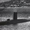
Continuing with a local history lesson.... In days of yore before the widespread use of wireless telegraphy. Vessels sailing from far off parts would have instructions to make for Falmouth or Queenstown for orders. The cargo may well have changed hands many times on the long passage home. Out of this grew a fleet of service boats based at Falmouth Quay. They were traditionally yawl rigged with a low main mast and a high set gaff, to save them from fouling the rigging of the sailing boats they were going alongside..Not only did they pass sailing orders but transferred personel , fresh produce etc etc. Falmouth Quay AS a base for this I have upcycled a 28' wooden boat I built some time ago. The plan view is good but the draft is not deep enough, not a problem as she will be displayed waterline The first job was to remove tops of the side frames as they were well over scale even for the original model in my opinion. They scaled out at 5 x 4" Deck beams added I hope you will join me on this voyage Stay safe Kev
-
I've been meaning to post this ongoing build for ages, but sheesh! Its so hard to come up with a title sometimes. I wanted to kick it off with some cracking wordplay, but alas I can’t think of anything 🤔 Perhaps its just best to rip the lid off and get on with it. These are a pair of Pfalz D.III and D.IIIa scouts that I've been doing from scratch over the past 18 months or so. Over the Christmas break I finally managed to get them out of the grey primer doldrums and into their top coats before all the fun stuff starts. Here's where one of them is at right now.... And here's how they got there: The idea was to do a D.IIIa initially. That's the later version with the two spandaus sitting on top of the fuselage decking, plus a larger tailplane and rounded wingtips. A short way into it I suffered scratchbuilder's remorse when I discovered that the schemes I liked best were for the earlier D.III version, with a smaller tailplane, pointy wingtips and the spandaus buried inside the fuselage (!). So I dithered around for a while, and eventually decided to have a go at both. Plucky fellow... The fuselage is basically the same for both versions. So I thought if I could get past my ripping allergy to resin I could replicate it and convert one casting to the other. I started off marking the fuselage profile up on a sandwich of two pieces of 3mm styrene and carved the basic fuselage to shape. Wing stock was made from acrylic so it wouldn't bend and the under-camber was made by scraping the shape in with an old steel ruler that had the end filed to the correct profile. I set the wing up against a straight edge so I could scrape along the whole length of the stock in a straight line. One of the good things about 1/144 scale is there is exponentially less mess and elbow work involved in jobs like this. The fuselage was mounted in a jig, which exactly matched a similarly shaped jig on my drawings. More about that on the first post here: https://www.britmodeller.com/forums/index.php?/topic/235062073-sparrowhawk-more-like-microhawk/ This made transferring dimensions easy as there were a lot of bits in close proximity, which would have been tricky to align otherwise. Details like the little round inspection panels are made from discs of decal film that have been thickened up with primer. I sharpened the end of some brass tube by reaming out the inside with a scalpel to create a mini punch. The wing ribs were made with primer too. More on that in the Sparrowhawk topic too if you want to learn more. I made a mould in silicone and cast some copies. A bit of a learning curve there, but eventually I got a couple of useable wings. Much better! At about this time I stopped to work on the Miles Magister for the BM 1940 GB. Later however I was able to bang out a couple of fuselages and keep going. One was converted back to the earlier D.III and other bits like the guns and engines were made too. Posting an image of a model next to a coin of unfamiliar currency drives people nuts over at Hyperscale... Well dear reader. That's pretty much where I got with them up until Christmas. During the break I've been able to put some extra time in, and have got them to the painting & decal stage. I was super nervous about the surface finish for the Pfalz silver-grey and scrubbed like I was prepping for surgery when it was time to do the base coat. I bought a set of 1/144 crosses some time ago from a company called Mark I. Most of them are not fit for purpose as the white outlines are well out of register. I hoped I could at least trim one pair down to a consistent width for the tail of Hecht's machine. Then I realised any I stuffed up could be used as a 2nd chance to make the plain black crosses for the Buddecke D.IIIa that I planned to do. I decided to give it a try and it seemed to work. Providing I had enough magnification and a sharp enough scalpel. Speaking of magnification: I took a broken pair of super cheap 6x reading glasses that I use and stuck one of the lenses onto the front of another 6x pair. I now have access to 12x magnification... Look out world! And that pretty much brings us back around to where things are at now. Loads more stuff to do, but they are coming together nicely now. Sorry for the picture heavy presentation. I was hoping to get the saga up to speed as quickly as possible so we can do the rest at a more relaxed pace.
-
This one was started in early November and I took the final pictures yesterday. I am indebted to @SafetyDad . I've wanted the Fledermaus version for years but it's rather expensive. My intention was to scratchbuild one, but then Padraic sent me a gluebomb Hornisse he'd found on the web. This is it as designed by Kow Yokoyama . the 'Father' of Maschinen Kreiger. It carries an Armoured Fighting Suit (AFS). To make more of a profit Nitto took the basic mould and changed it to make the Hummel (A sort of Drone) and the (Manned) Fledermaus versions. which was rather naughty of them. Anyway, I set to and, after dismantling the kit, I couldn't help but improve the design into a more practical flying machine. The original had five large rocket motors, which our man in Kalamazoo observed would, "suck it inside out in seconds'. I kept the one at the back, rebuilt most of the underside, and added jets & a forward fuselage and cockpit to 1/20th scale. Here we are ready to fire up the lift engines and go out hunting Falkes. I've done a typical kreiger rough paint job as if it was built up from parts by rebel forces. Yes, it's an ex Harrier rocket pod. The landing gear is part original/part scratchbuilt. Springs are ex Biro! The nose cannon. The breech etc is somewhere under the cockpit. Ammo behind the pilot. On the RH pylon is a large missile with a rusty seeker head. Upper fuselage. At right is a spoiler/airbrake painted orange. And rocket thruster at the back. The thruster would take this up to altitude, rather like an Me 163. But, with the jets, it would make a powered landing. Taken during the build, this shows the wingtip tanks. Part droptank, part 1/32nd P-38 tailboom A bit of battle damage repaired with speedtape. Bits for this build came from all over. This tailplane is ex 1/32nd Me262. At left, an engine exhaust. Made from three bits of car wheel, and in the middle is part of a 1/1 scale tyre valve. The oval bit is a tiny ships dinghy. The rocket motor parts, here at centre, are original to the model. Underneath is two shades of light grey, dabbed onto white primer with sponge. The central dome is an anti gravity generator. Also visible are the three lift thrusters which use engine bleed air to assist in take off and landing. The rusty seeker head. It was part of a ball point pen. The top surface is grey primer with Tamiya dark yellow dabbed on. Various greeblies dress things up here. The canopy. Not the best bit, you can see the side window bowed in It's stuck on with industrial superglue so would be wrecked if I tried to remove it for repair. That might still happen. We shall see. Here's a picture of the pilot (made from Tamiya Pit Crew figure parts) and his scratchbuilt ejection seat taken during the build. Overall I enjoyed the build. The canopy is a disappointment though as it also has sanding dust stuck inside. These pictures aren't the best due to lack of light in the manshed. Pictures outside are not possible due to weather! There is a build log in the work in progress section. So you can see more of this if you are curious. My thanks to all who dropped by during the build, and, of course, to Padraic who made it all possible. Next up, I have the AFS which came with the kit. It too is a glue bomb (all three windows have glue on them) so it will also be a challenge to get right. But I can also use it as a pattern for replacement and spare parts. Bonus! Thanks very much for looking in, I'm always grateful for comments and will answer any questions if I can. Cheers, Pete Thanks for looking
- 17 replies
-
- 19
-
-
- kreiger
- Fledermaus
- (and 1 more)