Search the Community
Showing results for tags 'Scratchbuild'.
-
 Time for me to start my GB contributions in earnest… So this is in the stash and I’m almost caught up on my other GB commits and both my Drakken and Vampire are very nearly finished. Now it always my suggestion to be Airco and DaHavilland, so I thought I’d scratch build a DH1 side by side with the DH2, upon which it was based. So I’m off scaling plans. My first surprise, the DH1 is 4 meters wider than the DH2.
 -
Hi folks, I am planning to scratchbuild a Sikorsky S-61N helicopter but am lacking some details. I have plenty of Plan and Profile diagrams but do not have any cross-section views, which would be needed for me to get the contours and dimensions right. Can anyone here help with such information, measurements and frame/cross-section plans please? cheers Mike
-
And it’s done! After just over a year, a lot of plastic card, a Costa’s-worth of coffee stirrers and millions of tiny rivet balls I’ve finally decided that my Mk 1 Gun carrier is finished. It was a great fun project and I learned a lot. Everything is scratchbuilt apart from most of the figures. The large chap with the leather jerkin was scratchbuilt (well, his legs, arms and torso were) but the others are cheap knock-off resin figures. I tried to replicate a photo of “Darlington” cresting a small ridge while the top brass look on. I’m happy that I’ve pretty much captured the look although I shied away from covering the whole vehicle with quite as much kit as is shown in the photo. Painting was done using mainly Tamiya paints, with weathering being mostly oil paints with a little clay wash and a dab of pastel dust. I constructed it so that the upper hull can be removed to show the interior off. Things I’d like to improve next time…. Figures; there’s always room for improvement there. I’m very slowly getting better, but there still seems to be miles to go. Groundwork; this was my first attempt at painting grass and earth on a black-primed base and I’m not 100% convinced that this is better than using coloured static grass. I might try a hybrid approach next time. Foliage; my little bush is a bit sad, and the (real) cow parsley I used to represent real cow parsley isn’t particularly convincing I don’t think. Thanks to everyone who followed and provided brilliant advice, feedback and support during this extended build. The (12 page) WIP can be found here….. Mk1 gun carrier scratchbuild - Work in Progress - Armour - Britmodeller.com
-
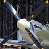
Gidday All, I've decided to give this Blitzenbuild GB a go, my first although I have done other GBs in the past. Usually I build model ships but I thought I'd be pushing it to do one in 24 hours so I'll do an aircraft instead. I've decided to try and scratch build a Grumman F7F Tigercat in 1/600 scale. The Tigercat was designed as a very fast heavily armed carrier-bourne fighter, however it never operated from aircraft carriers that I'm aware of. It's main problem was directional instability when trying to land with only one engine. Due to this it failed to gain carrier qualification and hence operated from land bases only. I've made three aircraft in this scale before, as trials for making air groups for 1/600 scale aircraft carriers I wish to make someday. These are the Grumman Wildcat (Martlet), the Supermarine Spitfire and the Vought Corsair. As the Tigercat never operated from carriers this aircraft may seem a strange choice but - I like it. Anyway, below is the traditional photo of 'kit parts' and 'instructions'. 😁 Well, that's it for now. I plan to start tomorrow, and I stress the words "plan to". I'm a volunteer bushfire fighter and tomorrow the forecast temperature is 44 degrees C with strong NE winds - the worst combination for Perth in West Oz. I live just out of Perth in the hills, surrounded by state forest. My plans might change very abruptly - we'll see. So until tomorrow, stay safe and regards to all, Jeff.
-
Kick-off Hello, I have spent the last 6 months working on a scratchbuilt Mig 15 and that project is now drawing to a close. http://www.britmodeller.com/forums/index.php?/topic/235012524-mig-15-scratchbuild/& Consequently, I've been thinking a lot about my next project and after much deliberation, including considering a very, very wide range of possible subjects, I have decided to try something completely different to my usual aviation related fare. I am going to try to build His Majesty's Australian Submarine AE2. This is a project that I has been in the back of my mind for over a decade now and when a fellow modeller offered to lend the following set of plans to me, all thoughts of other projects evaporated. In my view Allied submarines in WW1 are under represented in the modelling world, so I'm going to try to do my little bit to correct this. AE2 was an early E-Class submarine operated by the Royal Australian Navy. On the evening of 25 April 1915 (while the Gallipoli landings were underway) she successfully penetrated the extremely formidable Turkish defences in the Dardenelles Straight and proceeded to 'run amok' in the sea of Marmara. During a short-lived but very intensive period of raiding she caused considerable disruption to Turkish attempts to reinforce and supply their defences on the Gallipoli peninsula. On the 30th of April AE2 was damaged by the Turkish torpedo boat Sultanhisar and, unable to dive to safety, her captain decided to scuttle her. All hands survived the scuttling and spent the rest of the war as P.O.W's in Turkey where they suffered terribly. Four of the vessel's compliment of 32 died during their incarceration. In 1998 the wreck of the AE2 was located and found to be in remarkably good condition, mostly due to it's partial immersion in anoxic mud. A thorough campaign to preserve the wreck in-situ continues to this day. The possibility of recovering the wreck has been discussed at length, and although probably technically feasible would be a very high risk and highly expensive project. So - in the meantime a model will have to do! I have not yet started any physical construction - so there's not a lot to see yet but, most unlike me, I have been conducting some additional research. And just as well too because it turns out that the drawings above are for a mid-war configuration E-class submarine which in some significant regards was different to the early war AE2. For example, the mid war submarine had a gun mounted ahead of the conning tower and had two forward torpedo tubes instead of AE2's single tube. There are other differences also. Suffice to say that this set of plans from the RAN's historical page on their website will help me nail down the correct configuration. The model itself will be: 1 / 100 scale Waterline - surface trim Scratchbuilt - although I might resort to some aftermarket details here and there. It will not be a cutaway (despite various people suggesting the idea) Predominantly made from wood, but expect to see some brass and plastic sheeting and a few other bits and pieces as well. I am hoping to have physical construction under-way this week and am aiming to have it finished by the end of 2017 but really don't have any idea how long this will take as I'm completely new to this maritime modelling lark. My plan for this job is basically to 'muddle through' so any encouragement and expert advice from the sidelines will be most appreciated! Best Regards, Reconcilor
- 471 replies
-
- 15
-

-
- WW1
- Scratchbuild
- (and 1 more)
-
 Panzerhaubitzer 2000 - Pzh 2000 in the 1980s the German, Italian and British governments attempted to develop, in collaboration, the next generation of NATO self-propelled Artillery. For various reasons that project failed. Britain pressed on and successfully developed the AS-90 while the Germans pursued their own project which combined the expertise of leading German companies, Wegmann, Krauss-Maffei and Rheinmetall to produce the truly awesome Panzerhaubitze 2000. In the 1990's this was arguably the best Self Propelled Gun in the world and it remains a cutting-edge weapon to this day. Today it is used by several NATO nations including; Germany, Holland, Italy, Greece, Lithuania, Croatia and Hungary. The Pzh 2000 features an extremely long - 52 calibre - 155mm gun with a largely automated gun-loading mechanism for very high rates of fire to ranges in excess of 40km. The weapon's fire-control is among the most sophisticated in the world, and allows a single gun to be fired in 'multiple round, simultaneous impact' or MRSI mode. In this mode up to five shells can be fired, each with its own charge and trajectory in such a fashion that all five shells hit the same target at the same moment. The gun is also capable of firing GPS-guided precision rounds with a circular impact error of about 1.5m. The Pzh 2000 has seen a significant amount of action in Afghanistan where both Dutch and German examples have been used to provide fire-support to the International Security Assistance Force. This was the first time that the German Army has used artillery in combat since the end of WW2. One day while on my lunch break (long before all this COVID 19 business broke out) I was checking out a little-visited corner of the local gaming / model / bookshop and found this in among a pile of largely neglected publications. Upon opening the book I was greeted with this fold-out (and there are front and rear views on the flip side too). Now this might just be the most exciting centre-fold I've ever seen. In any case, a few minutes later the book was purchased. About a week later I had decided that this project was going ahead but that 1/35 just wasn't big enough. I took the book to my local printing / copying shop and got the drawings enlarged to 1/24 scale and copied 8 times. I got one 'master set' laminated. And now we are off... Let's scratchbuild one of these things! This is going to be an unusual build for me because much of the work will be done in plastic card, but I want a good solid wooden hull to work from so I'm starting with this block of 'Liquid Ambar' - a superb carving wood - which needs to be cut to the correct size. Here's the first cut of the entire project. Here's the interpreted curve on the leading edge of the hull being marked out... and here it is being carved to shape. Then rasped prior to a final filing and sanding smooth. OK - looks about right. Now I use the bandsaw to cut the wood to exactly the correct width for the hull. The bandsaw! Best tool in the shed! And following a bit of research (especially looking at photos) and some ‘interpretive’ carving and cutting at the rear of the hull I have this basic starting point. After two years of slaving away building a WW1 Biplane (an Avro 504 to be precise) I'm dead keen to work on this project which promises a complete change of subject and modelling method. I hope that some of you will follow along and see what comes of this little venture. Bandsaw Steve
- 482 replies
-
- 28
-
-
- Artillery
- Scratchbuild
- (and 1 more)
-
 Time for another scratchbuild. Most de Havilland aficionados would be familiar with the DH104 Dove and DH114 Heron. Quoting Geoff Goodall: "At the end of World War Two, the Australian associate of the parent De Havilland company, De Havilland Aircraft Pty Ltd at Sydney NSW (referred to as DHA) was completing wartime RAAF Mosquito orders and looking for a new design to build for the post-war civil market. The general concept was a single-pilot utility transport for 8 passengers as a replacement for the many DH.84 Dragon biplanes in use in Australia. It was to be of simple rugged construction with fixed undercarriage suitable for Outback operations on rough airstrips, with low-powered 145hp DH Gipsy Major 10 Mk.2 engines, which were in plentiful supply. The new aircraft was the DHA-3 Drover....." (source: https://www.goodall.com.au/australian-aviation/drover/drover.htm for much much more....) Below is a photo (credit: Geoff Goodall) - which bears more than a passing similarity to the Dove, and is of a similar size - but with an extra engine. Actually the Drover had very little in common with the Dove other than stressed skin construction concept. Much more on this at the URL provided above... From a modelling perspective - whilst the Dove has been well served (certainly of late) in 1/72 - the Drover less so. There's a number of modelling articles where people have converted a Dove to a Drover, and older articles converting the Airfix Heron to a Drover (and the Airfix Heron to a Dove) - basically major cut and shut surgery. But I wanted a 1/48 model (my preferred scale) and so we turn to scratchbuilding. First problem was getting decent plans - the best I could find was some 'thumbnail plans' - not sure of source but might well be Jane's or similar. These don't respond well to enlargement (the pen lines scale out at about 6" thick), and there were aspects of these drawings just didn't look 'right'. I know Air Britain has a publication on the Drover with drawings from Juanita Franzi which are sure to be great - but it'll take me a while to source that locally (or pay o/s postage!!), and there's a model to be started! Luckily there's a number of airframes in Australia - including a mostly complete Drover, and a fuselage at Queensland Air Museum in Caloundra. So it was a museum visit, and out with a camera, tape measure, pen and paper. The scribblings below was the result of the visit - the drawing at left the enlarged thumbnail plans I was starting with.. Anyway - after translating all this lot to 1/48 - here's what the fuselage plan looks like - top view, side view and cross sections. This was my main concern with the thumbnail plans and there's certainly some differences... So - let's cut some plastic! The fuselage has compound curves all over the place - which is going to require vacforming. And vacforming means I need a 'buck' of the fuselage. My technique here is to first build up a skeleton of side view, top view and cross sections - which we'll later fill in with 'car bog'. You'll see this happen over subsequent posts. Below is the skeleton being built up. I've cut the side view as a single piece (0.75mm styrene) and am adding the cross-sections out of 0.5mm styrene - half on the port side, the other half on the starboard side - with a 0.75mm sliver removed to allow for thickness of the side view piece.... Little triangles of styrene help provide structure and keep things at right angles. And here's what it looks like with all the pieces of the skeleton in place. It'll need some time to dry before I fill it in. So let's move to the flying surfaces - a few hours work required to get the component parts as you see them below. - wing top surfaces (0.75mm styrene), bottom surfaces (1.0mm styrene) and the empennage pieces (all 0.75mm styrene). - All the trailing edges have had their inner surfaces sanded to a fine taper with wet & dry sandpaper. - I've also built up a tapered spar (basically an I-beam), and a tapered leading edge (laminated 1.5mm styrene) And in about 15 minutes - all the trailing edges are glued and clamped. Main spar is tacked in place, and temporary spars have been used for empennage. This now needs time to properly dry as the process of glueing the leading edge is going to put a bit of stress on this glue joint (done it before - it works fine). That'll do for the first post. Next steps. - start backfilling the vacform buck with car bog. - glue the leading edges of the flying surfaces.
- 122 replies
-
- 28
-
-
- Drover
- Scratchbuild
- (and 1 more)
-
 This is probably my first model that I have completed since I joined Britmodeller almost two year ago . There are some of my things in RFI but done before. P.E.A.C.H. was pretty quick project by my standards: I finished it in three months. That's the combination of trashbash, kitbash and scratchbuild. The build log is here The base is ready too. It's basically a separaet model, a mini diorama, so I briefly considered putting its RFI in the diorama section. But PEACH and the base started together, so they will finish together. Thanks for accompanying me in this work. Regards Wiesiek
 -
I don't have the enthusiasm to finish my current projects, but I'm tempted by the workbench (apparently I'm best at doing rather than finishing 😉). So I started another project. The intention is to build an armed low-wing hover/jet with a vertical profile (height greater than length). The shape on the front is supposed to roughly resemble an inverted T). It will be a combination of trashbash kitbash and scratchbuild, because I want to use scrap and spare parts, but to compose it well I also need a lot of styrene constructions. A few days ago I was cleaning my room and found two things. First was an old Dell PC mouse (which I kept because it has a great shape). Second was the Academy MiG-29 1:48 kit (scrap I got from a friend). It occurred to me to combine these two things. Or at least to use some parts from the MiG. The model is in bad condition: missing parts, no decals, poorly glued elements. I decided to use the wings pictured in the middle and a few other parts. At this stage, I also gave up using black mouse overlays (clicking element). The easiest way would be to glue the wings to the mouse but I don't think it would look good. So I needed connecting elements. As it is not easy to combine a rounded mouse to flat sheets of styrene, this "connector" is constantly growing and becoming more and more complicated This part is an extended wing attachment at the initial stage. It has a sandwich form to make it look better. The hole in the center is the landing gear section. The triangular structure on top is the lower fuselage element. The mouse will be angled approximately 30-40 degrees to the wings to add dynamism to the ship's outline. Here you can see the next stage of building the fuselage. I glued a styrene wheel to the lower section, and on it I started to build the middle section (where the mouse will be placed). The ribbed gray elements are the air outlets from MiG (only one is visible here). The styrene rods are matched to the screw holes in the mouse, which makes it easy to fit and remove. Other gray elements are parts of some plane or helicopter from my resources. I put the cable cover only for the photo, I will glue it after painting the cables. The Fulcrum's air outlets are clearly visible here. On the right: part of the fuselage of another unidentified plane. Attaching the engine nozzle caused me the most problems. First I had to make the bottom part of the mouse. It only worked the second time. I used another styrene wheel but the mouse is not completely flat so it didn't fit perfectly (there were gaps). I masked them with a narrow strip of styrene. Around the mouse there is a groove for attaching the lower part, which greatly facilitated the attachment of the strap. Then I glued a nozzle to the wheel. As you can see: it doesn't fit well either, but it's the only part of this nozzle I have, so I had to use styrene again. I decided that I could not make a cylinder of such a complex shape so I decided to go a different way. It took me about a week to build so far. The fuselage is basically ready for the applying details (kitbash phase). The two big tasks for the near future are landing gear and cockpit. Especially the cockpit can be problematic, because I would like it to be glazed. I have some canopies but it will be difficult to fit them to the mouse. Cheers. Wiesiek.
-
May I present LNER A4 Sir Nigel Gresley carved from parana pine with boxwood wheels, all hand carved. The drive wheels were the biggset challenge, having to carve 120 spokes with a scalpel in tough boxwood, I got through about 15 blades. Everything else was pretty straightforward. Theres no detail in the cab as at some point I plan to add a tender, which will obscure the view. Not made to any particular scale, its about 9" long as thats how big the plans were when printed out. Thanks for watching, all feedback gratefully received.
-
Hi folks…! Well the dust has thoroughly settled on my Pierce Arrow AA truck, and so it’s time to consider the next project. I had a bit of a palate-cleanser in the form of the Vickers gun crew that I bought to provide a decent machine gun to clone for the last scratchbuild. I stuck the two chaps and their weapon together and mounted them on a little round base made from a piece of insulation foam stuffed into an olive jar lid as a figure painting practice more than anything, and rather enjoyed it, though I still seem to be struggling to improve my figure painting skills. So the stash is empty and I admit that I can’t really get myself excited about kits – it needs to be another scratchbuild. Trawling the Landships II website, I came across this vehicle…. The mighty Mk1 gun carrier. Based loosely on a Mk1 tank, it was intended to be the first self-propelled gun, carrying either a 6” howitzer (as above) or a 60 pounder. The 60 pounder was too ferocious a weapon to fire in-situ, so had to be demounted for firing, but the howitzer could stay on board while it did its damage. Strategically the opportunity never really came up for these vehicles to fulfil their intended role, so they were converted into supply tanks, recovery vehicles and ad-hoc troop carriers it seems. Panzerart do a kit (a whole series of them covering all the variants in fact) but it’s very expensive, and pretty hard to get hold of. Also, being resin, not terribly appealing to me. I seem to have developed an allergic reaction to superglue, so too much of it during a modelling session and I sneeze for days and my eyes are streaming. This doesn’t promise an enjoyable build experience! It’s a beast of a vehicle, slab-sided and covered in rivets – yeah! So ripe for scratching! The Landships II site contains a good bit of background info and more importantly, an excellent and very detailed cardboard model template and instructions produced by Clifton W McCullough. He’s provided both the vehicle itself and the howitzer, and just building the cardboard model would be a considerable challenge and should produce an excellent and highly detailed model, including interior detail and engine – really impressive stuff. Of course I’ll tweak his cardboard instructions and template to get the thing constructed from plastic. I kind of have a kit after all with these excellent templates, so time to assemble the other necessary ingredients. I ordered 5 A3 sheets of 0.75mm plasticard plus a number of A4 sheets of 0.5mm and 0.2mm. The rivets on my last couple of projects went pretty well using “nail caviar” – small decorative balls intended to be glued onto one’s digits. I’ve got these in 0.6mm, 0.8mm and 1.0mm, but the 0.6mm ones are rather irregular in both size and shape. For the Pierce Arrow I used 0.8mm which are much more consistent, but really way too big when the finished model is compared to photos. A search on ebay for “0.4mm balls” came up with solder balls – ah-ha! I ordered some 0.2mm and 0.4mm. The 0.2mm are unbelievably tiny – more like dust than visible balls, so I don’t think I’ll have much use for these, and the 0.4mm are really the smallest I’ll consider for rivets. I’ll order some 0.6mm as well. The consistency of these solder balls seems to be absolute – 0.4mm really is 0.4mm. To go along with these, I ordered a bunch of drill bits – 0.15, 0.35, 0.7 and 0.9mm – 10 of each, as they’ll snap as soon as look at them. The idea is that the balls sit in/on holes slightly smaller than the balls’ diameter. A slosh of Tamiya extra thin creates a tiny crater, and they’re held in place that way. Talking of which, I also ordered a bottle of Tamiya airbrush cleaner, which I’m led to believe is exactly the same stuff as extra thin cement, but much cheaper. I inserted the template images into CAD software and re-scaled them up to 1/35 (the originals are intended to produce a 1/48 model), tracing over most of the major detail to get nice, sharp images. The parts were re-arranged to make best use of the A3/A4 size and they were printed out – here’s a typical sheet: As usual, these will be spray-mounted onto the plastic, drilled for rivets and cut out, and so it begins!
-
Hello! My name is Dmitry, I am 54 years old, I live in Russia. I apologize immediately for my English. I don't know him very well. You could say I don't know at all. I've never studied it. The computer will help me translate. Do not hesitate to correct me if I write incorrectly or incomprehensibly. It will be useful to me. As a child, I made many plastic models in 1/72 and 1/100 scale. It was mostly planes, I didn't like ships. Now, I have free time, I want to assemble something with my own hands again. Some kind of ship. There are a lot of ships, but, I don't know why, I chose HMS Brave Borderer. Starting to study the ship, I was surprised how little information there is about it. I found Polish drawings. They are not very accurate, but there is no other. I found the Britmodeller website and the JohnWS build: https://www.britmodeller.com/forums/index.php?/topic/235056797-172-hms-brave-borderer/ I watched John's work with pleasure. Much has become clear. He found a lot of new things and worked so deeply on detailing. This is excellent! I express my great gratitude to him. I understand that I am a beginner and will not be able to assemble a ship, as experienced craftsmen do, but I will start doing it. After all, the main thing is to enjoy creating something with your own hands. I will post the assembly process on this site, I hope they will tell me better about the English ship here. I'm doing everything slowly, so the build will be long. I hope I will finish the job. I hope… 🙂
- 282 replies
-
- 12
-
-
- Scratchbuild
- Scale 1/35
- (and 1 more)
-
Hello All, I'm going to build a big one
- 105 replies
-
- 28
-
-
After a very long absence, I'm back building again! The new house was a considerable refurbishment job, back to plaster and boards plus complete garden strip out so it took a little longer than I had hoped. New workshop is on the top floor so for the first time, I'm not in a shed, nice to be warm... I've been planning this thread during that time and I believe I've assembled enough information to do the subject justice, scratch-building the original 70ft Vosper MTB with a wooden hull and metal fittings as is my style, in 1:48th scale making a nice neat model 17.5 inches long. Along the way I will produce my own drawing set for this type to 1:48th scale, available to anyone who wants copies. 1:48th scale naval crew figures are available on Shapeways so it can be populated Now the challenge, volunteers needed... And before anyone mentions it, I know the old joke about the navy calling a volunteer, someone who misunderstood the question...." I've long considered creating my own "bare" kits using my techniques for others could construct. By "bare" I mean drawings and all the hard stuff will be supplied but basic materials (tube, strip wood etc) won't be This relatively simple project is the first such kit I intend to develop and I'd love it if one or two others could follow me building their own copies and providing feedback. This idea is that I'll do all the artwork, drawings, etc for etchings, laser cut and printed parts, anyone following with their own copy would only have to purchase the etched or laser cut copy. 3D drawing for the printed parts would be available for free, if you want me to print them, I'll take a small donation towards the cost of resin only. This is certainly not about me making any money, its about seeing if I can produce the information and components for others to build museum quality wood and metal models. Of course I will post the whole build here, but others following can also post their progress and reactions to the final form becomes a collaborative effort. If no one joins in, I'll still carry on, but I felt it would be more fun if a few of us went through the journey together and I get direct feedback on what I can do better. I realise that not everyone is into silver soldering so brass-etched assemblies will also be available as resin components. Budget wise, I'm hoping those collaborators can get this done for around £100 all in spread over the next 6 months or so. Any laser cut parts and etchings will benefit from my correcting my mistakes and re-doing the artwork (I make loads of mistakes) before other copies are made available. The hull construction will be wood. I intend to use 1/64th ply strips and double diagonal plank the hull. I've done this once before, its actually easier than tapered planking and the same as the full size practice for this vessel. No one need commit until I've shown this idea works I've assembled the following reference material I have three plans, the John Lambert one, a 1991 plan from Model Shipwright with lines and this drawing from IWM that I believe the other two are based on As this is a Vosper drawing, I'm using this as the master coupled with the lines from the model shipwright plan. From these I will produce my own 1:48th scale drawings. This drawing is applicable to MTB's 31 - 40 only. MTB57-66, 69-70 and 218-221 were also 70ft boats but the hatches and engine room vent look like they changed over time so I can't be sure the drawing is applicable to those. If we assume it is, then MTB61 could be constructed which was a conversion into a MGB mounting 3 Breda cannons which looks very cool. Depending on how purist you are, its probably close enough. One distinctive feature of this drawing is the wheelhouse shape and the curved wind break as you can see clearly on these pictures of MTB34 MTB74, the St Nazaire raid conversion, was a 72ft 6in boat, don't know where the lines were stretched for that sub-type. It's a shame because that is a very cool looking one-off Still Coastal Craft History vol 1 has colour renders of 32, 34 and 35. For my model, I'm leaning to MTB34 as shown in the image below So that is the plan. Any one who fancies joining me on this little journey (wood for wood, metal for metal), reply in the thread or PM me Cheers Steve
- 184 replies
-
- 17
-
-
- Scratchbuild
- 1:48th scale
- (and 1 more)
-
 You know those occasions when you get a crazy idea and just have to give a try? Well this is one of those. There's far from any guarantee of success or completion, but fortune favours the brave and all that..! Having a real soft-spot for the Avro Shackleton I've decided to do something really stupid and have a go at scratch-building one in 1/32nd scale. As I'm sure we're all aware there's kits available in 1/72nd and 1/48th scale, but nothing in 1/32nd so the only option is to start from scratch. I have an old ID Models 1/32nd Lancaster in the stash, and always planned to convert that to a Lincoln. However, when doing some research on the Lincoln I discovered that the wing and centre section (although widened on the Shackleton) were in essence the same airframe. Therefore I thought, making a Shackleton using the Lancaster as a parts donor could be a viable option... The first phase of the project was to find some plans. The Warpaint Series on the Shackleton came up trumps, and although these plans are far from perfect they've given me enough to get started. I duly enlarged them to 1/32nd scale and cobbled together a reasonable outline for a MR2 which is the version I'm hoping to replicate. You can see the size this model will (hopefully) be when finished when you put the Airfix 1/72nd kit on top: With that done it was sourcing the key components of a project like this - various thicknesses of plastic card: And of course the ID Models Lancaster: I then set about building up the centre section from plastic card formers, using the bomb bay roof as the structural centre-point. Wing spars have been made integral to the structure for strength and stability. I'm not going to worry too much about an interior to the fuselage, as it'll all be sprayed black and next to nothing will be visible through the small fuselage windows. The forward flight deck area will be fully replicated, though: The plan is to use the Lancaster fuselage sides for the 'skinning' of the model, and other areas will be 'planked' and blended with filler from thin plastic card strips. With the fuselage centre section progressing well and having cut my teeth on making bulkheads and formers etc., I had the confidence to have a go at making the nose section. This is a lot more tricky as there are many complex shapes and subtle curves to try to replicate, especially around the extreme nose where the bomb aimer/gunner's glazing. Again, the interior won't an accurate structural representation of the real thing, but being black and only the extreme nose interior being visible there shouldn't be too many problems here. As with the fuselage, the basic shape of the formers were made from plastic card and assembled to give a skeleton that'll be skinned in due course: I haven't made the 'roof' to the nose compartment yet as some form of interior needs to be added, as well as the observer/gunner's transparencies and its associated fairings: So this is where we're currently at: And alongside the 1/72nd scale version for a 'size reality check!' As I said at the start, there's no guarantee of success in the long term, but I'm having a blast right now! Tom
- 778 replies
-
- 52
-
-

-
- Avro Shackleton
- 1/32nd scale
- (and 1 more)
-
A couple of months ago I did a scratchbuild tug. It certainly had some character but ended up looking pretty cartoonish and while I like it it doesn't fit the diorama I'm doing. So I decided to do one from some plans. Built originally in 1907 I'm not building this particular boat but using the plans to get something that looks more accurate than my "by eye" earlier attempt. She will be up alongside the much larger Sunderland Steamer from my other build log - which in turn will up against HMS Prince of Wales. I'm not even sure if a tug this small would have the grunt to move a 10,000 merchant ship but for the sake of artistic license she will emphasise the size of the other two ships in the diorama. In 1/350 she's not very big, just 47mm bow to stern. But here goes. The scaled hull formers from the plans, these are just in thick printer friendly paper. Hull form assembled I stuffed the hull form with foam core to bulk it out, then trimmed down to fit. More so the putty would be thinner and not require as much curing time as anything else. roughly covered in Milliput, finger prints and all. Sanded down and with a deck made of scored card glued in place.
-
 Hello All, I've had a set of plans and a hankering to build a Fairey Long Range Monoplane for a long time now (since 1997), and a testing group build on another forum gave me the excuse to get going. There are no injection or resin kits of this, and the only vac-form I know of was produced in 1985. So it's a scratchbuild job! I dug out my balsa stocks and had a look. I didn't want to carve a one-foot-something tapered wing out of half inch balsa, so I started messing around with a composite structure: The idea was to have a curved upper surface of soft 1/16 balsa wood. More support needed! Shaping was done by plane first and then sandpaper. There wasn't too much to take off - mostly shaping the tips, LE and TE. Dihedral was added with a saw cut. I painted the balsa with Ronseal wood hardener (designed for rotting window sills, which is where I know it from) and then sprayed with Halfords filler primer, which is a jaunty shade of orange. Fuselage was six slices of 1/8" balsa, with the beginnings of a cockpit cut out, stuck together into halves which in turn were tacked together (hopefully I will be able to get them apart again) and roughly shaped with a razor plane. When the black line round the middle gets smaller, that tells me I am sanding down near the profile. I made tail surfaces out of 1/8" balsa, and sealed them with superglue. I used a plastic bag over my finger to spread the glue around - it saves a lot of finger scrubbing later! After some sanding and filling, I could put a coat of regular grey primer on the wing. I still need to touch up a few dings before it's ready to detail. So next up is to finish the fuselage, and then the basic shapes are done. Then I can resume regular modelling! Thanks for looking, Adrian
- 125 replies
-
- 30
-
-
- balsa
- scratchbuild
- (and 1 more)
-
So this is my third concurrent ship build..but this ones really tiny, a 60' harbour tug. I thought about buying a kit but I'm going to try scratch build this out of whatever I've got lying around. If it's terrible I can always buy one later to go into the final diorama. My only reference. Quick hull form to use as template to cut the foam core that will bulk the hull. four rough pieces of foam core the foam core layered together and covered over with milliput. Smoothed out to close to the hull shape, currently drying on the windowsill. Should be dry enough to sand down and smooth the hull in a few hours. As always, I build messy and tidy up later Plan is to smooth out the hull, use some more putty to build up the hull curve above the waterline. I'll use bits and pieces of PE I dont need from the other kits and raid my bits box for the rest. Hoping I can get this done (excepting painting, too hot to airbrush atm) in two to three days.
-
Rummaging through my attic and found a very old MAP set of Albatros plans, with nothing better to do I went through the whole pack, all the B,C and D series, of all of them I liked the look of the C IX it’s essentially a two seat D series with ( for the time) a very unconventional wing arrangement. The plans. Not having access to a photocopier any more and with time in my hands I decided to draw up some 1/48 sketches my hand, these will be my working drawings.
- 87 replies
-
- 9
-
-
- scratchbuild
- 1/48
- (and 1 more)
-
I love the Renault FT and I have two in 1/72 scale in my collection, however as you can see they are about the size of a postage stamp. So doing the various calculations 1/24 gives me an 8.2 inch long model so a nice size. This is going to be a slow off project build and I’m intending to build it with all the hatches open. So next step scale some plans up and start cutting styrene
-
A bit of modelling of 1960's civilian general aviation... The Piper PA24 Comanche has it seems been ignored by kit manufacturers - but was (is) a far more svelte machine than the PA28 Comanche (which has seen a number of kit options). Rather than wait for another decade or two - I thought I'd tempt fate by pushing ahead with a scratchbuild. But had TWO equally tasty schemes to choose from - both Australian. One was a PA24-180 (VH-RSX) operated by RAC NSW in the early 1960's (and flown/enjoyed by my father) and another PA24-250 (VH-SME) operated by the Snowy Mountains Authority in the mid 1960's for comms & VIP duties. So to avoid procrastinating, I decided to make twin Comanches! (Pssst. VH-SME isn't 100% finished - I have some tip-tank decals to print/apply, thence nav lights, and some white VH-SME markings needed on the fuse side. But I'm calling it done anyway in the interests of having twin Comanches!) The build started in Dec 2021 and has had slow and steady progress since. Here is the link to the work-in-progress thread if you wanted to back track on the methods employed: https://www.britmodeller.com/forums/index.php?/topic/235103075-piper-pa24-comanche-148-scratchbuild/ Below is one of my fathers pix of VH-RSX at Canberra (Australia) circa 1961 on an 'outing' And here's a Greg Banfield shot (via Ed Coates collection) of VH-SME in 1963 http://www.edcoatescollection.com/ac1/austmz/VH-SME2.jpg http://www.edcoatescollection.com/ac1/austmz/VH-SME.html
- 25 replies
-
- 47
-
-
-
- scratchbuild
- Comanche
- (and 1 more)
-
 Heroes and Villains. Here’s my 1/12 scratchbuilt WW1 trench scene; “Heroes and Villains”. I decided to have a crack at sculpting figures using Fimo polymer clay. It was a real learning experience and great fun. They’re far from perfect, but being my first attempt at this sort of thing, I’m really pleased with how they’ve come out. When I started, I didn’t think I’d be able to get anywhere near as good as they’ve ended up. Sculpting is really intense and challenging, but with a bit of practice, not as difficult as I thought it would be. Next time I’ll hopefully improve my figures’ heads (necks are a particular challenge for me) and the painting – I’m no figure painter! I wanted to show a dynamic scene that raises questions about our interpretation of who is a hero and who is a villain in war. WIP is here…. Thanks for looking!
- 6 replies
-
- 20
-
-
-
- WW1
- Scratchbuild
- (and 1 more)
-
 Following on from my build thread (Vosper build thread), here are a few pictures of the completed model MTB 34 was one of the first batch of 70ft MTB's built by Vosper's as part of the 1939 contract, completed in August 1940. She was converted to a target tug (CT23) in 1943 and sold in 1945. The drawings for the project were taken from the 1991 Model Shipwright plan and John Lambert's plan for marine Modelling international. In addition, details were confirmed from the IWM builders drawing that both these plans seem to be based upon. All rescaled to 1:48th scale and re-drawn. The colour scheme shows her with the 4th MTB flotilla based at HMS Beehive in Felixstowe in 1941 with very distinctive blue (B15) and white bands as illustriated in Coastal Craft History Vol 1 Below is that actual vessel at speed and the colour artwork from the Coastal Craft book. The torpedo chute bands are indicative of a senior officer in command The hull of the model is timber on ply frames, diagonal planked as per full-scale practice, the rest is a combination of brass, wood and some 3d printed items. The model has no commercial components, though the props were cast in bronze by Shapeways to my drawings She is shown weathered, not pristine, mounted on turned brass pillars and an oak base. A single crewman walks the deck to help people understand the scale and she carries a rigged danbuoy on the port side Here she is next to my last model, a Schnellboote to the same scale, for size comparison showing how relatively diminutive these vessels were Thanks to those who followed the build thread, I hope it was interesting and informative. I'll be back very soon with a new thread Cheers Steve
- 26 replies
-
- 51
-
-
-
- Scratchbuild
- 1:48th scale
- (and 1 more)
-
A build from 12 years ago: Beauty is sometimes a hidden quality that only needs just the right eyes to be discovered. Motive, on the other hand, may remain forever hidden when you think about the rationales that supported the creation of certain flying things. In any case, how can anybody resist the charm and flair of winged wonders like this one. The more you enter into the strange lands of esoteric designs, the less information is likely to easily appear. In this particular case there were no plans or three views, just a very few images available upon which you should muster enough building steam to arrive to a safe landing, which, be it said, wasn’t the case with the real plane. The Arctic Tern was a special-purpose plane created in 1932 to provide a photo platform to survey Alaskan regions, intended to be used by Shell in its explorations. As far as we know, it was really used to scare the pilot, passengers and bystanders, not to mention the occasional real arctic tern. Besides the pilot, cruelly semi-exposed to the elements, two enclosed positions were provided on top of the floats, with forward-leaping windscreens a la Fokker F.10s or earlier Boeing 247s. The real plane’s original wing was donated by a Lockheed Sirius, the tail by a Vega, being the engine a Wasp of imprecise denomination. The design unavoidably evokes the Savoia Marchetti S.55 and specially the Bleriot 125, among various other beautiful flying creatures. The model at a glance: Starting from the photos a drawing was sketched as a truly optimistic base for the ensuing construction. The floats came from a Sword Beech Staggerwing, which were slightly broadened with a sandwiched styrene sheet and later re-contoured. The front of the structures on top of the floats came from modified left over pants of the Matchbox Heyford. The engine, prop, main wheels and struts are from Aeroclub. Everything else was pretty much squeezed-out from the Fifth Dimension, including the Sculpey-made “upper” fuselage. I really do enjoy making these strange creatures of wonder, it feels like touching the unknown.
- 17 replies
-
- 23
-
-
- Rocheville Arctic Tern
- Amphibian
- (and 1 more)
-
I’ve been a long time “lurker” on this site and thought that it was about time I shared some of my own efforts. I started modelling when I was about 9 or 10 years old, I still remember buying an old Airfix Saab Draken from a jumble sale, rushing home to make and paint it (all done in an afternoon) and being delighted with the result. From there I worked through a large part of Airfix’s other offerings most of which ended up gathering dust hanging from my bedroom ceiling. AFVs followed although by then I was trying more for quality rather than quantity. Then it was back to aircraft, mainly US Navy stuff and I even managed a “highly commended” at a small model expo, being awarded the trophy by Miss Sutton Coldfield herself !! Anyway life then started getting a bit real and the whole hobby took a back seat although I still read magazines and bought kits but they just ended up languishing in my attic. Now 30+ years down the line, back in the UK and with more time on my hands I’ve been able to dust down the toolbox and get started again. I started looking at an old Airfix Mauretania but then found a load of old ship plans on Ebay, the Servia amongst them, and decided to try to scatchbuild something. Having not built anything for 30 years or so, never having scratchbuilt anything and having never built anything without wings or tracks I expected this to be more of an experiment that would ultimately end up on the shelf or in the bin. Although its been a bumpy road with every 2 steps forward usually followed by at least 1 back it does seem to be going a lot better than I expected and whilst I doubt I’ll be meeting Miss Sutton Coldfield again anytime soon thought it was about time to add the work to date to the site to both share my experience and hopefully get some pointers from the seasoned experts out there. My starting point was the Underhill plans that I picked up from Ebay, because of the age of the ship (1881) there are very few photos around and the only really decent one I could find was on Wiki and this seems to show the ship after a refit which dramatically altered the upper decks. https://en.wikipedia.org/wiki/File:RMS_Servia_Underway,_Detroit_Publishing_Company.jpg There is a 1/48 builders model apparently but this lives in Canada I think so no chance of seeing that close up. I therefore took the view that I’d follow the plans and use a best guess where they couldn’t help. https://www.diomedia.com/stock-photo-ss-servia-1881-image5522819.html Unfortunately because I’m playing catch-up there are not that many pictures from the early stages as I didn’t expect my approach to work but I will post what I have and fill in the gaps as best I can. I also tend to work in bursts so progress is slow, I’ve probably spent about 400 hours on her so far but this has been spread over 18 months or so. I’d also like to apologise in advance for my patchy knowledge of nautical terminology. Anyway enough blathering - on to the build itself….. The starting point was to use the plan to cut out the various cross sectional bulkheads from 2mm plasticard. A piece of mdf was then used to act as a base and the spine and placement of the various cross sectional pieces was carefully marked out. I used small fillets of wood to create clamps to hold these pieces in place at the correct position along the spine and perpendicular to it. One thing that I learnt quickly is that at this stage you need to be as precise as possible as misalignments will come back to haunt you later. I also used the plans to make plasticard spacers so that the cross sections could be positioned at the correct height from the base board to make laying the decks easier later and to give them the correct camber.
- 30 replies
-
- 6
-
-
- cunard
- ocean liner
- (and 1 more)