Search the Community
Showing results for tags 'Revell'.
-
 Having already edited Rafale B and M kits in 1/48th Revell has surprisingly not yet in its range the most produced variant I mean the single-seat Rafale C. This will be done in 2018. Don't forget the Korean mix (B+M=C !) edited once upon a time by the Revell plastic injection contractor: ACE (Link) - ref. 3901 - Dassault Rafale C Source: https://www.hannants.co.uk/product/RV3901 V.P.
 -
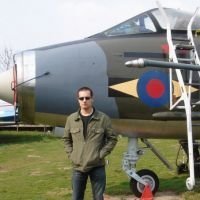
This is the Eurofighter from Revell's '60 Jahre Luftwaffe' set, but in its regular uniform without the festive decals. Thanks for looking! Luka
- 3 replies
-
- 29
-

-

-
- Eurofighter
- 1/72
- (and 1 more)
-
I am in the process of scratchbuilding the fire-fighting section for a Land Rover TACR1, using the Revell 1:35 kit as a basis. I have the main details for the side and rear, with the help from Mick Bell plans, but I am having difficulty working out how the top looks. I've done searches on dozens of images but they are mainly quarter-angled side views. Does anyone have top down photos and details of how the roof area looks please? cheers, Mike
-
Another older work of mine, but I think FGN (Federal German Navy) ships are a bit underrepresented. Hence ... As always: thanks for looking Cheers
- 14 replies
-
- 27
-
-
A little project to extend my pretty meager "rockets in 1/72" collection. The Revell Germany A4 plus a scratchbuild WAC As always: thanks for looking Cheers
-
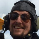
 Here is my latest build of a 1980s General Dynamics F-16 A Fighting Falcon of the Royal Netherlands Air Force. It is the J-257 of the 322 squadron based at Leeuwarden. Cheers!!!
- 12 replies
-
- 41
-
-
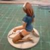
Another kit that I finished last year... I tried to change the shape of the cover over the helmet, but not really too succesful. Some little details added. I think the impression/atmosphere of the kit is quite good, accuracy is another issue As always, thanks for looking. Cheers P.S., yes I know Neil would have a hard time reading the checklist on his left arm. The watch is way too low - maybe I will change it - one day ....
-
Basically built this Starfighter for its striking experimental blue scheme. Thanks for watching Luka
-
Now I have finished my builds for another Gb I should have time for two or maybe 3 tanks in this one. First up is this. It is the simplified export version and comes with optional Iraqi markings. Pete
-
 Hi all, I've been here a few weeks now and though it was about time I showed you what I'm up to. I've very fond memories of watching Star Trek (TOS) as a kid in the 80's with my dad and my brother and it's one of the few things that has really stuck with me through changing times. The Enterprise itself I find mesmerising, it's graceful and each part of the ship has a clear purpose, a design classic and I love it. My favourite itteration has to be the refit, which I hope to build at some point in the future So, I got in to modelling because I wanted a decent model Enterprise, I've had a few very small die-cast models but they are always lacking something. I found the Revell kit online and decided that I'd build my own, LED lights and all. Now I've well and truly got the modelling bug, I've bought the Star Trek Starship Voyager for my next model, I've built a small Star Destroyer and plan to build models from Battlestar and other Star Trek models Here's some photos that I took while building my Enterprise, I wasnt originally planning on posting them online but then I found this place, so here it goes! 1. What a great start, I ruined my first model! I wanted to light my model with LEDs, so it had to be light-proofed. So the insides of the model had a coat of adhesion promoter, followed by black, then a silver or while coat would be painted to make it reflective. I was watching lots of Boyd's Trekworks Youtube videos for info and he used a heat gun on a gentle heat to aid the drying process.... I'll never do that again, my model melted You can see the plastic deformation from the heat in this image. It also shows my initial plan for lighting, which was to cover all windows with grease-proof paper, which diffuses the light, then placing LED's around the ship to light them up. 2. Saucer section interior is about ready So after buys a replacement model I started again, with a few important lessons learned This image shows the insides of the saucer section, painted and with the windows covered. I used 'Revell Contacta Liquid Special' to glue the clear windows in place, and to glue the greese-proof paper in place. The secondary hull, again with the inside prepared for lighting, it's had a black coat followed by a light coat to refelct the light. By this time I'd also started experimenting with LEDs, the breadboard in this photo had a 555 Timer chip and a 4017 Decade counter, they'll be used for the rotating lights of the Warp Nacells and the blinking navigation lights. 4.Let there be light! Not sure of the best positioning and arrangement of LEDs I just dove in with something that looked like it would give good coverage. I know some people use fewer but brighter LEDs, and some use LED tape/strips, which I might look at using in the future. Each LED has a resistor attached, and they're all in parallel, so if one should fail the others will continue to work. 5. Glue. After lighting the secondary hull in a similar way I was ready to glue a few parts together. Which I was pretty worried about as I considered it opportunity to ruin yet another model. I used Revel Contacta Professional glue and found my fears were unfounded, thankfully 6. Circuits To light this model I would need to build some circuits to handle the navigation lights and the rotating buzzard collector effects. So I bought the relevant gear from Maplin (I now use RS instead) and designed a few circuits in Pad2Pad, which is excellent free circuit design software. The first completed circuit was for the navigation lights, I was initially planning to put it inside the model but then decided I would fit it in the stand instead. 7. Warp Nacell Test #1 You saw my breadboard with a few components in an earlier photo. This is basically how the Buzzard Collector effect works on my model, The red, orange and green LEDs are aranged in a circle and give the impression of rotation. 8.Warp Nacell Circuit fitting After designing my Warp Nacell circuit in Pad2Pad, I printed it off, cut it out and placed it in it's intended final position to make sure it would fit. The circular plastic piece has holes drilled in it to receive the LEDs, 12 of them (for a single Nacell). 9. Assembled Warp Nacell Board After building the warp nacell board I fit it in place. Now you can also see how the LEDs sit. It's a pretty tight space so I was pleased that everything went in with no problems In the video below, the middle light isnt connected to any power, it will eventually be 'always-on' to provide a steady red glow. The camera doesnt really do the below any justice. 10. Closed up my first Warp Necell - and made my second big mistake It's amazing isnt it that you can do something, then the instant you finish you realise you've done it wrong. I guess it's not really that big a deal, the model isn't completely accurate anyway and I'd already decided that I would'nt worry about that this time. But this mistake was easily avoidably, yet at the crutial point I... put the wrong circuit in the wrong nacell, so the buzzard collectors now spin in the wrong direction. Only a Trek fan would notice, but it's annoying all the same. Still, after much grumpiness I think I can live with it. 11. Connecting the Pylons and the Seconday Hull. I'd already glued the warp nacells to the support pylons and let those set, I'd also done some work on removing the seams on all the parts glued so far. Now it was time to connect the wiring up and glue them to the secondary hull. With the wiring connected and the pylons glued on to the secondary hull, it looked like the area would be under a fair bit of stress, so I stuck a clamp in place to hold things together while they set. 12. Windows, I hate Windows I bought some masking fluid so that I could mask the windows, but found it to be far to imprecise and the results (of tests I did on my melted saucer section) were pretty messy. So after getting some advice right here on Britmodeller (thanks guys, you know who you are) I settled on masking the windows with masking tape. I used a scalpal to cut small rectangles working on one at a time. It took ages. I have used the masking fluid on a few of the larger clear pieces, but I'm still not impressed with the result, maybe I just need more practice with it! 13. All Masked, Time for the Primer With all the clear parts masked I bought myself a 'lazy suzan' and gave the entire ship a coat of Hycote Adhesion Promoter and then a nice coat of Hycote grey primer. No way was I going anywhere near this thing with a heat gun The wires you see here will eventually be fed through the stand in to the base. I found the Hycote cans give excellent fast coverage, pretty cheep too. 14. Base Color With the primer dry it was time to start mixing colours (as per the model instructions) and giving it some proper color. I used a 'Sparmax Arism Mini' Airbrush to spray the model, with Revel Aqua Color paints. I found that thinning the paint 2-parts paint to 1-part thinner worked pretty well. I'd aslo sprayed the deflector dish, I love that copper colour and started giving the warp nacell and impulse engines some colour. I was having trouble cutting the masking tape perfectly to cover the inside of the impulse engines, so decided to try the masking fluid. The result was not great but I think It'll look fine if I touch it up with a brush. So, that's my model so far. It's the first model I've ever build and while I've found it quite challenging I've really enjoyed it and plan to do many more in the future. I'll post more photos and videos as I make more progress. And thanks to everyone here for accepting me in to the site and giving me some great tips! Cheers
- 31 replies
-
- 15
-
-
My second entry will be this. It contains markings for 2 tanks both of which seem to be for the Gulf War(s) but gives no info as to location, date etc. The kit does not have the various "add-on" armour packages that later became a standard fitting I believe, particularly when used for urban fighting. Pete
-
This is the Revell re-boxing of the Preiser set, with some figures omitted.
-
 C-54D Skymaster (05652) 75th Anniversary Berliner Luftbrücke Airlift 1:72 Carrera Revell After the DC-3, Douglas began working on a design for group of major airline companies that was designated the DC-4, but it wasn’t quite to their liking, being less reliable and uneconomical than they would have liked, resulting in a design with a smaller airframe to meet their needs. War intervened, and the balance of the contract was taken up by the military under the name C-54 Skymaster, where it was used to transport cargo and personnel, with many variants with specific tasks such as Air Sea Rescue. The aircraft served throughout the war, and well into post-war through Korea, plus with many civilian operators, some of which flew into the 90s. There are still a few around at time of writing in museums and such. After the end of WWII and the former capital of Hitler’s Reich was split between the four main Allied powers, despite being located well behind the border of what became the Russian sector of Germany, which eventually became known as East Germany, or the German Democratic Republic. The Soviet Union quickly transitioned from Allies to enemy due to mutual distrust, which signified the beginning of the Cold War that dragged on until the early 90s. A land corridor was used by the Western Allies to supply their sector of Berlin, but this was blockaded by the Soviets in the summer of 1948, who generously offered to remove it if the Allies withdrew the newly introduced Deutschmark from the Allied occupied sectors. The Allies weren’t willing to give in to their demands however, and plans were made to supply Berlin by air, in the hope that the Soviets wouldn’t dare shoot down unarmed transport aircraft. They were right, and for the next fifteen months, the seemingly impossible task of supplying the city was accomplished by the Allies, with the C-54 involved, with around 330 airframes taking part. The airlift wasn’t without cost however, and over 100 pilots and crew died in accidents relating to operation of the airlift, several of them crews of Skymasters. The success of the operation became more embarrassing for the Soviets as the months rolled by, and eventually they lifted the blockade of their own volition, but the Allies carried on supply by air for some time after, in case the Soviets had it in mind to reestablish it, which had extended to road, rail and even canal transport. Berliners were extremely grateful, and there remains a Historical Foundation that maintains a museum to commemorate the actions of their former enemies, and they have a C-54 as one of their exhibits. The Kit To remember the 75th anniversary of the airlift, Revell have re-released their 2016 tooling of the C- 54D in a new box that includes four paints, a bottle of Contacta Professional glue and a #2 paint brush, plus a small bag of ten laser-cut plywood boxes to act as cargo for the model, all enclosed in a vastly over-sized top-opening box. There are also fourteen sprues of light grey styrene, a clear sprue, large decal sheet and the instruction booklet, which is printed in colour and has painting and decaling profiles on the rear pages. This is a modern tooling, and has plenty of detail in the cockpit, interior and gear bays, although the flying surfaces are joined to the airframe with T-shaped hinges that seem to be a throwback to an earlier time when models were also intended as play-things. If left mobile, drooping ailerons on both sides would be indicative of a control failure, so it might be a good idea to apply a little glue to freeze the controls in a manner to your liking. Construction begins with the nose gear bay for a change, building the two sides on the roof panel, which is also the floor of the cockpit, flipping it over to install the instrument panel with moulded-in centre console and a forward bulkhead, applying a decal to the panel after painting. A detail insert finishes off the console with moulded in throttle quadrants and other controls, plus a triangular coaming that joins the panel and bulkhead together. Both pilots get an L-shaped control column with separate yoke, handed toward the centre, and a trim wheel on each side of the central console, then their seats are made from two-part seat cushions with moulded-in four-point harnesses, while the third crew member has lap belts only. The pilots’ seats are then mounted on a two-part frame and fitted to the rails moulded into the cockpit floor, painting everything as you go. A bulkhead with a doorway is detailed with five parts and has two decals to add detail, then it is mounted on the front of the passenger/load compartment floor, which has some nice detail moulded into its surface. The bulkhead for the rear of the radio/engineering compartment is also detailed with four parts plus the third seat, and is fixed into the slot in the floor to create the space, with a scrap diagram showing how the detail parts should link to two bulkheads together. More detail is added in the shape of a short corridor and section of wall to deepen the bulkhead on both sides, one of which has a fire extinguisher moulded-in. Two cots insert into the right side of the bulkhead on tabs, and are locked in place at the other end by another bulkhead with separate door that can be posed open or closed, adding a roof section over the top between the bulkheads. Two runs of five canvas and webbing seats are made from two parts each, and placed in the load area just behind the bulkheads, enclosing the space with two inserts that have tons of ribbing detail moulded into them, with the option to cut out the side load door, which is marked out on the outside of the part. The rear bulkhead is stepped and closes the rear of the fuselage interior, and the cockpit with nose gear bay is glued to the front bulkhead, completing most of the work on the interior details. The nose gear strut is a complex affair made from seven parts and is inserted into the bay, the drawing for which has one wall rendered invisible to aid location of the assembly. The fuselage halves are fitted with portholes on a long clear carrier, painting the cockpit area in green, then detail-painting the equipment boxes and cutting out the half-circles over the cockpit that will later receive an astrodome. A set of flashed-over holes under the belly are also opened at this stage, and you have the option of posing the crew hatch open on the starboard side of the nose, then repeating the process on the port fuselage half, which has a few more individual portholes. The interior is glued into the starboard fuselage half, and you are instructed to add 60g of weight into the spaces in and around the nose where it won’t be seen, then a pair of curved spacers are mounted under the main floor, and an insert is put in place where the side cargo door is located. The fuselage can then be closed, at which point you realise this is quite a large model, even at 1:72. The lower wings are long and slender, and are moulded as a full-span part, with the main gear bays moulded into the inner engine nacelles, painting the interior in green, and removing the short length of sprue that supports the part during moulding and transport. Each of the four nacelles are closed at the front by circular engine mounts, being careful to arrange them correctly so that the exhaust outlets are on the outer sides. The inner nacelles have bulkheads inserted behind the new parts, fitting another to the rear of the bays, and inserting a roof segment into the rear, all of which is painted in interior green. The flaps can be posed deployed, or “cleaned-up” for flight, and if you wish to deploy them, you will need to remove the portions marked in grey on the lower wing, as per the accompanying diagram, inserting flap bay wall inserts into the space, then closing the wings with two upper halves. The prominent intakes and their fairings on the top of each nacelle are each built from front and rear parts, and glued into recesses moulded into the upper nacelles, then the wings can be mated to the fuselage, adding inserts onto the nacelle sides for the exhausts. The flap bays are extended by adding an insert with the flap mechanism, fitting another inboard after removing a small portion of the base on both sides. The rudder fin is moulded to the fuselage, and has two T-shaped hinge-points moulded-in, onto which the two rudder panel sides are glued, giving the option of leaving the rudder mobile. The elevator fins are each made from two halves, and slot into the tail, with the flying surfaces glued around them in the same manner as the rudder. The intakes under the nacelles are completed with a lip, and an outlet at the rear, fitting the exhaust collector rings around the nacelle bulkhead for each of the four engines, which are next on the menu. The rear bank of pistons have a two-part push-rods and intakes added to the rear, trapping the axle between the two portions, with the front bank glued in place after sliding it over the axle, and finishing off the motor with the bulkhead, magnetos and push-rods moulded as one part. With all four engines complete, the cowlings are made from the cylindrical section that is moulded as one part, plus a choice of open or closed cooling gills at the rear. The engines slot into position in the cowlings on guides, and a scrap diagram shows the correct location. The assemblies are then glued to the nacelles on T-shaped pegs that match recesses on the firewall bulkhead, and they are completed by adding a choice of two styles of exhausts into the exit holes. It's not made abundantly clear to the hard-of-thinking (aka me) that the gear can be depicted raised for flight, so it’s good to know in advance to save you from gluing the nose gear into position before you get to the steps that deal with the landing gear. The nose wheel is made up first, and there are three styles, one for each of the decal options, as shown by the instruction steps that are mentioned at the bottom of each diagram. Two types are made from two halves, while the third is built from two halves plus a centre insert that will be seen through the spokes. To build a model with gear up, the nose bay is covered with a single lozenge-shaped door part with an engraved panel line down the centre, while the gear down option requires them to be cut in half down the panel line. Your choice of nose gear wheel is flex-fitted between the halves of the yokes, so can remain mobile, unless you intend to file a flat-spot to portray the weight of the airframe, in which case a dab of glue will suffice to keep it in position. The main gear legs are built from the strut and a chunky Y-shaped retraction jack, that has three additional parts linked to the upper portion, adding hubs to the cross-axle at the bottom end, which differ depending on which set of wheels you are using, as there are three again. Before installing them, a separate scissor-link is fitted to recesses in the front of the strut, then the three types of wheels are built, one with a separate hub that is inserted into one side of the two-part wheel, the other two made from halves, with a small hub cap on the outer face. In addition, there are twin brake hoses fitted to the front of the struts, with one end fitting into recesses in the hubs, adding a small triangular part between them, and a Y-shaped strut into the bay, plus a small antenna under the nacelle. Two actuators are added either side of the main wheel strut, and these open and close the main bay doors, which are cut from the single part that is used for the in-flight option. The remainder of the bay door part is also cut into three, and two mount on studs at the base of the strut, and the other at the front. For the gear-up option, the bay door part is used without cutting and is simply glued into the cut-out. Back to the flaps. To lower the flaps, two parts per wing are glued together, and mounted on the actuators that were installed earlier. To model them retracted, two alternative parts are glued per wing and inserted flush, in line with the airflow. In a small diagram the tail receives a light at the top of the fin, adding another two in a fairing that is glued to the pen-nib fairing at the rear of the fuselage. At the other end of the fuselage, the canopy part has an overhead console glued into its roof and painted according to the diagram before the canopy is glued down, joined by an astrodome behind it, a pair of twin antennae on an insert in the roof, and a small intake off to one side. Under the wings, a pair of pop-up landing lights are inserted into a recess either flush with the skin of the wing by cutting off the peg, or folded down on the peg. The cargo door is moulded as a single part that can be cut to depict the doors open, and a small porthole is inserted into a hole in the narrower door. Whether you pose them open or closed is up to you, but open doors in flight might whistle a little bit. Fitting the antenna and props are the last thing you’ll be doing after main painting, and on this kit the three-bladed props and spinner are moulded as a single part, and each one slots onto the axle projecting from the front of the engine. A cluster of probes and antennae are fitted around the nose, under the nose, under the wing roots and under the aft fuselage, after which there are two diagrams that show where the antenna wires should be fitted, using your favourite rigging material to finish the task. Just in case you didn’t put enough weight in the nose, Revell have thoughtfully supplied a stand that can be placed under the tail to prevent the crew from ending up in the tail. Markings There are four decal options on the large decal sheet, all wearing the same silver scheme, but with different markings to tell them apart, in addition to the wheels of course. From the box you can build one of the following: Air Transport Command, Airlift Berlin, 1948 USAF, Airlift Berlin, 1948 US Navy, Airlift Berlin, 1948 USAF, Airlift Berlin, Wiesbaden Air Base, Winter 1948-49 Decals are by Cartograf, which is a guarantee of good registration, sharpness and colour density, with a thin satin carrier film cut close to the printed areas. Conclusion A well-detailed model of this common transport from WWII and the Cold War, depicted as four airframes that participated in one of the most ambitious, extended and successful airlift missions in all of aviation’s history. It would make a great memorial to all the pilots and crew that lost their lives helping the people of Berlin survive. Highly recommended. Carrera Revell model kits are available from all good toy and model retailers. For further information visit or
 -
Hi all! Here is my latest production, it is actually a very old kit from the 1990s. The Dragon kit of the Dornier Do 335 has been revived several times in recent years: by Revell and lately by Hobby 2000 but the kit is always the same. A kit with a very fine detail and well made but with a quite complicated construction. The Revell kit also has unclear instructions and horrible decals! As always i used a set of mask and a PE sheet from Eduard and Gunze Mr Hobby Colors. Hope you'll like it!
- 23 replies
-
- 68
-
-
-
Hello everyone, I live about a 10 minute car ride from the Möhne dam, so naturally I had to build a dambuster. I did, about 15 years ago, the Revell one (others hard to get here). Not the newer version that happened to turn up in stores a few months after, but the decade-old animal with no interior (just like with my B-17). I did some upgrading, without any AM parts but strickly selfmade. Well, almost, I got a spare pilot seat from my pal who had a new "normal" Lanc, and I peeked into his instructions for building an interior. The crew was on board, although the only visible thing of the radioman was a piece of yellow lifvest through the window. After that, I moved several times, and the model disappeared in a box. About 2 weeks ago, I got to, well, upgrade my show-cupboard, suddenly had lots of empty room, and while looking for things to place there stumbeled upon the Lancaster. By accident I got the idea for a display... and here it is. A plank with half a plastic chopstick. Horribly silvered decals. So be it. No time to upgrade, didn't want to wait half a year for the full anniversary. ) No, you haven't had a pint too many... one focus on the pilot and flight engineer, the other on the maps of the navigator. The cockpit hood (is that correct with such a big thing?) had come loose during storage, and in an unfortunate accident the radioman went AWOL. I got him of course, but there's no way to get him sit at his post again. I decided to do Gibson's plane. Starting with the wooden stand, I wasn't sure if I had a good idea or if it'd turn out absolutely hideous. Actually, I'm rather pleased with it. What do you think? RRRROOOAAAAARRRRing across the water towards the dam... That's all (for now, might redo some things, like the prop discs), Johnny Tip out. (No mention of the codeword for success? ... No.)
-
 Talk softly and carry a big gun. Here's my latest completion, the Revell (ex-Dragon) Bf110C, with the AIMS conversion set used to modify it into the C-6 version with the 30mm MK.101 cannon and marked as one of the aircraft used by Erprobungsgruppe 210 in the summer of 1940. To the base kit and conversion were added the Quickboost exhausts, Red Fox Studios 3D instruments and radio gear fronts,the HGW seatbelts and interior/exterior mask set and LF models mask for the camouflage pattern. Revell re-jigged the Dragon instruction sheet which made it easier to follow but included quite a few errors, omissions and just-plain-headscratching assembly choices; I did my best with it and deviated where I thought it prudent and I pretty much got away with it I think. I found building the kit to be absorbing, at times a bit frustrating, but overall I enjoyed it to the extent that I have started on a second one, and now have a third in the stash (the Hobby 2000 Bf110D). Mistakes were made. Some of my work was down to its usual shonky standard and the camouflage pattern on the port side is just wrong, I made the mistake of thinking it would be possible to fit the wings right at the end and only realised then that I had obviously misplaced some of the camouflage masks. Still, in the end I got it finished and that's a long-awaited one off my 1/32 bucket list. Paints were Colourcoats ACLW12 - RLM Grau (RLM 02) for the interiors, ACLW03 - Hellblau (RLM 65) for the undersides and the top surface camo was ACLW02 – Schwarzgrun and ACLW11 - Dunkelgrun (RLM71). The blue on the prop spinners was a mix of Citadel acrylic blues mixed as close as I could to the blue on the aircraft code letter. Oh yes, one more for scale: Cheers, Stew
 -
Dornier Do.217J-1/2 (03814) 1:48 Carrera Revell The origin of the Do.217 was the Do.17 ‘Flying Pencil’ as it was colloquially known, in an effort to extract more power and therefore speed from the engines, extend its range and give it a better bomb load amongst other improvements. The resulting airframe was a capable and left the early war designs in its wake, becoming known as a heavy bomber in Luftwaffe service, something they were very short of throughout the war. It was also a versatile aircraft in a similar way to the Ju.88, and was adapted to many other roles like its predecessors, including the night fighter role, to which it was suited, although not initially. Various engine types were used through the endless rounds of improvements, with radial and inline engines fitted in a seemingly random pattern throughout the aircraft's life. The first night fighter was the J-1 with radial engines that had a crew of three in an enlarged cockpit and solid nose sporting four MG17 machine guns and another four 20mm cannons in the front of the gondola for concentrated forward fire. The crews disliked it due to the increased weight of the extra equipment however, and criticism led to an order to cease production of the night fighter variants, which Dornier either didn't receive or chose to ignore. The J-2 was little better, changing the 20mm FF/M cannons out for MG151s and removing the vestigial aft bomb bay, which was faired over with an appropriate drop in overall weight. Some of this weight was gained back with the installation of the FuG 202 Lichtenstein radar. This still wasn’t enough and the crews continued complaining, leading Dornier to produce the improved N series, which eventually entered service in small numbers as the N-1 and N-2 variants. The Kit This is a reboxing by Revell of minor tooling revision from ICM, based upon the sprues from the J series’ successor, the N series that was tooled first. The additional sprues cover parts for the backdating of the engines and nacelles to the earlier BMW 801 radials, as well as a new nose cone and cover for the radar equipped J-2 and earlier J-1 with its clean radar-free nose. Inside the large end-opening box are nine sprues in grey styrene, although the instructions show the two wings on separate sprues, but these are linked in our sample. A clear sprue, sheet of decals and the instruction booklet complete the package, most of which is held in a resealable clear bag, with the decals inserted within the pages of the instruction booklet. Construction begins with the well-detailed cockpit and fuselage, which is almost identical to the earlier N until you reach the nose cone, giving you a choice of the unadorned J-1 nose with cover for the tip where previous variants had searchlights, or the similar J-2 nose that has a pair of supports for the radar whiskers. The wings and tail are also identical to the N, although the new engines and nacelles are where things start to diverge properly. The radial BMW units are made up from two banks of pistons, the rear set having a bulkhead moulded in, then has the ancillaries and cooling fan added to the front. The cowlings are built in sections with exhaust stubs fitted to the insides, with three sections linked to complete the cylindrical cowling into which the engine slots before being locked in by the front cowling lip. This of course is done twice, as are the nacelles, which have ribbing detail moulded within and bulkheads to add detail and prevent see-through issues. The engine cowling slots onto the front of the nacelle and the retraction jacks are installed from above before it is fitted to the wing, as are the main oleos, mudguards and the two-piece wheels. You can also add in the gear bay doors at this point if you’re a masochist, or leave them off until main painting is over. The underside is completed by adding in the engine nacelles, completing the rear of the gondola under the nose with its glazing and inserting the closed bomb bay doors for the J-1, or by leaving the bay open, adding the extra fuel tank that was used to extend range, and installing the bifold doors in the open position. The retractable rear wheel also has its doors fitted with a small insert in front of the bay, finishing off the area. Flipping the model over shows the open cockpit, which needs the remaining parts adding before the glazing can be glued in place. Some small parts are added to the inside of the canopy before it is put in place, with the rear turret and defence machine gun added into the rear fairing. Additional appliqué armoured glass is present on the two front canopy panels, which can be “glued” with some clear varnish, making certain you haven’t trapped any bubbles between the parts before you set it to one side to dry. The next steps involve guns. Lots of them. All the barrels are slotted into the nose and your choice of nose cap is fitted, with the radar whiskers made up and cut to size for the J-2 decal options. The props are made up from a single part with all blades moulded in, then trapped between the front and rear parts of the spinner. The last parts are a set of cheek “pouches” that are fixed to either side of each nacelle with a set of curved grilles moulded in, and two exhaust deflectors on the top of the nacelles. Markings There are two decal options included on the sheet, both wearing a green/grey splinter over blue undersides, and differentiated by their markings and mottle patterns. From the box you can build one of the following: Do.217J-2, II./NJG101, Luftwaffe, Hungary, 1943 Do.217J-1, II./NJG1, Luftwaffe, 1944 Decals are by Cartograf, which is a guarantee of good registration, sharpness and colour density, with a thin matt carrier film cut close to the printed areas. Conclusion The Flying Pencil and its variants don’t get as much love as the more popular Junkers or ‘einkels, but they played an important part in the Nazi war machine, so deserve the level of effort that has clearly gone into production of this kit. Highly recommended. Carrera Revell model kits are available from all good toy and model retailers. For further information visit or
-
Messerschmitt Bf.109G-6 Easy-Click System (03653) 1:32 Carrera Revell With almost 34,000 examples constructed over a 10-year period, the Messerschmitt Bf.109 is one of the most widely produced aircraft in history and it saw active service in every theatre in which German armed forces were engaged. Designed in the mid-1930s, the Bf.109 shared a similar configuration to the Spitfire, deploying monocoque construction and V12 engine, albeit an inverted V with fuel injection rather than a carburettor as used in the Spit. Initially designed as a lightweight interceptor, like many German types during WWII, the Bf.109 evolved beyond its original brief into a bomber escort, fighter bomber, night fighter, ground-attack and reconnaissance platform. The Bf.109G series, colloquially known as the Gustav, was first produced in 1942. The airframe and wing were extensively modified to accommodate a more powerful engine, greater internal fuel capacity and additional armour. In contrast to early 109s, which were powered by engines delivering less than 700hp, some of the later Gustavs could output almost 2000hp with water injection and high-performance superchargers. The Gustav series accounted for a dizzying array of sub-variants, some of which featured a larger tail of wooden construction. Odd number suffixed aircraft had pressurised cockpits for high altitude operation, Erla Haube clear view canopy with clear rear head armour, underwing points for tanks, cannon or rockets and larger main wheels resulting in square fairings on the inner upper wings to accommodate them. The Kit This is a new tooling from Carrera Revell, but it isn’t a traditional plastic model kit, instead it is one of their Easy-Click system, but unlike any that we have seen previously, as it snaps together in a manner similar to the famous Lego bricks. The kit arrives in a standard end-opening box with a render of the finished product on the front, and inside are five sprues of parts, one grey, one green, two light blue, and one black, each one ready to clip together once cut from the sprue. There is also a clear sprue with a single canopy part, a sheet of decals, a sheet of stickers, and the instruction booklet that is printed in colour and has decaling and sticker application guides on the rear. Each part joins to the other by friction fit, and each location turret has a corresponding circular receiver, and here an issue has crept in that might concern a “serious” modeller, as some of the receivers have resulted in shallow sink marks in the self-coloured plastic, which is most evident on the green coloured plastic. I suspect that we’re not the intended audience however, as this is an ideal method of introducing modelling to a younger person, removing paint and glue from the equation, but keeping the cutting of parts from the sprues, and giving them a choice of decals or stickers, depending on their skill level or impatience. Construction begins with the main landing gear, which are made up from two parts including the wheel, and can be lowered or retracted thanks to a short axle at the top of the legs. They are placed in the lower wing halves, and each wing is fitted to a central black former that has some of the cockpit detail moulded-in, including the control column. The wing roots are added, with optional painting instructions for the more advanced modeller, fitting the seat back into the cockpit, then surrounding it by two cockpit sides. The exhaust stubs are fixed to the front of the central former, and is surrounded by cowling parts on both sides and under the chin, adding another panel under the wings, hiding the central former. The instrument panel has two decals to apply, and this is inserted into the front of the cockpit, fixing the supercharger intake on the port side of the fuselage, then fitting the upper cowling gun troughs, the black barrel insert, and the rear cowling in front of the cockpit. The upper wing parts are then clipped into place in green and grey to create the splinter camouflage out to the rounded tips of the wings, trapping the gear legs in position at the same time. The starboard side of the rear fuselage is clipped into position on the central former, then a black extension is added, and locked in place by the port rear fuselage side, pausing to clip the canopy into the upper fuselage part, which has recesses to accept the moulded-in framework, which has caused a little distortion of the clear parts. The centre former is extended again with a short part that includes the tail wheel, closed in by more tapering fuselage sections, then adding a short length of spine in green, and the tail fin on both sides of the centre, filling in the rest of the spine and slotting the elevators into a groove in the tail fin, then finishing off with the rudder. To complete the model, the three-bladed prop is clipped onto the axle, and a spinner tip completes the prop. Underneath, a two-part drop-tank plugs into a two-hole recess after clipping the two halves together. Markings There is one scheme in the box, but as there are decals and stickers included, the process is shown twice, as the numbers differ between the sheets. Even though this is an Easy-Click kit, there is still a good number of stencils and other markings, so your model will have plenty of visual interest once completed. From the box you can build the following: The decals are by Cartograf, which is a guarantee of good registration, sharpness and colour density, with a thin satin carrier film cut close to the printed areas. Conclusion This kind of kit is a great introduction to modelling for today’s impatient youth, who probably wouldn’t even notice the slight sink marks on some parts. Recommended. Carrera Revell model kits are available from all good toy and model retailers. For further information visit or
-
Unless we get an extension I am not going to finish this, and even if we do I expect it will end up in the KUTA, but what the heck!😄 I have been wanting to replace my ancient Frog model, and judging by the reviews in the GB, this reboxing of the Cyber Hobby kit is not bad if you ignore the ridiculously undersized ejection seats, which I may be able to fix, and the incorrect nose shape. Fortunately I bought a resin replacement nose a few years back when I was considering buying the Xtrakit version. Pete
-
 Hi All Usual reluctance to post anything in this fabulous forum! Nothing special just the 2001 RoG boxing of the near 50-year old Revell B-17G OOB with Tamiya Fuel Truck & ICM Bomber crew. Thanks for looking and see you at Telford! Best Regards Ben
- 23 replies
-
- 71
-
-
-

-
’66 Shelby GT 350R (07716) 1:24 Carrera Revell Ford’s Pony Car was first introduced in 1964, and immediately struck a chord with the American car-buying public, claiming a place in motoring history as it did so. By 1966, not much had changed yet, including the size and weight of the car, making it one of the lightest from the whole lineage. The Shelby 350 was a modified Mustang, with more powerful engine, stiffer suspension and distinctive styling in any colour as long as it was white, making it a track-style car before that name was fashionable, also changing the name to capitalise on the reputation of the Shelby company. The first batch of the ’66 350s were based upon the Fastback chassis, and colours other than white were available, and over 1,300 were made, plus around 1,000 in the standard bodyshell. A small number of ‘special’ cars were given the R suffix to differentiate, as they were race-prepared, and not suitable for picking up a carton of milk and a pack of Lucky Strikes from the local 7-Eleven. These cars raced in the SCCA (Sports Car Club of America) Pro Racing series, including races at Laguna Seca and Riverside tracks. The Kit This is a reboxing with new decals of the 1985 tooling by Revell under the Monogram branding, which is backed up by the raised lettering on the underside of the interior tub of the model. The kit arrives in a shallow end-opening box, and inside are four sprues and the bodyshell in white styrene, another sprue that has been chrome-plated over white styrene, a small clear sprue, decal sheet, and instruction booklet that is printed in colour with profiles for the decal option to the rear. This is a special boxing that depicts a single car as it raced on two tracks with Walt Hane at the wheel on both occasions. This is an old kit, but has good detail, and time has been kind to the moulds, including a full engine, underside details and the spartan interior that had been stripped down in anticipation of racing. Construction begins with the engine, two parts for the block and transmission halves, adding multi-part detail inserts top and bottom, then fitting two cylinder-blocks and their rocker-covers, which have decals for the top, then accessorising it with alternator, serpentine belt, fan and manifolds, exhausting four cylinders per bank. The under-tray of the vehicle is then outfitted with the front axle with suspension moulded-in, twin sports exhausts that exit at the sides in front of the rear wheels, and the rear axle, which has ‘hi-tech’ leaf-springs and the drive-shaft moulded-in, then has a pair of dampers fixed between them and the chassis to reduce rebound, installing the engine between the chassis rails at the front, joining the down-pipes from the manifolds to the exhausts. The interior is begun by applying six dial decals to the instrument binnacle, and a further two to the smaller central binnacle, taking the time to remove the standard equipment details in the centre of the main dashboard, as no-one listens to music while they’re racing. The two binnacles are glued into position, fitting the steering column with stalks, and spacing the lightened steering wheel with a tapering extension, then the instructions have you switching to the other wheels, inserting the two hub sides from each side of the flexible black tyres, applying gold or white Firestone logos to them depending on which race you are modelling. After that diversion, the dash is inserted into the front of the interior tub on a pair of notches, and the angled gear shifter is fixed to the transmission tunnel before the rear seats are covered over by a blanking plate and two flashed-over holes are drilled in the flat area at the rear of the doors for later use. The solitary driver’s seat and a covered spare tyre are put in place behind the wheel and on the blanking plate at the rear respectively, and a three-part roll-cage is located on the two holes, and that has a fire-extinguisher moulded into one of the cross bars. The bodyshell is prepared by painting the roof liner dark grey and sanding away the logo moulded into the front arches, then the front and rear screens are popped in from within, adding a chromed rear-view mirror into a hole in the top of the windscreen, before the rear quarter-light cut-outs are covered over with blanking panels that are painted red. Another small moulded-in logo is removed from in front of the arch, although that would have been better done at the same time as the other, then the interior tub is glued into the shell, painting portions of the underside red, as some of it will be seen through the floor pan once the assemblies are joined. Before that however, the rear light clusters are painted as per the instructions and fitted on pegs into the rear of the car, then the chassis and bodywork are brought together, adding a pair of coil-over shocks in the front turrets, which you can paint red if you have steady hands. The wheels are snapped onto the axles in each corner, then the engine bay is painted black around the engine, so it is probably a good idea to paint that before you have the engine in the way, for the sake of your sanity. A dash pot is glued to the firewall, and a strut brace is fixed to the suspension turrets, then the interior front bulkhead with separate radiator is slotted into the front of the bay, jumping back (literally) to add the rear bumper and opener/badge in the centre of the boot. We’re back at the front to install the bumper and chromed radiator, adding chromed reflectors with clear lenses in front that have a fine mesh texture engraved on the rear. Two circular chrome side-lights are painted orange and inserted into the corners of the bumpers to complete the car’s distinctive ‘face’. The bonnet has some detail moulded into the underside, but you’ll need to remove the ejector-pin marks in between them, applying the two go-faster stripes after painting, and another decal that depicts a circular mesh vent over the stripes toward the rear. The air-box and radiator feeder-pipe are glued into the engine bay, and the bonnet can be slipped into position without glue to leave it mobile, adding a chromed stay that is supplied to prop it open, or you can lay it across the bay, dropping into two recesses in the bonnet sides. There are some additional decals applied in the bay, some to bulkheads, others for the ancillary parts that gives the area a little extra realism. Markings This is a special edition in all but name, as it has decals for two particular races that this car took part in, one at Riverside, the other at the world-famous Laguna Seca circuit, and while you’d expect the car to be almost identical for each race, you’d be mistaken, as there are some subtle differences, such as the colour of the Firestone logos and the colour of the driver names. There are also two styles of pony logo on the front grille, one with silver trim, the other with just the coloured stripes and the outline of the horse. Decals are by Cartograf, which is a guarantee of good registration, sharpness and colour density, with a thin gloss carrier film cut close to the printed areas. Although the decal numbers are called out for the seatbelts on the instructions, they aren’t represented in the drawings, so in case you missed it, there is a full set of seatbelt decals to add extra detail. Conclusion This is an old kit, but other than the lack of outer runners and the copyright details giving it away, it’s not what you’d expect. There’s plenty of detail, and the body is well shaped. The instructions are a little odd in places the way they flit around, but taking some time to look them over should help avoid mistakes. Highly recommended. Carrera Revell model kits are available from all good toy and model retailers. For further information visit or
-
Hawker Hurricane Mk.IIB (04968) 1:32 Carrera Revell Although somewhat less glamorous than the Supermarine Spitfire in the eyes of some, it was the Hawker Hurricane that proved to be at least half of the backbone of Britain’s air defences during the summer of 1940. Designed in 1935, the Hurricane was relatively advanced compared to other fighters in service at that time, featuring a fully enclosed cockpit, retractable undercarriage, eight .303 inch machine guns, a powerful liquid-cooled V12 engine and, most importantly, a cantilever monoplane. Despite its modern appearance however, the design and manufacturing techniques were thoroughly conventional, which meant that it was relatively straight forward to produce in large numbers. This proved useful when it came to manufacture because the aircraft could be churned out quickly, and was easy to repair and maintain. The Hurricane's first kill was achieved on 21st October 1939 when 46 Sqn found and attacked a squadron of Heinkel He.115s over the North Sea. The Mk.I was initially fitted with fabric-covered wings, which limited its dive speed, which was rectified by the replacement with a more robust metal skin, and adding a stabilising strake beneath the rudder to assist with spin recovery. Armour protection for the pilot and self-sealing fuel tanks were also added in light of combat experience, making the aircraft more survivable for the pilot, and increasing its ruggedness. The Mk.II was equipped with the Rolls Royce Merlin XX engine, capable of developing almost 1,500hp with the help of a two-speed supercharger and revised glycol/water injection system. The longer cowling required by the new engine also improved stability further, and by the time the Mk.IIB was in production, it also had hard-points for carrying bombs or additional fuel for longer-range sorties. Although the Hurricane was a solid performer, it proved to have less scope for improvement when compared to the Spitfire, and as it was slower due to its aerodynamics, the Spitfire became the poster-child of the Battle of Britain and beyond, despite the Hurricane claiming more kills than the graceful Spitfire. Later variants were fitted with 20mm cannons, and the final production variant, the Mk.IV used the so-called ‘universal wing’ that could carry bombs, weapons, fuel and other options, with a deeper armoured radiator housing under the centre. The Kit This is a brand-new tooling from Revell, and has been anticipated by many larger-scale WWII modellers since its announcement. The bated breath should now have been released and some mouthwash slooshed, as it’s available now from all the usual places online and in the real world. It arrives in a deep end-opening box, and inside are eight sprues in light grey styrene in three bags, a separately bagged clear sprue, a decal sheet secreted inside a colour instruction booklet that has markings profiles on the back pages, and a list of paint choices in Revell codes near the front. Detail throughout is crisp and neat, with finely engraved panel lines and relief for the fabric-covered areas that do a good job of representing the skin of the real thing. There are a lot of ejector pin marks inside the fuselage halves, and a few of them encroach upon the sidewall details of the cockpit, although whether they’ll be seen is debatable. Construction begins with the cockpit, which is made from sub-assemblies, starting with the pilot’s seat, which is fabricated from base, back and two side panels, then the bulkhead behind the pilot is layered from four sections after drilling some holes in the tapered top-section. The foot troughs and framework are joined together, and the sidewall framework is detailed with small parts, predominantly on the port side, and a cross-member with framework and hose is assembled. There is a lot of detail-painting called out with coloured flags with letters that cross-refer to the paint guide at the front, and this continues throughout the whole build. The framework of the cockpit can then be joined together by adding the cross-member and a tubular A-frame, with the front slotting into four holes in the forward bulkhead. The ‘floor’ of the cockpit is inserted into the assembly and rotated into position, after which the control column and linkage is installed along with the rudder pedals between the two troughs. A compass with decal is dropped onto a mount near the front of the cockpit, and in the rear the armoured bulkhead is slid down into the framework at an angle so that the seat can be fitted, with a scrap diagram showing the correct location from the side. A long winding hose is inserted down the port side of the cockpit, with the rear end curling round and mating with the cross-member under the seat, and there is another scrap diagram to help you with this. A lever is inserted into a socket in the starboard side behind the armour, with the handle projecting into the cockpit, which brings us to the instrument panel, which is surfaced with raised and recessed detail, over which you apply three decals for the various sections before gluing in place between the two sides of the cockpit framework. A choice of oval or rectangular lensed gunsight are added to an angled mount that slips through a hole in the panel in front of the pilot. In order to close up the fuselage, the spacer that fills the area where the Merlin should fit is joined together, and this has exhaust ports moulded-in with good detail, and the two halves trap the axle in place, along with the front detail insert that depicts part of the motor. This and the cockpit assembly are added to the starboard fuselage half after it has been painted internally, the afore mentioned ejector-pin marks dealt with if you feel the need, and the addition of a small detail skin to the aft of the sidewall. The port fuselage half is painted and has a detail part fixed into a socket, then the two halves are brought together, and here the instructions advise not to glue the cockpit framework into either fuselage half, but leave it floating in the sockets, presumably to achieve a better fit. The top of the engine cowling is glued over the empty space, and the closed canopy is temporarily taped into position over the cockpit opening for reasons that aren’t expounded upon. The main gear bays are actually a single space beneath the two bay openings, and are made up in stages, starting with the leading edge, which has two ribs attached to the main shape, then has a clear roof insert added, which is clear to replicate the two observation windows there, and they have a hose snaking across front to back. Some small detail parts are inserted, followed by the rear bulkhead, which has a two-part cylinder attached to the middle, and two retraction jacks glued to the sides. The wing’s centre section is separate on this model, and has a spar fitted inside, locating on pins that are moulded onto the inside, then the bay assembly is pushed into position, feeding the hose through a hole in the spar until it locates on more pins. Both lower wing halves have a cut-out in the leading edge that receives a landing light bay that has a separate lens slotted in before it put in position, painting the inside interior green. They are both glued onto the centre section using pins and tabs, and are closed over by adding the upper wing sections, drilling a hole in the starboard part if the aircraft had a gun camera mounted. Flipping the wing over, the leading edge of the centre section is added, then the remaining inserts that include the gun ports, clear landing light cover and other small parts such as the gun camera shroud are inserted along with the clear wingtip light covers. The fuselage is dropped into position between the wings, and underneath the chin insert and lower fuselage insert are fitted, followed my a recognition light and the fairing around the tail wheel. The trailing edge of the strake in front of the tail wheel is then sanded to a new angle by removing 2mm from the bottom and nothing from the top. The chin intake is put together from top and bottom halves, and the radiator core is made up from front and rear sections, and dropped into the cowling, which is built from an oval intake and the streamlined fairing, and once installed under the wing it has the flap at the rear added in the open or closed positions, using the diagrams to the side as guidance. All the flying surfaces are separate, so can be depicted at any reasonable angle, starting with the rudder panel, which is made from two halves and has a clear lens fitted above the trim-tab. The elevators fins and panels are all similarly two parts each, and fit to the fuselage under the fin via the usual slot and tab system. The ailerons are dealt with later, and are again two halves each, slotting into the spaces in the trailing edges, then you can choose whether to depict the flaps in the open or closed positions by swapping out the parts as per the instructions. There are ribs moulded into the open flaps, but the flap bays are devoid of any detail. The front of the fuselage has a fairing added to the front, with a choice of styles, one of which is open at the front, the other partially closed by a cover. There is a choice of two styles of exhaust, one with round pipes, the other with fish-tail outlets, and are each made from two halves, although they don’t have open ends. This could be remedied by opening the tips before joining the halves, taking care to cut them to the same profile as the exhausts. When finished your chosen style assembly is slotted into the outlets in the side of the cowling and painted a suitably hot and grimy colour. The crew stirrup can be depicted dropped for access or retracted by inserting a stub into the opening, and an L-shaped pitot is pushed into a hole under the port wing near the aileron hinge. The landing gear is next, beginning with the tail wheel, which is two parts as is the strut, which is closed around the wheel to create the yoke, and is then inserted into a hole in the tail. The main wheels are two parts with an additional hub insert, and these are slotted onto the axles at the end of the main struts and have the three-part captive doors made up concurrently and fitted once the legs have been inserted into the bays and supported by their retraction jacks. You are advised to remove the canopy at this stage, and still no explanation is forthcoming, as if you intend to leave the canopy closed, you reuse the same part two steps later, adding a choice of rear-view mirror styles on the top of the windscreen. The same choice of mirrors is available if you are planning on leaving the canopy open, but separate parts are used, the canopy portion sliding over the spine of the fuselage on runners. It’s worth noting that the canopy parts look slightly “smooth” on the sprues, as we’re used to raised frames on our models, but these have been engraved as tramlines on a smooth canopy, which looks strange. Checking quickly on Google, the canopy has very shallow raised frames, which would disappear to almost nothing when factoring in the scale, so a few coats of paint should result in a reasonable facsimile. The windscreen however has thicker frames on the front, and a flared frame at the rear to deflect wind away from the pilot with an opened canopy. These aspects aren’t rendered at all on either the open or closed canopies, but if this bothers you it could be remedied by adding a few layers of primer strategically to build up thickness. A light and aerial mast is inserted behind the canopy at the end of the build, and you’ll need some thread or wire to depict the antenna itself. The three-bladed prop is moulded as a single part, which is enclosed in the spinner and rear plate before it is slipped over the axle to complete the model. Markings There are two decal options on the sheet, and they’re like day and night. Literally. The first option is a day fighter in traditional brown/green camouflage over sky of the time, while the second is an all-black night fighter. From the box you can build one of the following: No.79 Sqn., RAF Fairwood Common, South Wales, July 1941 No.253 Sqn., RAF Hibaldstow, England, late 1941 Decals are by Cartograf, which is a guarantee of good registration, sharpness, and colour density, with a thin matt carrier film cut close to the printed areas. The decals for the instrument panel and compass are printed with black backgrounds, and have the dials line-drawn in white and yellow, plus a little red. Conclusion A new-tool Hurricane in 1:32 will please a great many of my fellow modellers, and there’s enough detail to please most of them. The canopy is a strange choice, but on balance the kit should build up into a well-detailed model out of the box. Highly recommended. Carrera Revell model kits are available from all good toy and model retailers. For further information visit or
-
Good afternoon all, Just managed to finally finish this beast. Its my second build, but only my first to get past the paint stage (my Hawk T1 build ended up being my test bed for various things). It's been a rather enjoyable build and a steep learning curve to say the least. The aim was to depict the first Typhoon I ever worked on many moons ago, so it's a personal build to me. To me the kit isn't to bad (Revell 1/48 Blackjack version), those that followed the build thread will have seen my stugggles with the decals, but we got there in the end thanks to a few kind souls. The build isn't 100% accurate, but I had to find a balance between spending a fortune on after market items and trying to make do with what I already had. Whilst adding the last few bits such as the 4 ADT probes under the nose, I dropped one and it fell into the black hole of the floor. After an hour on my hands and knees searching for it, I gave up. So only 3 ADTs. Overall I'm really pleased with the results, it's not the best that you'll ever see I'm sure, but it's good enough for me. Stand made by: https://www.sulacosteel.co.uk/ The build thread: 1/48 Revell RAF Typhoon FGR4 https://www.britmodeller.com/forums/index.php?/topic/235129152-148-revell-raf-typhoon-fgr4/ received_1008318610222954~2 by DaleRFU1, on Flickr received_1269516293737944 by DaleRFU1, on Flickr received_257505146857865 by DaleRFU1, on Flickr received_2751235418349375~2 by DaleRFU1, on Flickr received_907392760943004~2 by DaleRFU1, on Flickr received_318912894208302~2 by DaleRFU1, on Flickr Thanks for looking. Cheers
- 12 replies
-
- 40
-
-
-
Unimog 404S (03348) 1:35 Carrera Revell Unimog was the brand-name used by Mercedes for their truck, tractor and commercial vehicle range that began post WWII as an agricultural brand, initially built by another company for them whilst using their engines. The range broadened in the late 40s and early 50s to include trucks, of which the 404 series was one, entering production in 1955. It is a small (1.5 tonne) 4x4 truck that was driven by a 2.2 litre M180 straight-6 Mercedes engine and has impressive off-road performance due to a change that had been required by a customer, the French Army, who wanted the spare tyre to be stored clear of the load compartment. The designers altered the shape of the rear chassis rails to allow the wheel to sit under the floor, the downward sweep giving the chassis extra flexibility that smoothed the ride on rough surfaces, assisted by coil springs, rather than traditional leaf springs. The four-wheel drive system could be disengaged on smoother ground, leaving just the rear wheels engaged, thereby saving fuel and wear on the front drive-shafts, and generally improving performance all round. The 404 series was the most numerous of the Unimog line, and was available as a short or long-wheelbase chassis, with the shorter option phased out at the beginning of the 70s, while the longer wheelbase continued on in service for another decade before it too was retired. The nascent West German Bundeswehr were a major customer, buying substantial quantities of the 404S as a workhorse for their forces, taking on many roles in their service. A total of over 62,000 of the 404S were made over its lengthy production run, with many of them still on and off the roads to this day due to their rugged engineering. The Kit This is a reboxing of the recent tooling from ICM of this Bundeswehr pillar of their transport arm. It arrives in an end-opening box, and inside are five sprues of grey styrene, a small clear sprue, five flexible black tyres, a small decal sheet and a colour printed instruction booklet with decal profiles on the rear pages. Detail is excellent throughout, and includes a full chassis and engine, plus the bodywork and load area, all crisply moulded as we’ve come to expect from ICM. The grille of the vehicle is especially crisp, as are the coil springs on each corner, and the wheels are very well-done with multi-part hubs. Construction begins with the ladder chassis, which is joined together with a series of cylindrical cross-members, plus front and rear beams, the latter braced by diagonal stiffeners to strengthen the area around the towing eye at the rear. The suspension is next, adding an insert to the opposite side of each spring to avoid sink-marks, but care must be taken to align them neatly to minimise clean-up afterwards. Triangular supports for the fuel tanks are added on each side, then attention turns to the six-cylinder Mercedes motor. Beginning with the two-part cylinder block and gearbox, the basic structure is augmented by ancillaries, fan, pulleys and drive-shaft for the front wheels, after which the engine is mated to the chassis and has the long exhaust system installed, adding a muffler insert around the half-way point, and siting another drive-shaft adjacent. Two stamped fuel tanks are each made from two parts, with the forward one having a filler tube and cap glued to the side, sitting on the out-riggers that were fitted to the chassis earlier. The front axle is made up from five parts to capture the complex shape of the assembly, to be installed between the suspension mounts and mated to the forward drive-shaft, plus the stub axles for the front wheels. Two stowage boxes are made for the opposite side of the chassis from the fuel tanks, then the rear axle is made up with similar detail and part count, fitting between the suspension and having larger circular stub-axles that have the drum brakes moulded-in. The front wheels have separate drum brakes, and both front and rear axles are braced with damping struts, while the front axle has a steering arm linking the two wheels together, with more parts linking that to the steering column. With the chassis inverted, the front bumper and its sump guard are fixed to the front, and a curved plaque on the rear cross-member, plus another pair of diagonal bracing struts for the rear axles. Each wheel is made up from a two-part hub that goes together much like a real steel hub, but without the welding, around the flexible black tyres. The front and rear hubs are of different design, so take care inserting them in the correct location. Lastly, the chassis is completed by adding the radiator and its frame at the front of the vehicle. The cab is the first section of the bodywork to be made, starting with the floor, with foot pedals, shaped metalwork around the gearbox cut-out, sidewalls and the internal wheel wells below the floor level. A number of additional parts are glued beneath the floor for later mounting, then the lower cab is built up on the floor, including the front with recessed headlight reflectors; bonnet surround, dashboard with decal, plus various trim panels. The floor is then lowered onto the chassis with several arrows showing where it should meet with the floor, taking care with the radiator. Once in place, the bonnet and more interior trim as installed along with a bunch of stalks between where the seats will be inserted. The seats are made from the basic frame to which the two cushions are fixed, much like the real thing, then mounted inside the cab, followed closely by the two crew doors, which have handles on both sides, and pockets in the interior. They can of course be posed open or closed and there is no glazing to put in, thanks to the cabriolet top. More grab-handles, controls and other small parts are fixed around the dash, and the windscreen with two glazing panels are put in place, with a highly detailed steering wheel that has the individual finger ‘bumps’ on the underside, and for your ease, it’s probably better to put the wheel in before the windscreen is fixed in place. The cab is finished off by adding the cabrio top, which starts with an L-shaped top and rear, to which a small rectangular window and two side sections are added, dropped over the cab when the glue is dry and the seams have been dealt with. The load bed begins with a flat rectangular floor that has engraved planking, plus two longitudinal supports and three lateral beams that takes the weight of the bed once complete. The sides of the load area are stamped with raised and recessed detail, and comprise four parts, one for each side, plus raised side framework, and what looks like a spoiler on two short upstands at the front of the load area. Underneath is a rack for a nicely detailed jerry can, a stowage box or three, and the spare wheel on a dropped C-shaped mount, built in the same manner as the road wheels. The number plate holder is hung under the rear, also holding the rear lights for that side, with another less substantial part on the opposite side. The cab wasn’t quite finished earlier, as the front doesn’t yet have lights. The recessed headlight reflectors should be painted with the brightest metallic you can find before they are covered by the clear lenses and their protective cages, joined slightly outboard by combined side-light/indicator lenses, a choice of two styles of door mirrors, and a pair of windscreen wipers to keep the screen clear. Markings You might guess that most of the decal options are green that is so typical of how I remember the Unimog in West German service. From the box you can build one of these two: Kompanie/PzBH24, Braunschweig, 1961 Kompanie/PzGrenBH82, Lüneburg, 1975 Decals are by Cartograf, which is a guarantee of good registration, sharpness and colour density, with a thin matt carrier film cut close to the printed areas. Conclusion The Unimogs were ubiquitous in Cold War West German army service, so there ought to be a good market for a modern tooling of the type, with many variants out there, and more in due course. Highly recommended. Carrera Revell model kits are available from all good toy and model retailers. For further information visit or
-
I've always wanted to do a model of the first Typhoon that I ever worked on, so thought i'd make a start. The aircraft in question is ZK345 from around the 2016 time frame. My biggest issue I think I will have is finding the exact decals (anyone got any advice for them then I am all ears...lol) The kit I am using is the Revell 'Blackjack' 1/48 kit. The intention is to have x4 Paveway IV's (from ResKit), x1 LDP (from Eduard). x2 Asraam (included in the kit) and x4 Amraam (included in the kit) to represent the early Op Shader loadouts. The pilot came from PJ productions if I recall correctly. It's early days but I have been enjoying it greatly so far. Any advice on this kit would be welcome for sure. Shaky hands of late have made things tricky when aiming for the finer details, but I'm happy so far. The subject (photo taken by Burmarrad (Mark) Camenzuli) ZK345 LMML 27-01-2016 (1) by copyright of Burmarrad (Mark) Camenzuli Thank you, on Flickr The models progress: image_3 by DaleRFU1, on Flickr image_1 by DaleRFU1, on Flickr image by DaleRFU1, on Flickr image_4 by DaleRFU1, on Flickr image_5 by DaleRFU1, on Flickr image_6 by DaleRFU1, on Flickr image_8 by DaleRFU1, on Flickr image_9 by DaleRFU1, on Flickr 20230814_183905 by DaleRFU1, on Flickr Thanks for looking


.thumb.jpg.ad2b820bfdebfdb8541e9255a05f38c7.jpg)