Search the Community
Showing results for tags 'Interwar'.
Found 25 results
-
 Painting the Fleet – Rivet Counter Guide #2 ISBN: 9798218121570 Dana Bell Dana Bell is a well-known researcher and author in aviation history, and this is the second of his eclectic series entitled ‘Rivet Counter Guide’, which is of course a reference to those modellers that insist on building and painting their models as accurately as possible, enjoying the research as much, if not more than the actual modelling. Some of their number have a bad reputation due to their unpleasant personalities, but the majority of rivet counters are well-balanced modellers that are easy to get on with and are more than happy to share their wealth of knowledge with the rest of their fellow hobbyists. Dana is one of the latter, and is now sharing his work by way of this ongoing series of books. The subject for the first offering was the cockpit of the F4U-1 Corsair, which should give you an idea of the depth of research that Dana is able to reach. We reviewed that book here, and it’s well worth looking into if you’re planning on building one or more of this WWII US fighter. This book follows the same format, arriving bound in a stapled card cover, with seventy-two genuine pages, plus a page of patches on the rear inside cover. The front inside cover has a brief description of what a rivet-counter is about, which is pretty similar to my own description above, but more erudite. The subject covered is much broader than #1, and covers the painting and markings of the US Naval fleet’s embarked aircraft during the early years post WWI, the text starting in 1925, ending with the short period of the 40s before America was drawn into WWII and camouflage became necessary, ending the yellow-wing period, and putting years of training to the test. Dana’s work has spanned a dozen years and many research archives, which he acknowledges at the beginning of the book under the brief introduction before the real chapters begin in earnest. Introduction Organisation & Experiments Launch and Recover Basic Colours Exterior Finishes Pontoons Yellow Wings Basic Markings National Insignia US Navy Markings Serials & Unit Markings BuAer Serials (NuNos) Flagplanes US Naval Forces Europe Special Service Squadron Squadron 40-T Asiatic Fleet Battleship Unit Colours Battlefleet Aircraft Colours 1925 Illustrations Battlefleet Aircraft Assignments Chart Tail Colours Fuselage Bands Chevrons Cowl Colours Colours Battle Force Colour Card 2nd June 1931 Reproduction Battleship Classes and Commissioning Dates Chart with Illustrations Battleship Division One Observation Squadron One-B (One) Battleship Division Two Observation Squadron Six Observation Squadron Five-S Observation Squadron Two-S Observation Squadron Two-B (Two) Battleship Division Three Observation Squadrons One (One-B) and Two Observation Squadron Three (Three-B) Battleship Division Four Observation Squadron One (One-B) Observation Squadron Four (Four-B) Battleship Division Five Observation Squadron One (One-B) Observation Squadron Five (Five-B) Cruiser Divisions and Aircraft Light Cruiser Division Two, Cruiser Division Two Observation Squadron Three (Three-S) Scouting Squadron Five-S (Five-B) Cruiser Scouting Squadron Two Light Cruiser Division Three, Cruiser Division Three Observation Squadron Three Observation Squadron Three-S Observation Squadron Eleven-A Scouting Squadron Five-S Scouting Squadron Six-S Scouting Squadron Six-B Cruiser Scouting Squadron Three Light Cruiser Division Five, Cruiser Division Four Scouting Squadron Nine-S Cruiser Scouting Squadron Four Cruiser Division Five Scouting Squadron Ten-S Cruiser Scouting Squadron Five Cruiser Division Six Scouting Squadron Eleven-S Cruiser Scouting Squadron Six Cruiser Division Seven Scouting Squadron Twelve-S Cruiser Scouting Squadron Seven Cruiser Division Eight Scouting Squadron Fourteen-S Cruiser Division Eight Cruiser Scouting Squadron Eight Cruiser Division Nine Cruiser Scouting Squadron Nine Tail Colours 1930-40 Illustration Clearly this book is incredibly information dense, and breaking it down into manageable chunks by Division is the only sensible way to do it, with each Cruiser and Battleship section containing assignment charts, photos of some of the aircraft, insignia and pennants as well as profiles, with the larger sections having the most of content and photos that have their own informative captions nearby. The photos are mostly black and white, which is to be expected, but the drawings by Tom Tullis, diagrams, pennants etc. all have relevant colours that should be a great help to the interwar US Naval modeller, and anyone interested in the theme or era. Note the separate card insert containing a glossary of terms to enable the reader to look up and acronyms they may not be familiar with. Conclusion Dana’s books are definitely a niche product, of which he’s doubtless aware, but he enjoys research so much and wants to share it with us, which is great news both for us modellers and aviation historians everywhere. It’s crammed with information, much of which was previously unavailable the last time this kind of research was undertaken, in earnest, and he admits in the introduction that there are still some areas where more information is needed, but as of now you’re unlikely to find anything like it on the market. Very highly recommended. It’s available via Amazon US here for our American members. From other countries you can buy it via eBay using their International Shipping service. The link below will take you there: Review sample courtesy of Dana Bell, who is also a member of our forum.
 -
Potez 25 A2 Jupiter Version (SH72420) 1:72 Special Hobby The Potez 25 was a French single engined, two-seater biplane designed in the interwar period and used widely by air forces around the world. Following development of the Potez 15, the designers attempted to build a larger, more flexible type that would be used in a variety of roles, including as a fighter, bomber escort, light bomber and reconnaissance platform, and this design became the Potez 25. The A2 variant was primarily a reconnaissance aircraft, powered by either a Salmson radial engine, a Lorraine inline engine or a Hispano Suiza engine. The Potez 25 had a respectable range of 373 miles and a maximum speed of 132 mph that was about average for the period, and even armed with 7.7mm machine guns, it was also capable of carrying 200kg of bombs. Surprisingly, the aircraft could quite easily be converted from sesquiplane to parasol-winged monoplane, and served with the Romanian Air Force in this configuration, hardly missing the smaller lower wing. In total, over 4,000 examples were built, including many under licence. The Aircraft was license built in Poland for the Polish Armed Forces. 47 aircraft were powered by a PZL Bristol Jupiter VIIF radial engine, as the original engines were in short supply in Poland at the time. The last example rolled off the production line in 1936, and any that were in service at the outbreak of WWII were hopelessly outclassed by more modern German Aircraft. The Kit The original boxing of this kit arrived in 2019 under the Azur Frrom logo, with new parts in subsequent boxings from both them and Special Hobby. This boxing depicts the Jupiter engined variant from the late 20s and early 30s, in the service of foreign operators Estonia, Finland and Yugoslavia. The kit arrives in a small top-opening box, and inside is a resealable clear foil bag that holds five sprues in grey styrene, a Ziploc bagged small clear sprue, another bag of 3D printed small parts in orange resin, a fret of Photo-Etch (PE) with a relatively large decal sheet in their own resealable envelope, and the instruction booklet printed in colour on portrait A5 glossy paper. Detail is good with engraved panel lines and louvres, raised and recessed features, and a well-rendered radial engine that gives its name to the boxing. Construction begins with the cockpit floor, which has two longitudinal ribs added to the top surface, a rudder bar near the front, and the seat toward the rear. A bulkhead and aft rudder bar are slotted behind the seat, adding two control columns into holes in the floor’s centreline. The aft cockpit is built inverted initially so that the two-part camera can be fixed to the underside, the pilot’s instrument panel with decal is placed on a cross-rail to be fixed to the starboard side of the fuselage along with the cockpit floor and the camera assembly, with another short L-shaped section with a U-bar projecting rearwards fitted into the port fuselage side along with a small seat and two canisters. Once all the detail painting is completed, the two halves can be joined, closing the underside with an insert that contains a downward firing Lewis gun fitted with a plate mag. The separate nose that allows the different engine options to be portrayed is built from two halves, adding a linked U-shaped cabane strut into the corner before trapping it in place with the top cowling portion. A small hole on the front of the fuselage is filled, making two pits nearby with a drill bit for later use. The lower wing has a spar joining them to full span, and two small holes need filling on the leading edges before they are slotted into the groove in the front of the lower fuselage, after which the nose assembly can be glued in place, trapping the wing in position. A windscreen, tubular sight and machine gun with ammo feed are installed, the latter in a recess that should be lengthened into the nose area before gluing. The upper wings are full-span, and join with the lowers on two angled interplane struts, plus another two cabane struts that plug into the upper fuselage just forward of the cockpit. The elevators are moulded as a single part, and must be marked with a drill according to the given locations on a separate drawing, then the part is laid on the rear of the fuselage into the recess at the tail. The marks made before are the locations for the V-struts that brace them, fitting the rudder into a slot over the elevators and marking the sides with a drill before placement. The undercarriage axle is supported beneath the fuselage by a three-part assembly of struts that forms a W, adding the tyres with two hubs at each end of the axle. A simple tail skid fits beneath the fuselage to support the rear. There are several PE parts applied to the upper wing, including aileron actuators and small aerofoils on short pins that sit in the hinge-point of the ailerons. More actuators are added underneath, then three rigging diagrams show how to lace up the wings, using a gaggle of PE turnbuckles that are marked in red to assist the process. It’s good to see these forming part of a biplane kit, as they make the task much simpler. Flipping the model on its back allows fitment of the paired bombs on racks under the wings, the crew step under the fuselage, and two 3D printed aerodynamic fairings that fit to the leading edge of the lower wings about centre span. The model is without any form of motive power at this stage, the Jupiter engine supplied as a single well-detailed part that fixes to the flat front of the fuselage, and is hemmed in by the multi-legged cowling before fitting the two-bladed prop into the bell-housing. The rear gunner’s position is fitted with a Scarff ring and U-mount with a pair of V-braces at the sides, and twin Lewis guns with plate mags that for the day must have given any attackers approaching from behind pause for thought. Scheme B wears a pair of skis on the landing gear axles, which comprise the ski parts and a conical adapter, plus a 3D printed conical spinner in the centre of the prop. Markings There are three options on the decal sheet in the service of different nations. From the box you can build one of the following: No.100, 2 Division, Estonian Aviation Regiment, Tartu, 1930 PO-40, Finnish Air Force, 1928 No.28 Royal Yugoslav Air Force, Yugoslavia, 1933 The decals appear to be printed using the same digital processes as Eduard are now using, and have good registration, sharpness, and colour density, with a thin gloss carrier film cut loosely around the printed areas. I mention Eduard because from 2021, the carrier film on their decals can be coaxed away from the printed part of the decal after they have been applied, effectively rendering them carrier film free, making the completed decals much thinner and more realistic, and obviating the need to apply successive coats of clear varnish to hide the edges of the carrier film. It’s a great step further in realism from my point of view, and saves a good quantity of precious modelling time into the bargain. Conclusion An interesting reboxing of this interwar biplane in some more unusual schemes, with plenty of detail into the bargain. The addition of skis is a fun option. Highly recommended. Review sample courtesy of
-
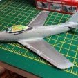
This was a great little kit to build. It fit nicely and was a very fast paced model. I used a matt black undercoat with Vallejo's aluminum color. The pilots are painted with Testor's enamels. The one problem I had with this model is that the some of the decals shredded. They were out of the package but I kept them out of the way and covered so I'm unsure of what could've happened. If you've experienced this and know what might of happened, please comment! Enjoy the photos! -Joanna
-
Hello everyone. Here's my most recent completion - a Vickers medium tank in 1/35 from Hobbyboss. A nice kit, but not without a few issues. The tracks, although separate links, were horrible due to rather nasty plastic, and this necessitated them being installed before painting. I'd normally fit them after the main paintjob, but to be honest, painting them in-situ was fine after all. There were a few errors and omissions in the instructions, but fairly easy to spot and overcome. Detail is pretty good for the rest of the vehicle, and the plastic is nice and hard, but I'm sure there could have been better ways to engineer the kit. It came with no interior, but being a simple open box, scratchbuilding one was pretty straightforward. It was painted with Tamiya acylics (custom colour mix) and weathered with oils and pastels. WIP is here..... 1/35 Vickers MkII - Work in Progress - Armour - Britmodeller.com
-
SPAD 510 7eme Escadre & At War (FR0049 & FR0050) 1:72 Azur Frrom The SPAD 510 was an interwar biplane fighter that was half-way between the stringbags of old, and the modern monoplane fighters, insofar as it was primarily constructed from metal alloys, with only the wing and flying surfaces covered by fabric. It was a development from an earlier SPAD design that was made in response to a requirement from the French Air Force in 1930, and was the only biplane offering due to the encroachment of the monoplane into fighter design. It had an unusually long gestation for the period, entering service six years after the initial design, with many of its earlier problems resolved, and powered by a Hispano-Suiza 12Xbrs V12 engine that drove a two bladed prop and propelled the fighter to a maximum speed of 230mph, which was respectable at the time, and met with Armée de l'Air requirements. It was intended to fly with either two cannons or four machine guns, or a combination of the two, but practically only four machine guns were fitted, while the last two off the production line were equipped with a single 20mm cannon between the cylinder banks to fire in a synchronised manner through the prop. Fewer than 70 were made, and by the time WWII was on the horizon they were already being phased out in favour of more advanced monoplanes, often the capable Morane Saulnier MS.406, although other types were used. With a comparable performance envelope to the British Gladiator, it was clearly outclassed by the enemy Bf.109Es that it would encounter early in the war, although a skilled pilot could possibly achieve a kill despite the disparity. Although many were withdrawn from the frontline to training units, some were initially lined up against the Axis forces as coastal defence before they were ousted and had to move to another more suitable locations. A few were taken on charge by the Germans after the armistice, although they were of little practical use as a fighter. The Kit This is a brand-new tooling from Azur Frrom, with two boxings released initially, one depicting the first squadron to take the 510 on, 7éme Escadre who also provided the pilots for the Weiser Circus aerobatic team, which was named after their squadron leader. The other boxing is an ‘At War’ issue that includes the aircraft that were charged with protecting the coastal areas at the beginning of WWII. The kits arrive in identical-sized end-opening boxes in their usual blue theme, but with different box art on the front and the decal options on the rear. Inside the boxes are two identical sprues of grey styrene, a small clear sprue, the same multi-purpose decal sheet, and an instruction booklet that looks very similar, but is in fact different depending on which boxing you are looking at. This is what I sometimes refer to as “medium run”, as although it does have some aspects of a short-run kit, it is quite accomplished, but not quite up to mainstream in terms of finish to the sprues etc. Don’t be put off one iota by that fact though, as it’s a nice kit and has some good detail moulded-in. Construction begins identically, and doesn’t diverge until right at the end when differences in the exhausts are pointed out in a scrap diagram in the At War boxing, which the modeller would have to scratch build. The cockpit is a flat floor with some details moulded-in, which is added to by fixing a control stick, seat, rear bulkhead, front bulkhead and the instrument panel frame with foot well added, the latter also receiving a decal to depict the instruments. The fuselage halves are closed up around the cockpit once painting is completed, and here you will notice that the halves have engraved panel lines throughout. The lower wings and elevators are all single parts, as is the engine cowling, which has some nice perforated grille detail moulded into it. A scrap diagram shows that the wings and elevators are all intended to be fitted as 90° to the rudder, so get your EBMA wing jig out if you can’t trust yourself to get everything aligned correctly. The small wrap-around windscreen and clear gunsight are added on pegs to the forward section of the cockpit, then it’s time to double the number of wings. The interplane struts are substantial and low in number, resembling an italic capital I, with N-shaped cabane struts mounted on the top cowling in front of the cockpit. These are best aligned with the upper wings during setting of the glue in order to avoid fit issues, and although the rigging is ignored for now, there are full rigging diagrams toward the rear of the instructions to help you make a more accurate model. Everyone has their own technique, so we’ll leave that up to the individual and move on. The main wheels are moulded into their spats and are fitted on long tapering struts, fixing on pegs to the underside of the fuselage, then braced by a pair of wires that attach to the lower section of the legs and a raised area of the underside. The lower wings have blisters on the top surface that have hollows on the underside, which are filled by the gondolas that have the guns moulded into the front, the barrels of which you can drill out for a bit more realism if you wish. At the tail is a skid, and further forward is a stirrup for the pilot’s access, a pair of shackles for stores under the centreline, with a rectangular radiator fairing just beneath the pilot’s feet. After a page and a half of rigging diagrams, the two-bladed prop and a pair of aerial masts are the last parts to be glued in place. As previously noted, the At War boxing has a different exhaust layout depending on which decal option you choose, so be prepared to undertake some DIY to achieve the proposed layout. Markings Each boxing has three decal options printed in colour at the rear of the booklet, all with the same basic scheme that has green upper surfaces with a high demarcation on the fuselage, over a silver underside. The option with the red rudder fin will need to be painted to accept the white 1 in a circle, which is the only variation in painting that I could see. From each box you can build one of the following: 7éme Escadre (FR0049) Nr.26, Red 1, 1ére Escadrille GCI/7 (Spa 15 Bayard’s Helmet), Lt Ozanne, esc. Leader, June 1938 Nr.14, White 5, 3éme Escadrille GC II/7 (Spa 73 Japanese Stork), Dijon, Spring 1939 Nr.25, 4éme Escadrille GC II/& (Spa 78 Black Panther) Dunkirk show, 1937 At War (FR0050) Nr.9, White 8, DIAP (Dépot d’Instruction de L’Aviation Polonaise), Lyon-Corbas, May 1940 Nr.44, White 14, 3éme Escadrille GARC II/561, Le Havre-Octeville, November 1939 Nr.56, Red 6, CIC Montpellier (Fighter Training Centre), June 1940 The decals are identical for the two boxings, so if you change your mind and can find the schemes, you can build any of the above options. You’ll need two boxes if you want to build one from each boxing though. The decals are well-printed, in good register with dense colour and sharpness, including a number of stencils and the instrument panel decal, which is printed in white and hides particularly well in the middle of the sheet. Conclusion It’s a charming little aircraft from the Blériot-Spad stable that was caught between the transition from biplane to metal monoplanes. It’s an unusual aircraft that we don’t get to hear of often, but it is an appealing kit. Highly recommended. Both kits are available from Special Hobby’s webshop, and it’s Special Hobby that moulded the kits in conjunction with Azur Frrom. 7éme Escadre (FR0049) At War (FR0050) Review sample courtesy of
-
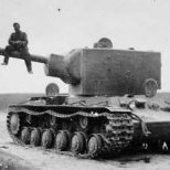
The kit is WNW. Scale 1/32. As usual a good kit, an instruction with some weird instruction steps. So I had to memorize it and built it straight way. The rigging was no problem at all, since we developed a good technique already. You can find all in the forum anyway. The painting is from the Russian Civil War. In summery it took me 2 months beside my job. Happy modelling
- 13 replies
-
- 52
-

-
The kit is WNW. Scale 1/32. As usual a good kit, an instruction with some weird instruction steps. So I had to memorize it and built it straight way. The rigging was no problem at all, since we developed a good technique already. You can find all in the forum anyway. The painting is from the Russian Civil War. In summery it took me 2 months beside my job. Happy modelling
- 10 replies
-
- 37
-
-

-
Bugatti 100 Air Racer (SH72457) 1:72 Special Hobby Bugatti’s streamlined air racer was custom designed for flying the circuits in 1939, using twin engines behind the pilot that ran a pair of contra-rotating props in the nose, which gave it a sleek aerodynamic profile and a compact size. It was also inventive in terms of the tail, which was a V-shape and had a gearbox to split the pilot inputs accordingly between the fins. Before it could be tested and put into the air however, the German invasion began, which forced the engineers to dismantle the aircraft and hide it on Mr Bugatti’s estate until after the war, although he died in 1947 so development stopped there. Over time, the engines were raided for car projects and the airframe fell into disrepair until the 70s when a restoration project began, after which it was placed in a museum. A replica was made using more modern technologies where sensible, and this flew briefly using a pair of more readily available Suzuki engines. After a prop strike during landing, where the aircraft veered off the runway following a brake failure, its third test flight ended in disaster when the aircraft went out of control, killing the pilot who had played a major part in its production, and completely destroying the replica. It had been promised to a museum in England after this flight, which clearly couldn’t now happen. Quite a sad tale overall. The Kit This is a brand-new tooling from Special Hobby, and I really wish it was in my preferred scale, as it’s a rather cool-looking aircraft. Please Sir, can I have one in 1:48? It arrives in a short figure-sized end-opening box, and inside are two sprues in grey styrene, a clear sprue, a bag of resin parts and gasp! No decals. It’s a wee little thing, and that much is brought home when you see the fuselage, which is under 10cm long on the sprues. Construction begins with the transmission at the front of the cockpit, which takes the power from the two engines and adapts them to the contra-rotating prop machinery. The instrument panel is attached behind to the back of a short coaming, which must have made for quite a noisy cockpit. The fuselage halves have sidewall detail moulded-in, and this is painted up before the panel is inserted with a drive-shaft in the front, then backed up with the cockpit floor, seat back and rear bulkhead, with representation of the rudder pedals inserted under the panel next to two tubular drive-shaft covers running forward along the sides of the cockpit. The fuselage is closed up with a fluted insert added in a hole in the spine, and the V-shaped tails with more inserts to replicate the intake louvres on the leading edge, which is fitted later after the wings are completed. Like a lot of air racers, the 100 has a short span, but at the root the chord is wide with a large root fairing, the chord tapering rapidly to the tip. The lower half is a single piece, which has a pair of resin bay wall inserts fitted into the marked recesses, then closed up with the upper wings after a lick of paint. The fuselage is dropped into the space in between the wings, and a pair of small cylindrical pots are inserted into the very front of the fuselage. Underneath, the rudder/tail wheel has an insert with more louvres glued in, with the moulded-in tail wheel painted later. At the rear a pair of bulged resin exhaust outlets are fixed to the fuselage in recesses in the aft section of the wing root fairing, then the landing gear is installed after flipping it over onto its back. The gear legs are a single piece with the wheels clipping into the yoke, and a pair of captive gear bay doors affixed to the outer side, after which the model can stand on its own three wheels. The contra-prop has four sections to its spinner, two trapping each of the two-bladed props in between. The pointy one goes in the front, of course! This is glued to the prop-shaft, and the clear canopy is fitted to the aperture as a single part, with no option for leaving it open. Markings There are two markings options given on the instructions, which are replicated on the rear of the box, one of which is the actual blue scheme it wore, the other a what-if scheme that has red and white fan-shaped stripes on the wings and tail, which looks quite patriotic. From the box you can paint whatever you fancy, but these two are suggested: There aren’t any decals, so they’re perfect for the job. Very light weight and impossible to lose. Conclusion I’m smitten with this little aircraft, and Special Hobby have done a great job with the moulding, using resin where sensible, and giving us plenty of detail in a tiny kit. Now. About my 1:48 one? Very highly recommended. Review sample courtesy of
-
Hello everyone … Seeing as my Cessna build is now in a holding pattern (decals). I thought I would throw my next two high wing builds into the mix. If you’ve listened to me chat over the four years I have talked about a Polish Air Force collection. Not quite the oldest planes in my collection that honor goes to a Nieuport and Albatros D.V In 1920’s Polish A.F. markings. For the P.7a I will be using the Arma kit. And the P.11c is the Azur kit. Please feel free to ask questions, post comments or add thoughts. Dennis
- 10 replies
-
- 10
-
-
- Polish Air Force
- PZL 7/11
- (and 1 more)
-
It's been a while since I posted any progress on modelling work, due mostly to six weeks contract work away from home in London, followed by just over three weeks vacation in Japan. On my return I contracted a chest infection and just felt yuk for a while!. I'm well on the mend now and although I have a handful of projects on the go, I decided I needed a small new project to get my mojo going again. Some constant nagging gentle encouragement from the member for Bury St Edmunds, aka @Courageous, also had a part to play .................. and you will be pleased to know Stuart, I have also done more work on the Vosper, but you'll have to wait a bit to see that! Some of you will have seen some questions I posted in the Interwar section a while back to obtain some information on the Gamecock. Responses were very helpful and encouraged me to start this one which had been sitting in the back of a cupboard for many years. The customary box top artwork, which when I dusted off the box, was in itself enough to get me cutting plastic! A start has now been made....... The cockpit consists of white metal floor and seat, to which I added some wire rudder pedals, which when closed up can't really be seen, but I know they are there......... All closed up with seat inside And the white metal I/P is in there painted up for effect: Lower wing will be next up, together with some work to clean up the white metal front and engine. More to come Terry
- 68 replies
-
- 12
-
-
The second resin kit I'd thought I'd do for the group build. Another parasol monoplane, but a rare one for Yugoslavia as they only had one D.Ibis for a short time for trials before sending back to the factory. They did however buy a load of the CI versions. Anyway, the kit has a prototype sent to Japan with decals only for that aircraft, so I'll have to hit the spares and some freehand painting for the Yugoslav one. A simple kit (oh yeah he says... we will see) with few very well done crisp resin parts. It forms part of a collection of interwar 1930 ~ 1941 Royal Yugoslav Air Force I've been pulling into the stash over the past year. It's one of those themes that unfortunately involves lots of short run and dubious resin models.
- 12 replies
-
- 10
-
-
- interwar
- Yugoslav Royal Air Force
- (and 1 more)
-
Oh boy a chance to actually start building those resin kits I knew I was going to start in this lifetime. So I decided on two, this here is an old long out of production L&M 1/72 scale resin kit bought off eBay recently as I'm in a Yugoslav mood this year and that, unfortunately means having to build short run kits to cover the major types. Few parts, fairly good castings so what the hell could go wrong? I have on order some etched WWI wheel spokes from Eduard which are probably going to be completely useless here as the smallest diameter is 7.2mm while the kits are ??mm since I didn't measure them. A good start.
-
 Hi all... At the urging of the friend @Moa, I decided to rescue a scratch that I had archived for four years and get down to work again with him, and publish it here on Britmodeller. I hope it is in the interest of the community. A brief history. The former Stag Lane aerodrome, if we are located throughout the '20s, was undoubtedly synonymous with De Havilland. But in the previous decade another story ran in those grounds. In the context of the first months of the WWI, the confirmation of the aeroplane as a new military "tool", and the growing need for pilots to "wield" it, is that some contracts are obtained for the opening of aerodrome and establishments for that purpose. In September 1914 Messrs. Geoffrey Smiles and W.T. Warren founded the "London & Provincial Co." pilot school on the ground they bought to the north, in Egdware, where they will install the school and the Stag Lane airfield. The first batch of instruction aircraft were the English-made Caudron G.III with Anzani engines. In 1915 it was added an L&P "Brevet biplane" of own manufacture, similar to the Caudron but somewhat smaller. Success accompanies them, and with the intention of modernizing the aeronautical material they hire designer Anthony Fletcher, recently move away from Martinsyde, to manufacture their own training aircraft. In 1916 London & Provincial Co. introduced the "type.IV" or "School Biplane", with 50hp. Gnome 'Omega' rotary engines, and the undoubted imprint of the works of "Tony" Fletcher. In this case, emphasizing the instruction role, the cokpit is totally open, in tandem, but the student and instructor occupy the same open space. In July of that same year, Flight magazine presented L&P type.IV "Fuselage Biplane", modified for aerobatic flight. The fuselage is narrower, the cockpits are closed and differentiated, the wing and the tail is larger. The engine is an 80hp Anzani. In October this aircraft will obtain the record of loopings in a demonstration on the Hendon aerodrome. In the remainder of the War the London & Provincial Co. will be assigned as part of the RAF "18th wing school of instruction". I couldn't find the precise information on how many "School Biplane" and "Fuselage Biplane" planes were manufactured by the London & Provincial Co. on Stag Lane, but it can be said that four type.IV "School Biplane" planes reached until 1919 ( K-117 / G-EABQ; K-118 / G-EABR; K-119 / G-EABS; K-138 / G-EADT), and the looper type.IV "Fuselage Biplane" G-EAQW until 1920. After World War I, all contracts and subsidys related to the conflict are cancelled immediately. The aviation industry will undoubtedly be the most affected area. We already know the becoming of many manufacturers, designers, and the urgency of civil and commercial aviation. The London & Provincial Co. will also be found in this situation. In January 1919, 40 vacancies were announced for pilot courses and the arrangement of Stag Lane airfield and its aircraft for air events and some commercial flights. The company was in a reorganization process at the same time that a dispute began with the Department of Civil Aviation. Finally the license is not renewed and in July of that year the "London & Provincial Co." closes its doors. With the closure of "L&P" the four L&P type.IV with a 50hp Gnome engine are also lost trace. The facilities will survive and part of them will shelter the brand new company that Geoffrey De Havilland was creating, which will be formally established on September 26, 1920. As for the looper L&P type.IV "Fuselage Biplane", sometime in 1917 it was acquired by the Richmond company "Whitehead Aircraft Company", another contractor of elements and aircraft for the War Office, to be part of the group of aircraft from your flight school. The first jump tests will be done on this machine with the Calthrop parachutes, enlarging the front cockpit to facilitate the departure of the passenger. According to the images it can also be seen that there was a redesign of the landing gear by one of the "anti-overturn" type, and of the nose of the fuselage behind the 80hp Anzani, which still maintained it. https://youtu.be/tttHD9s0jrI Within the same process of company reorganization after the end of the War, the "Whitehead Aircraft Company", which also carried debt and capitalization problems, finally entered bankruptcy in 1920, with the auction and liquidation of its assets. The L&P type.IV "Fuselage Biplane" registered by Rodney A. Whitehead as G-EAQW in February 1920 will be part of these asset sales. In an article published in Flight magazine on May 20, in addition to reviewing his history, he can be seen in a image with a shiny new look and in good flight conditions. The landing gear returned to its original configuration, a new livery with well-placed regulatory registration, and a new 100hp Anzani engine more powerful. If the plane had a buyer or not, it will disappear from the registrations that same year. The planes I decided to represent are the London & Provincial type.IV "School Biplane" (no painted registration) from 1919, and the London & Provincial type.IV "Fuselage Biplane" G-EAQW from 1920. It is a work that I am resuming after four years of suspending it. My scratch speed is not the same as my friend @Moa's, but slowly I will show some progress. Now I definitely want to finish it. Here are some images of the model construction process. They are all from 2016. For now they are like this... Cutting the first plastics... Control sticks... The first parts glued. Although there is some information about the interiors, basically almost everything is improvisation, taking as inspiration the most documented planes of the time and similar to these models. The RAF BE.2 was a good reference. In this link an original drawing of the instrument board of the L&P "Fuselage Biplane"... The materials used for construction are varied: there are wires of different thicknesses, stretched plastic, plastic sheets, cyano-impregnated paper, paper tape to make the seat belts. The model begins to take shape... The first steps to develop the cylinders of the Gnome and the Anzani. Mold making for the "proto-cylinders". The complete fuselages have been covered. The Anzani and the Gnome block's with the sites marked for the location of the future cylinders. Proto-cylinders to start working on the details. The Anzani's master cylinder is finished. Cylinder cloning is ready. At this stage a problem arose. This was when I discovered that the 1920 L&P G-EAQW had some details different from the 1916 original. I found its history with the Whitehead Aircraft..., and the doubts with the livery of this aircraft. A new drawing... ...and the corrections began with major surgery. The simplified instrument board of the front cockpit was replaced by a simulation of the fuel tank. That site would be used for test jumps with the Calthrop parachutes. No one saw anything... ^ ^ We start with the wings. Stretched plastic to simulate the fabric. First step. We continue with the engines. It is time to put the cloned cylinders in their places... We start with the most complex Anzani and its ten intercalated and slightly desradiated cylinders. Everything stayed in its place. This is the current moment of the L&P scratch. I am not very satisfied with the Gnome Omega because it was slightly out of the correct diameter. Maybe I'll correct it... I hope I didn't bore you. I will be showing the progress. Matías
- 39 replies
-
- 27
-
-
-
- Stag Lane
- Anthony Fletcher
- (and 1 more)
-
Hello... I greet the community from Argentina. I see that I joined Britmodeller in 2015, but I never wrote anything... I can assure you that I'm not a ghost! ^ ^ I am a lover of everything that has wings produced between 1919 and 1939... I am also very tempted by the WWI planes, and the beautiful curves of any time (of some planes too). Although the interwar world is usually silvery with some well-documented colors, being a ghost can sometimes be very convenient at the moment of interpreting lost livery in b/w. I embrace this hobby from the scratch, drawings, and some projects that revolve around them. My English is very bad, so I apologize in advance. If the subject be up to my knowledge, and I have time, it will be a pleasure to participate in Britmodeller. Saludos Matías
-
Hi all, Here is my latest build, the 1/48 Bristol Bulldog kit from Lindberg. This kit traces its lineage right back to 1968, which makes the moulds 52 years old…! Extensive modifications were made to the kit, including reworking all of the external surfaces (the kit comes with horrible textured fabric surfaces all over and raised panel lines), scratchbuilding the cockpit (the kit cockpit is non-existent), correcting the underside of the nose, correcting all of the nose panels, adding the chin radiator, adding the under-belly panel and circular under-fuselage fairing, replacing and detailing the engine cylinders, pushrods, sparkplugs and other details, scratchbuilding the windscreen, adding gun sights, bomb racks, navigation lights, and a whole bunch of other changes too numerous to list here. I painted the machine in the (rather boring) markings of a Royal Australian Air Force (RAAF) machine, using Red Roo decals for serial numbers. The national markings were spray painted. RAAF machines did not appear to be fitted with radio equipment. No photographic evidence found to show that RAAF Bulldogs sported antenna wires, nor do any photos show that RAAF machines sport lower starboard wing mounted air-driven generators (though the fittings for said generators remained). RAAF machines could be seen with various combinations of bomb racks, upper wing navigation lights and lower wing flare racks. Any combination can be seen. The combination I chose was bomb racks and upper wing navigation lights. The build took me just under four months all up. It was a fun build, but it fought me most of the way. It’s good to finally have something off the bench for the year… Anyway, here are some pics: Build progress and more detail shots are here - All comments, criticism and feedback welcomed. Cheers, BC
- 63 replies
-
- 80
-
-
-
Hello everyone. I'm still new here..., so here I'm trying my second message. These are my works in progress. For now, all suspended in different stages of construction, for some error that requires a major correction, for boredom, or because the stage that begins requires special attention, especially the development of engines... Anyway, now I am dedicated to some works that occupy me all the time, so necessarily there they will be waiting for the best moment to be finished. Artigau 'Coronel Pringles' ... it was an airplane of Argentine manufacture that flew between 1917 and 1920. It is the work that is first in the waiting list. I have to make the Gnome Omega 50hp, make the simil fabric of the wings and fuselage, and everything else. London & Provincial ... they are the models 'Brevet biplane' (Gnome Omega 50hp), and 'Fuselage biplane' (Anzani 100hp.). It is necessary to refine the details of the fabric of the fuselage and the wings, besides carving the corresponding ailerons. The cylinders of the engines are already made, only the blocks are missing, and everything else... LFG V.130 Strela ... the huge wings of this plane are stored in another box. The Benz Bz-IV engine and all its parts are already made, I just have to assemble it. Work details on the fuselage. Assemble the wings and tail, and continue with the construction of the rest of the parts... FEIRO Daru ... an interesting Hungarian passenger plane from the early 20s. This project I suspended almost at the beginning, since the development of the nose for the Hispano-Suiza was wrong. It will require a lot of attention and better interpretation of the images.
-
So as the two current builds reach the painting and waiting phase, I've moved on to the next attempt in stash reduction. Now, biplanes have always presented me with a bit of a problem, I've always struggled to get that top wing balancing properly and sturdily enough. So what better way to face this fear than to attempt building one a few most of those present in my stash. Since four are matchbox, I know from my previous fury build that someone's actually thought construction through and the central struts will be well placed and held be other parts. Since the others are Airfix and Frogspawn, I may have more trouble later... So what kits are making an appearance? The first is part of the reason for the build, pulled down of the dread SoD after taking flight and various delicate parts snapping, one Hawker Demon. Next, the Frogspawn. A Blackburn Shark Mk.II Then the second Airfix kit and first Matchbox. A Bristol Bulldog and Armstrong Whitworth Siskin. One Matchbox Gloster Gladiator with a bit of AM.... And finally, Matchbox's Supermarine Walrus. There's also a Matchbox Stranraer in the wings, but she will appear later in the thread.
-
 Hello fellow modellers, I hope you are having a pleasant weekend. I am building a 1/72nd scale Amodel Polikarpov I-16 Type 5. Unfortunately something strange happened to the canopy. It is no longer clear, it has gone a milky white and is now opaque. I live in Queensland Australia and had stored it in a little parts tin. I feel maybe humidity or some other factor related to heat caused this change, as it hasn't happened to canopies stored in normal kit boxes or zip-lock bags. It has probably been cooked! I have tried emailing Amodel and they cannot provide a canopy, only complete kits. I then found out that Falcon list an I-16 canopy in their Russian canopy 1/72 set. Unfortunately it isn't listed as an individual item in the Squadron range, so I would have to buy the complete Falcon set. It would be better value for money to buy this set than another I-16 kit, but I can't find any pictures of the Falcon set and wondered if the canopy included is the correct early type I need? It needs to be quite 'tent' shaped and fully enclosed. Does anyone know what type is in the set? Finally, I am hoping to model a Spanish Civil War Example (I know the kit has probably the wrong type of wings. I can live with this - this time ). I did wonder if anyone knows of a picture showing a SCW Polikarpov Type 5 (6?) with the later, open, round windshield rather than canopy? So far I have only seen this on type 10's, but if any type 5's like this existed my problem is solved. I have a good non-fogged one as I left it in the kit box rather than in the 'cooking' tin! I wonder why it became so fogged in that little tin, was it really that warm in there? Thank you for reading All best regards Tony
 -
Has anyone built the Contrail kits such as the Hinadi,Hyderabad,Virginia, etc. Anything i should look out for ? john
-
Hi, have been slowly working on the CMR 1/72 scale DH 9A, and I’m finally getting close to decaling. The plane I’m going to model is the E-828 “A” of the 27 Squadron in India in 1927, and I’m wondering if the 27 Squadron has been known to use any underwing serials or letters during this period? Have looked through the Datafiles, the Profile on DH9A, and some other sources, but can’t find any clear pictures showing them. In some pics I could faintly imagine seeing the individual plane letter, but really hard to tell for sure. I’d be really grateful for any info on this before committing myself one way or the other. Below the current status on the model Petri
-
Yesterday I was possessed from the insane idea to explore the vacum formed stash and I found an old 1/72 scale Contrail Supermarine Scapa. Many years have passed since I assembled my last one but this kind of kit remain still my first love. I cannot face the resin kit without inconvenience while the vacs still give me strong emotions. Unfortunately the vacs companies on the market are now very few, But coming back to the kit I made the first little boring step, preparing the pieces. Now I have to plan the "interior design" and this is the real endeavour because What I was able to fid in the web are these little images. If someone could help me with some details it would be very appreciated. Anyway It's not really a problem because the crew emplacements are not really visible so the main target is to assemble a credible cockpit Happy modelling to you Ezio and now the little I found on the interior
-
Hobby Boss's new catalogue shows lots of lovely interwar tanks. http://scalemodels.ru/news/9588-katalog-HobbyBoss-2016-2017.html I need to stock up on more pipes, iron and brass paint, and gears; so many to convert to steam tanks!
-
 Hello! Here is my finished SM.79 Sparviero. The construction took half a year, actually I was tired at the end. As usual the Italeri's painting guide was false, and the camo. does not match on the two only shots what I've found about the 28-11, however are taken from the same side. So my camo are 'something like that'. I had the chanse to paint it to the 2 tona camo, but I didnt liked it. The flash light may show the colors lighter than these actually are. And here it is: And finaly, You can read the project in this topic. In some words, I can say, this is a good kit, and gives a satisfiing result OOB too, but be careful with the aerials wich beeings are depending on series, and with the painting.
- 19 replies
-
- 35
-
-
Hello, I've been bitten by the bomber bug and wonder what kits are available in injected plastic and in 1-72. These are the types that I know about, can you add more? Martin MB-2 Martin B-10 Douglas B-18 H.P. Hampden A.W. Whitley Hawker Hart Vickers Vimy Bristol Blenheim I Fiat Cicogna S.M.79 and 81 CANT Z.1007 Tupolev SB Tupolev TB-3 Amiot 143 Potez 540 Bloch 200 and 210 Heinkel He.51 Junkers Ju.86 Junkers Ju.87A Heinkel He.111B, ecc. Dornier Do.17 Kawasaki Ki.48 Mitsubishi G3M Aero A-100 Admittedly I know very little about the single engine types.
-
Avia BH-22 Czechoslovak Training Aircraft 1:72 Fly The BH-21 was a single-seat fighter aircraft designed by Pavel Beneš and Miroslav Hajn of Czech aircraft manufacturer Avia. Entering service in 1925, the aircraft became the mainstay of the Czech Air Force in the interwar years. A number of examples were license built in Belgium and used by the Belgian Air Force as well. Powered by a 304 HP V8 engine developed by Hispano Suiza, the BH-21 was capable of 152 mph and could achieve a service ceiling of over 18,000ft. Armament was comprised of a pair of .303 inch Vickers machine guns mounted in the front fuselage above the engine. The Avia BH-22 was a trainer aircraft developed from the BH-21 fighter. The armament was deleted and replaced with a camera gun, whilst the airframe itself was strengthened to allow the aircraft to cope better with aerobatics. Thirty were produced, with a number of examples finding their way into private ownership. Although a relatively new name on the scene, Fly have already produced some interesting and much sought-after types, including a 1:72 Armstrong Whitworth Whitley and a 1:48 BAC Jet Provost/Strikemaster. The Avia BH-22 will probably be less familiar to you, but it is nonetheless good to see Fly continue their tradition of tackling some of the less obvious subject out there. Inside the sturdy, end-opening box are two sprues moulded in beige plastic, a small bag of resin parts, an injection moulded windscreen, a vac formed windscreen and a sheet of decals. The quality of the injection moulded parts looks very good. There is little or no flash and fine details and features such as the fabric wings have been captured very well. The cockpit is comprised of seven parts, including a floor, seat, control column, instrument panel, rudder pedals and rear bulkhead. The level of moulded detail is pretty good. Some basic structural details are moulded in place on the inside of the fuselage halves, and there is some basic raised detail on the instrument panel. The seat is cast in cream coloured resin with harnesses sculpted in place. It looks an excellent piece of work by Fly and should show the cockpit off the best effect. The radiator, mounted under the centre of the fuselage, is cast in resin too. Once the cockpit is finished, you have both a vac formed and injection moulded canopy to choose from. I like this approach as it encourages the builder to try the vac formed version, with the knowledge that should it go wrong, there is an injection moulded version to fall back on. The rudder is provided as a separate part, which means it can be finished in the deflected position if desired. The horizontal stabilisers are moulded as solid parts, as are the wings. The fabric effect is quite nicely rendered. The upper wing has locating points for the struts, but the lower wing just has raised bumps which will have to be drilled out in order to fit the struts in place. Diagrams are provided to help the builder line everything up properly. A choice of exhaust systems is included. One is a full length version which runs down the side of the fuselage, the other is a shorter version which is cast in resin. The undercarriage is pretty nice, and a choice of two different wheels is provided. From the look of the sprues a pair of skis is provided too, but these are not used for any of the aircraft depicted on the decal sheet. The decals themselves look pretty good, although there were a couple of very slight smudges on the sheet provided in my kit. Four options are provided: Avia BH-22, Prague-Kbely, finished in a green/brown/sand camouflage pattern; Avia BH-22, VLU Military Air Training Establishment, Prostejov, Early 1930s, finished in clear doped fabric; Avia BH-22, Cheb, 1933, finished in olive green; and Avia BH-22, Prague-Kbely, finished in olive green. Conclusion This is an interesting kit of an attractive interwar biplane which will bring something a little different to your display cabinet. If you’ve got a couple of similar kits under your belt and are prepared to take your time, this looks as though it should be a rewarding and enjoyable kit to build. Recommended. http://www.hannants.co.uk/product/YLF72016'> Review sample courtesy of