Search the Community
Showing results for tags 'ICM'.
-
Hello everyone I'll be using the Revell rebox of the ICM tooling. Converting the A4 to the C6. It would be easier to have there own boxing of the C6 but I had this in the stash so waste not want not. So there will be some scratch building to do. I also have the aims radar and nose cone to use.
-
 WWII German Mortar s.Gr.W34 with or without crew (35715 & 35716) 1:35 ICM via H G Hannants Ltd The Granatwerfer 34 was an 8cm mortar in service with the German armed forces during WWII, continuing through the entire conflict thanks in part to its accuracy and rate of fire, plus the ability to add additional powder charges to the munitions to increase the range over standard. Over 70,000 units were made, and over 70m rounds were manufactured in either blast, fragmentation or smoke variety, with some training rounds for practicality. They were typically crewed by three to four soldiers, although fewer men could operate it if there were sufficient rounds already nearby and the need arose. The Kit This new kit from ICM has been produced in two boxings, one with a crew of four soldiers, the other as a stand-alone item that can be used as diorama fodder or as stowage on a vehicle. Each kit is delivered in an appropriately sized top-opening box with the usual captive flap on the lower tray, and the sprues are enclosed in a resealable clear foil bag, hiding the instruction booklet underneath. German Mortar s.Gr.W34 (35716) Consisting of one sprue and a small instruction booklet, the mortar barrel is assembled from two halves, then has the two-part adjustment mechanism clamped around it from both sides that receives the top of the support frame and another adjustment lever. The bottom end of the barrel is inserted into the base plate, which has the self-entrenching fins moulded into the underside, a nice detail that will need trimming back or removing if you are fixing it to a flat base. There are three ammo boxes included on the sprue that have one end moulded separately, and can either be depicted closed by gluing the lid over them, or with three rounds in place and the lid glued open. The instructions show the rounds painted orange or green, and a quick rummage round Google shows up pictures of both colours, although the paint has darkened over time. German Mortar s.Gr.W34 with crew (35715) The box for this set is slightly larger because it contains three sprues, including the same sprue as the kit above. The largest sprue includes parts for four crew figures, three of whom are kneeling in various poses, the other is running with an ammo box under each arm. Each member of the crew is dressed in standard Wehrmacht uniform for the period with stahlhelm and either a Kar98 rifle or MP40 machine pistol slung over their shoulders. The third sprue contains a variety of accessories that are appropriate for WWII German troops, including helmets, pouches, holsters, binoculars, mess kits, water bottles, gas mask canisters, and even a spare MG34 with ammo cans if you should need it. The figures are well-sculpted and moulded with separate torsos, heads with flat tops, arms and legs, with some of the hands separated for detail’s sake. One figure also has one of his coat tails separate, and each figure has their own over-shoulder bag that has matching straps moulded into the torso of the figure. The ammo boxes and rounds for the mortar are included on the mortar sprue, and the one not under being carried can be assembled opened or closed as described above. Conclusion Get whichever set you prefer and enjoy the detail. Excellent sculpting on the figures, and fine detail on the mortar with sufficient accessories to satisfy most needs. Highly recommended. Available in the UK from importers H G Hannants Ltd. Review sample courtesy of
 -
Unimog S404 ‘Koffer’ (35136) 1:35 ICM via H G Hannants Ltd Unimog was the brand-name used by Mercedes for their truck, tractor and commercial vehicle range that began post WWII as an agricultural brand, initially built by another company for them whilst using their engines. The range broadened in the late 40s and early 50s to include trucks, of which the 404 series was one, entering production in 1955. It is a small (1.5 tonne) 4x4 truck that was driven by a 2.2 litre M180 straight-6 Mercedes engine and has impressive off-road performance due to a change that had been required by a customer, the French Army, who wanted the spare tyre to be stored clear of the load compartment. The designers altered the shape of the rear chassis rails to allow the wheel to sit under the floor, the downward sweep giving the chassis extra flexibility that smoothed the ride on rough surfaces, assisted by coil springs, rather than traditional leaf springs. The four-wheel drive system could be disengaged on smoother ground, leaving just the rear wheels engaged, thereby saving fuel and wear on the front drive-shafts, and generally improving performance all round. The 404 series was the most numerous of the Unimog line, and was available as a short or long-wheelbase chassis, with the shorter option phased out at the beginning of the 70s, while the longer wheelbase continued on for another decade before it too was retired. The nascent West German Bundeswehr were a major customer, buying substantial quantities of the 404S as a workhorse for their forces, taking on many roles in their service. A total of over 62,000 of the 404S were made over its lengthy production run, with many of them still on and off the roads to this day due to their rugged engineering. The name Koffer was short for Kofferaufbau, which roughly translated via Google stands for case body, which often had a turbo-heater fixed to it as well as a variety of windows and ventilation outlets that varied with time and use. The Kit This is a rebox with additional sprues of a new tooling from Ukrainian company ICM of this Bundeswehr pillar of their transport arm. It arrives in a top-opening box with a captive lid on the lower tray, and inside are seven sprues of grey styrene, two clear sprues, five flexible black tyres, a decal sheet and a glossy printed instruction booklet with colour profiles on the rear pages. Detail is excellent throughout, and includes a full chassis and engine, plus the bodywork and new load area, all crisply moulded as we’ve come to expect from ICM. The grille of the vehicle is especially well-done, as are the coil springs on each corner, and the wheels are very neat with multi-part hubs. Construction begins with the ladder chassis, which is joined together with a series of cylindrical cross-members, plus front and rear beams, the latter braced by diagonal stiffeners to strengthen the area around the towing eye at the rear. The suspension is next, adding an insert to the opposite side of each spring to avoid sink-marks, but care must be taken to align them neatly to minimise clean-up afterwards. Triangular supports for the fuel tanks are added on each side, then attention turns to the six-cylinder Mercedes motor. Beginning with the two-part cylinder block and gearbox, the basic structure is augmented by ancillaries, fan, pulleys and drive-shaft for the front wheels, after which the engine is mated to the chassis and has the long exhaust system installed, adding a muffler insert around the half-way point, and siting another drive-shaft adjacent. Two stamped fuel tanks are each made from two parts, with the forward one having a filler tube and cap glued to the side, sitting on the out-riggers that were fitted to the chassis earlier. The front axle is made up from five parts to capture the complex shape of the assembly, to be installed between the suspension mounts and mated to the forward drive-shaft, plus the stub axles for the front wheels. A stowage box is made for the opposite side of the chassis from the fuel tanks, then the rear axle is built with similar detail and part count, fitting between the suspension and having larger circular stub-axles that have the drum brakes moulded-in. The front wheels have separate drum brakes, and both front and rear axles are braced with damping struts, while the front axle has a steering arm linking the two wheels together, with more parts connecting that to the steering column. With the chassis inverted, the front bumper and its sump guard are fixed to the front, and a curved plaque on the rear cross-member, plus another pair of diagonal bracing struts for the rear axles. Each wheel is made up from a two-part hub that goes together much like a real steel hub, but without the heat of welding, around the flexible black tyres. The front and rear hubs are of different design, so take care inserting them in the correct location. Lastly, the chassis is completed by adding the radiator and its frame at the front of the vehicle. The cab is the first section of the bodywork to be made, starting with the floor, adding foot pedals, shaped metalwork around the gearbox cut-out, sidewalls and the internal wheel wells below the floor level. Several additional parts are glued beneath the floor for later mounting, then the lower cab is built up on the floor, including the front with recessed headlight reflectors; bonnet surround, dashboard with decal, plus various trim panels. The floor is then lowered onto the chassis with four arrows showing where it should meet with the floor, taking care with the radiator. Once in place, the bonnet and more interior trim is installed along with a bunch of stalks between the seat positions. The seats are made from the basic frame to which the two cushions are fixed, much like the real thing, then they’re mounted inside the cab, followed closely by the two crew doors, which have handles on both sides, and pockets on the interior, and can be posed open or closed. More grab-handles, controls and other small parts are fixed around the dash, and the windscreen with two glazing panels are put in place, with a highly detailed steering wheel that has the individual finger ‘bumps’ on the underside, and for your ease, it’s probably better to put the wheel in before the windscreen is fixed in place. The cab is finished off by adding the cabrio top, which starts with an L-shaped top and rear, to which a small rectangular window and two side sections are added, dropped over the cab when the glue is dry and the seams have been dealt with along with the side windows that consist of the frame with two glazing panels in each one. Later on, the recessed headlight reflectors should be painted with the brightest metallic you can find before they are covered by the clear lenses and their protective cages, joined slightly outboard by combined side-light/indicator lenses, a choice of two styles of door mirrors, and a pair of windscreen wipers to keep the screen clear. The load bed begins with a flat rectangular floor, several supports and two lateral beams that takes the weight of the bed once complete. The sides of the load area are covered with raised and recessed detail, and comprise four parts, one for each side, with windows and optional grilles added from the inside. The roof has two options, one has moulded-in hatches, which are covered by a tubular framework, the other is much simplified. A set of poles are glued to the side in a rack, handles are added to the recessed areas of the doors, with a frame fixed to the front of the load box to carry the turbo-heater that is built next as a clasped case and a tubular assembly. Underneath is a rack for a nicely detailed jerry can, several stowage boxes and optional racks or steps, and the spare wheel on a dropped C-shaped mount, built in the same manner as the road wheels. A choice of two number plate holders is hung under the rear, also holding the rear lights for that side, with another less substantial part on the opposite side. Markings You might guess that most of the decal options are green, but there is one in NATO camouflage that is so typical of how I remember the Unimog in West German service. From the box you can build one of these three: Bundeswehr Artillery Unit, 1970s Bundeswehr Aviation Unit, 1970s Bundeswehr Armoured Unit, 1980s <ul style="list-style-type:upper-alpha"> The decals are printed by ICM’s usual partners, and consist of dials, number plates, stencils and a few other small decals, with good register, sharpness and solid colours. If you don't think you have the correct paint shades in stock for this kit, there is a new Acrylic Paint Set from ICM specifically designed for this model, our review of which you can see here. Conclusion The Unimogs were ubiquitous in Cold War West German army service, so there ought to be a good market for a modern tooling of the type, with many more variants still to come in due course. Highly recommended. Available in the UK from importers H G Hannants Ltd. Review sample courtesy of
-
Bristol Beaufort Mk.IA w/Tropical Filters (48311) 1:48 ICM via H G Hannants Ltd The Beaufort was originally designed as a torpedo bomber by Bristol, using the experience they had gained in developing the then-excellent Blenheim. They were ready in time for the outbreak of WWII, and as well as their prescribed role, they were also used as light bombers, undertaking many ‘Rhubarb’ missions over enemy territory in the so-called ‘phony war’, embarking on daylight missions that saw heavy casualties, although the accidental loss tally outstripped combat losses, surprisingly. Roughly 1,200 were built in the UK, with the total being elevated to almost 2,000 by additional Australian-built airframes that were known as DAP Beauforts. They were rapidly overhauled by the German fighters and were withdrawn from frontline service as early as 1942, by which time they had also been tasked with Aerial mine-laying. From then on, they were assigned to serve away from the front, and saw extensive use as a trainer, which might go at least some of the way to explain the high attrition rate due to accidents. The Mk.IA had an improved turret fitted at the rear of the crew compartment spine, that was notable because it was more square in profile, and torpedo bombers were fitted with early ASV radars , the antennae for which were mounted on the leading edges of the wings. A further development of the Beaufort was the Beaufighter, which used important components of the Beaufort that included the wings and engines, with a new cut-down fuselage that was comparatively low and streamlined, with a powerful cannon armament under the nose that was useful in its assigned duties as long-distance heavy fighter, and later nightfighter, where it excelled. Some obsolete Beauforts were even converted to Beaufighters to make further use of the shared parts, which gave many of the original airframes a more honourable end than they would otherwise have seen. In an attempt to improve on the original Mk.I that took up the majority of production, the designers created additional variants that used other engines, had faired over turrets when they were to be used as trainers, and even a project that saw the fitment of a pair of Merlin XX engine that didn’t achieve the desired effect, so was cancelled, in much the same manner as the Merlin powered Beaufighter that managed to be “underpowered” despite the pedigree of the engines that propelled it. The Kit A lot of modellers that build in 1:48 have been waiting with baited breath for this new tooling from ICM, and now it is with us, despite the horrible circumstances that besets the Ukrainian people at the time of writing. This initial boxing rightly covers the Mk.I torpedo bomber, and there is another boxing on the way with a tropicalised engine fit that should arrive pretty soon. This new issue arrives in a reasonable-sized top-opening box with their usual captive lid on the lower tray. Inside are eight sprues in mid-grey styrene, a large clear sprue, decal sheet and glossy instruction booklet that has colour profiles on the rear pages. Opening the resealable bags reveals the detail that has been lavished on this kit that includes lots of internal ribbing, a set of ribbed flap bays and flaps, a representation of both banks of the Bristol Taurus engines, detailed gear bays and bay doors, and a torpedo to complete the package. Construction begins with a narrow torpedo bay under the fuselage that is glued to a section of the aft floor, then detailed with ribs, flipped over and joined to a bulkhead that has a doorway cut in it, then has a chute made up on one side before it is attached to the rest of the interior floor, which is initially free of detail, apart from underneath, where it has bomb shackles moulded-in, and a semi-cylindrical bay toward the front of the fuselage, which will allow the torpedo to nestle into the fuselage part way. The starboard fuselage half has an insert fitted into the wing-root depression to match the crisp moulded ribbing that is all over the interior as far back as the trailing edge of the wings, and extends into the tail-wheel bay. The side windows are inserted from inside, swapping the rear one out for an opaque cover if appropriate, then the floor is mated on several slots into the fuselage sides ready for the twin spars and a good quantity of detail. The forward spar is detailed with four parts to depict the radio gear with a plotting table below it, and on the other side a section of fairing is fixed, then the assembly is glued into its slot, joining the bottom of the spar with the fuselage blank. The cockpit is a two-tier assembly that is started by joining the two halves of the side console together, adding a raised floor panel, the instrument panel with five dial decals and rudder pedals, a short half-bulkhead and the swivelling front seat. Another simple seat is made up and glued to the rear spar along with another step-like fairing, and it too is slipped into the rear slot in the fuselage and glued in place. The pilot’s seat is made up from two parts and has a bow-tie control column placed in front of it, while to the rear, an Elsan toilet is dropped onto a raised plinth in the rear fuselage floor. The tail wheel bay is made up from ceiling with two small bulkhead ends, and it is glued into the very rear, which already has ribbing moulded into the sides. The tail-wheel and strut is a single part than inserts in the bay ceiling on a peg, so can be left off until after main painting. The port fuselage half is prepared in a similar manner to the starboard, save for the optional rear window, and a 0.9mm hole that is drilled in the ceiling. Just before closing up the fuselage, another detail part is fixed to the bulkhead behind the pilot’s seat, with more glued into the nose, which might be better added before you paint the cockpit. The main canopy is glued over the cockpit aperture, and the nose is glazed by four additional clear parts, and a choice of port-side aft door with a circular porthole or gun port fitted over the hole in the fuselage, which can have a Lewis machine-gun with dinner plate magazine on a spar across the opening. If you are installing the gun, the clamshell door part should be left off. The Beaufort had mid-mounted wings, so each one is separate, and made from two halves. The port wing has a small landing light bay inserted before it is closed, and a small dome is removed from the leading edge, then the clear glazing is inserted once the glue has set up. A clear wingtip is fitted, and a one-piece aileron is added and able to be offset if you feel the urge. You also must make a choice whether to fit the wing surface over the inner flaps with a trio of strakes in a nacelle extension, or a straight section with curved root fairing. The same process is carried out minus the landing light bay on the starboard wing, then both wings are slotted over the two spars that have corresponding guides moulded into the inside of the wings to ensure good location. The elevator fins are each two parts and are mounted in the usual slot/tab method, to be joined by one-piece elevators and rudder, which the latter having a pair of horns near the hinge. Two flap sections are added to each wing’s underside, then the two nacelles are made up from halves along with a bulkhead near the front, and another that is glued into the wing before the nacelles are put in place. The roof of the bay is free of any detail, and is the location that the twin strut gear legs and their actuators are fixed once they are built up. The main wheels are each two halves, and they flex-fit into the lower section of the main leg, which has a curved tubular framework added to the top section, probably to assist with the smooth opening and closing of the door bays. The lower section of the main gear forms a twin triangular framework that is linked by several cross-members before the lower section is glued into the sockets in the upper section, and has another pair of actuators added at the rear to brace the top section. Both assemblies are inserted into the bays on each level of the ceiling, then the twin bay doors with their ribbed inners are added to the sides of the bays on hinge tabs. At the same time, the bomb bay has a small insert attached to the front bulkhead to add detail to the area. Each Taurus radial engine is formed from two well-detailed banks of cylinders with a circular collector ring attached to the centre by three stators, plus a complex system of tubes installed around the circumference in between the cylinders, and another at the rear of the engine that has a square peg at the back for fixing them to the wing through the cooling flaps at the rear of the cowlings. Two holes on the top of the nacelle receive a different two-part intake, then the cowling is wrapped around the engine, comprising two halves and a pair of curved exhausts for each engine. She’s looking very much like a Beaufort now, but needs some defensive armament in addition to the optional Lewis gun in the side. The new mid-upper turret is mounted in the back of the cockpit “hump”, and is built upon a separate section of the fuselage with a circular base that receives the guns’ mount and gunner’s bicycle-style seat below the lip, gluing the majority of the turret into position along with a fairing lip around the end, then deciding whether to mount the clear glazing in the top of the nose, or the alternative that mounts another two Lewis guns in the nose. The bomb/torpedo bay forms a cruciform shape when viewed from below, as it was lengthened to accept the torpedo, and has the mount fitted into the wider centre section, and if not carrying a torpedo, two inserts close off the bomb bay from its two narrower sections. The bay doors are in three sections, the narrower front and rear sections having one door per side, while the wider bomb bay section has two doors each side that fold together, minimising the aerodynamic drag, as well as fitting in the space below the aircraft when on the ground. If you plan on posing all the bay doors closed, there are three additional conjoined parts to ease your path, which is always nice to see. The torpedo has been seen in a separate box before, and its build is covered on the last page of instruction steps, making it up from two halves, adding a three-part H-tail with twin spinners, and another spinner-plus-spacer at the business end. There are also five steps to create a trolley for moving your Torp about and loading it onto the Beaufort on rising scissor-links if you want to add a bit of diorama appeal to your model. The torpedo is mounted with all bay doors open, and glues onto a long curved rectangular frame in the centre of the bomb bay. While the model is inverted, the underslung nose turret can be built from three parts for the gun and two-part dome, or a blanking plate is fitted over the aperture. A pitot is also mounted under the nose, a towel-rail antenna under the fuselage, and three small outlets are mounted on the wings and just behind the bomb bay. Back on its wheels, the cockpit hump is detailed with two more antennae, and another either flush with the roof in a typical D/F loop fairing. The radar antennae are reminiscent of TV aerials, formed from a main antenna with several dipoles perpendicular, one under each wing, mounted on two brackets that fit into holes drilled in the wings earlier, and another offset under the nose on a single post. These are most definitely best left of until the very end so that they survive without damage. Markings ICM have begun to include templates for masking material with each of their new kits, which can be found just in front of the colour profiles for you to place tape over, cut around and apply to your model, thanks to drawings above that indicate what goes where. There are four decal options included on the sheet in a variety of schemes. From the box you can build one of the following: DD959 Q, No.217 Sqn., Malta, 1942 L9965 T, Mediterranean Sea region, 1942 DX157, presumably Indian Ocean region, Spring 1944 EK979, RAF Training Unit, Bilbais, Egypt, 1944 The decals are printed by ICM’s usual partners, and include dials for the instrument panels, with good register, sharpness, and solid colours. As is common now with ICM kits, there is a page of the instruction booklet devoted to the masking of the canopy, using the printed shapes on the bottom of the page and the diagrams above to allow you to create your own masks if you wish. It goes up to 64 thanks to the copious glazing of the Beaufort. Conclusion I was looking forward to the initial release, and I’m wasn’t disappointed, and this rebox with new parts is just as good with another theatre of operation opening up in terms of subjects. It’s another Beaufort in my preferred scale, there’s plenty of detail, and a good choice of decal options. Very highly recommended. Available in the UK from importers H G Hannants Ltd. Review sample courtesy of
-
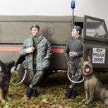 Here is my latest diorama, showing a JU-87B at Caen in France during August 1940. The aircraft is from Italeri, Kubelwagen and 2 figures from Tamiya and the rest of the figures are from ICM. Hope you like it, and all comments welcome
 -
Normandie-Niémen (32092) 1:32 ICM via H G Hannants Ltd The Yak-9 was an evolution of the successful Yak-7 fighter, and was intended to retake the initiative from the Nazis’ new Fw.190 and improved Bf.109s, which it successfully did. Production started in late 1942, and by summer 1943 there were enough in service to make a difference, playing a part in the crucial Kursk battle, thanks to its agility in the denser air at lower altitudes and the heavy armament it carried. It was made in several different variants with diverse intended uses, with the D fitted with additional fuel tanks for longer range, and the DD for longer range still. The Yak-9T was armed with a larger 37 mm Nudelman-Suranov NS-37 cannon firing through the spinner but with only 30 rounds of armour-piercing ammunition carried, which it could fire in two or three round bursts and was intended for use against maritime targets and light armour, where it was quite effective. Careful aim was key of course due to the shortage of ammunition, but when used against another aircraft, a solitary shell strike would rip an opponent to pieces, making the enemy’s day end very badly. Because of the additional weight of the massive gun and its ammo, the cockpit had to be moved aft slightly to counter the change in centre-of-gravity, and various issues reared their heads thanks to the substantial vibrations from firing the cannon. Its standard armament of a 20mm UBS cannon still carried a full complement of 220 rounds as an auxiliary to the main armament. Almost 3,000 were made, and the designers later went one further and installed a 45mm cannon in one variant that had to be fitted with a muzzle brake to counter recoil of crippling proportions that could cause loss of control if fired at slower speeds. In 1942, as part of a stipulation by Charles De Gaulle that Frenchmen should serve on all fronts, a group of French pilots were sent for training in England then onto the Eastern Front to serve with Soviet forces in a squadron that became known as ‘Normandie’. They fought alongside the Soviets in Soviet fighters in several campaigns, and were well-regarded by Stalin, who added the word Niémen to their name in recognition of their participation in the Vilnius Offensive, fighting the battle of the Niémen river. Marcel Lefevre was one of the original pilots and an ace of the squadron, achieving numerous kills, and in later times flying a Yak-9T, although following the end of WWII the pilots and their aircraft were permitted to fly back to France with the Yak-3s they were flying at that time by personal order of Stalin. The Kit This is a reboxing of a brand-new tooling of this capable Soviet fighter from our friends at ICM, and it arrives in one of their standard top-opening boxes with the usual captive inner lid, and an attractive painting of the subject matter on the top. Inside the box are six sprues in grey styrene, a clear sprue in its own bag, a decal sheet and the instructions with colour covers and spot colour throughout, plus colour profiles for the decal option on the rear. Detail is crisp throughout the model, but don’t expect too many rivets to be visible on the exterior, as the metal structure was hidden away inside an outer layer of plywood impregnated with phenolic resin, that is better known in the west by its brand-name Bakelite. Construction begins with the port fuselage, which is adorned with the tubular cockpit framework and has six exhaust stubs on a runner pushed through the slot in the cowling from inside. The tips aren’t hollow, so prepare your pin vice if that bothers you at all. The starboard fuselage half goes through the same process, but adds the structure of the chin intake and its oil radiator cores, then the upper parts of the cockpit are made up, starting with the seat that has a pencil-rolled back cushion, and attaches to the short deck behind it, slotting into the starboard fuselage half along with a bulkhead and the instrument panel, which has several additional parts and a dial decal added along the way. With the completion of the tail-wheel assembly the fuselage can be closed around these sub-assemblies, with an insert added under the chin, while most of the underside is open to the elements at this stage. The kit includes an engine that you can show off or hide away in its basic form of block with cylinder banks that is made from nine parts plus another two for the cannon, which is similarly basic, but as none of it will be seen that hardly matters. The muzzle can be found in the prop assembly if you’re in the mood to drill it out. The basic assembled engine slides into the front of the fuselage with the breech of the cannon slipping through a depression in the bulkhead, after which it can be covered over by two sections of cowling after removing a pair of pips that stand up from the seamline. If you intend to expose the engine however, the power plant is further detailed with an additional twenty parts for the engine itself, and another gaggle for the compartment around it, adding ancillaries, hoses, cowling support structure, the .50cal auxiliary cannon, and a pair of ammo cans for them both that slip into the aft section in front of the cockpit to create a nice replica with plenty of detail. The surround to the cockpit aperture is detailed with the gunsight mount and a piece of clear armoured glass behind the pilot, a small coaming, and the fixed rear canopy part, with the windscreen and its separate clear armoured panel, which is best “glued” on using a clear varnish such as Klear, taking care not to trap any bubbles in between the layers. The opening canopy slides back over the aft section, or you can leave it closed to keep the snow out. In preparation for the wings, a short spar is created with a fluid tank in the centre and a couple of jacks at the ends, then a raised platform is made of the cockpit floor, which has the control column, rudder pedals and a flare pistol fixed in place for later attachment. The lower wing is full-width, and has the central radiator with textured front and rear panels added underneath, and the spar assembly inside, which forms the rear walls of the main gear bays that are joined by several other wall sections and internal ribs that are closed in by adding the upper wing halves. The bay roof is moulded into each wing half, with a little detail visible, but a single ejector-pin mark is visible, and is best dealt with before you glue the assembly together. The ailerons are individual parts that can be posed deflected, then the cockpit floor is glued in and a pair of tapering boxes are inserted in front, although I couldn’t divine their real-world purpose. The wings and fuselage are joined by carefully lowering the latter over the former, taking care not to bend or snap the control stick. The elevators and their fins are each two parts, and these also can be posed deflected if you wish, as can the rudder, which is also made of two parts and glued to the moulded-in fin. The landing gear is a little contrary in that it adds retraction jacks for the struts and inner bay doors first, which are also fitted at this time, with a scrap diagram showing the fine placement of the jack within the bay. The main wheels are each made from two halves with moulded-in hubs, and these are fixed to the axles at the bottom of the struts, with a separate scissor-link and captive bay door on each one, then they mate with the bays on a transverse pivot point, linking to the retraction jacks installed earlier. The model is finished off by adding the clear wingtip lights, gear-down indicator stalks on the wing tops, radio antenna on the fuselage spine, and the propeller assembly, which is made from the moulded-together blades plus front and rear spinner, then the very tip of the 37mm cannon’s barrel, which will need drilling out if you would like a hollow muzzle. The Figure The smallest sprue contains the figure parts, and these should build up into a credible replica of Marcel Lefevre with careful painting. It is broken down into a two-part torso, separate arms and legs, the arms having no hands due to him having his hands in his pockets. His head is also separate with a flat top, and he is wearing a two-part peaked cap, just don’t forget to add the fleecy collar to his jacket before gluing the head in position, or it might be difficult later. In order to paint him, there is a full-page drawing on the rear of the booklet, giving part numbers as well as letter-coded paint suggestions that are converted to ICM, Revell and Tamiya codes on the front of the booklet. Markings There is just the one decal option in this kit, and it has a full page of profiles giving concise locations for the decals and letters showing the colours in reference to a table on the front page that gives names and codes in ICM, Revell and Tamiya brands of paint. From the box you can build the following: Decals are by ICM’s usual partner, which is a guarantee of good registration, sharpness, and colour density, with a thin gloss carrier film cut close to the printed areas. A decal for the instrument panel can be found in the top left of the sheet, with just the dials and white lines defining the sections of the panel, allowing the paint to show through from below. Conclusion A welcome reboxing of this new tooling of this impressive Soviet fighter that should please many a large-scale modeller, with plenty of detail to be had from a relatively simple construction. The bravery of the Normandie-Niéman isn’t as well-known as it perhaps should be, so it’s good that it’s getting some attention. Highly recommended. Available in the UK from importers H G Hannants Ltd. Review sample courtesy of
-
Hello, everybody! Starting with a new model(s)... well actually started with these a while ago, but due to a slow progress haven't yet published it here. The kit is ICM ANZAC Ford Model T 3in1 kit, of which I'm building two. I have a Microdesign PE sets for both of them, a GasPatch Models beautifully made Lewis gun set and one figure from D-Day Miniature Studio for now. There is a small diorama setting with those two vehicles and a few more figures in my mind. Here are all the goodies I have at hand. The mudguards and the frame are molded into one piece and have quite a few KO marks underneath that will not be visible really, but I filled these anyway. One thing I wanted to try is to make the front axle movable at least on one of the vehicles to make the setting more lively. It required some on-the-edge surgery, but turned out to be not as hard as one might expect, As both of the kits have double details for the axle and the steering parts it made it a lot easier to do. Underneath I added brake linkages and rods. Again - won't be much visible, but an the other hand, why not. To date I'm a bit more than on a halfway there with the engine compartment, that included some added wiring and replaced piping. Here is the thing with the details dry-fitted. And with another one that is disassembled. Cheers! Kristjan
-
 At the Moscow "Мир детства 2021" expo, ICM has announced a 1/32nd family of Yakovlev Yak-9 onwards 2022 Source: AlexGRD V.P.
 -
A usually reliable russian source announces ICM is to release in 2017 a 1/32nd Polikarpov I-16 kit. To be followed. Source: http://scalemodels.ru/news/10678-anons-ICM-1-48-He-111H3.html For the record a 1/48th I-16 type 24 kit is expected by ICM in December 2016 (link). V.P.
-
WWII Japanese Aviation Acrylic Paint Set (3021) ICM via H G Hannants Ltd ICM have recently released their own brand of acrylic paints on the market, and are creating some kit specific sets to go with their major releases, of which this is one. The set arrives in a cardboard box with six screw-capped bottles inside, each containing 12ml of paint. The bottles are clear Polypropylene, and are capped with cylindrical tops with knurled sides, and a one-time security seal that you break on first opening. A label on the side gives you basic information about the colour and code, a little information regarding application in English and Ukrainian and a bar-code. This set provides the major colours to assist you in painting your Ki-21-Ib Sally in 1:72 from ICM themselves as well as plenty of other kits from ICM and other manufacturers, and you will find the following colours in the box: 1063 Green-Grey 1023 Aluminium 1025 Natural Steel 1062 British Khaki 1073 4BO Green 2002 Satin Varnish The paint is thick in the bottle, with plenty of headroom between the surface of the paint and the lip of the neck. I dropped a glass stirring ball into each bottle, and they took a few seconds to disappear beneath the surface, indicating their viscosity. During testing, I used Ultimate Acrylic Thinners to dilute the paint to spray through my Gunze PS770 airbrush, which has a 0.18 needle chucked in. The paint dilutes well once it has been mixed thoroughly, and sprays well through my airbrush, which has a smaller than usual needle that is a good test of the finesse of the pigment grind of any brand, some of which don’t spray very well though anything less than a 0.3mm needle. There were no problems with blockages at all, and the coverage was excellent after my usual ad hoc dilution method, which was probably nowhere near the 40-60% thinners or water that’s suggested on the pack. Apart from the varnish, the other paints all dry to a matt finish. In past tests, the Satin Varnish worked very well diluted with water, sprayed over the spoons that were also partially taped up to perform two functions at once. The satin patina that resulted is exactly what was expected, and the tape lifted no paint at all, despite my best efforts to do so. Bear in mind that the spoons were prepped by a buff with a very fine sanding sponge to give them the best chance of adhesion. Using a brush, the colours cover well two coats with minimal brush marks visible. Conclusion The paints were excellent through the airbrush with nothing in the way of drama during the testing process, including the Oily Steel and Satin Varnish. The colours also brushed out very well, as did the varnish. There is a little less paint in the bottles than some brands, but a shade more than others, so it’s about average. That is more than offset by the very reasonable price they’re asking for the set, even at RRP. Highly recommended. Available in the UK from importers H G Hannants Ltd. Review sample courtesy of
-
Ki-21-Ib Sally (72203) 1:72 ICM via H G Hannants Ltd The Sally, as she was known by the Allies during WWII was a heavy bomber designed by Mitsubishi as a replacement for the Ki-20, in competition with Nakajima, who although they lost out on the design of the aircraft, were given the contract for the power plants, as their HA-5 engines were found to be superior to Mitsubishi’s offering originally installed. A small number of airframes were also built by Nakajima too, with a total of just over 2,000 built between them. It first flew in 1936 and was intended for long-range bombing missions against Soviet and Chinese opponents, first entering service in 1938 in operations against China. Initial experience showed that the design was lacking in some respects, extending to the crucial oxygen system that was found to be unreliable. The Ib was intended to address most of the issues, including the lack of armament and changes to the flying surfaces. It also had a remote tail gun installation, and could mount an additional fuel tank for extreme range missions. The type was pretty much obsolete by 1940, and mounting losses prompted the type’s withdrawal from front line service, and sale of some of the airframes to friendly nations. Uses were still found for the type with the Japanese forces however, and the remaining aircraft were used until the end of the war as cargo transports, trainers, troop transports and communications hacks. The later variants had improved engine performance with Mitsubishi units, some with alterations to the greenhouse behind the cockpit, which was changed to a turret on some, and removed entirely on transport variants. The Kit This is a brand-new tool from ICM, who continue to produce new kits despite the difficult circumstances in their home country. The kit arrives in a shallow top-opening box that has a captive top flap on the bottom tray. Inside are six sprues in grey styrene, a clear sprue in a separate bag, decal sheet and the instruction booklet, which is printed in colour with colour profiles on the back pages. Detail is well up to modern standards, and extends to ribbing on the interior of the fuselage, full representation of the engines and a nice cockpit, plus a set of crystal clear glazing parts. Construction begins with the fuselage halves, which have the armed Ib tail added to the rear, a lozenge-shaped detail insert to make the wing root recess flush, and the side windows, plus an equipment insert in the cockpit area, and a line of trunking that extends from the trailing edge of the wing to the tail. The cockpit floor is a long part, with a recessed front end for the flight crew, detailed by adding the rudder pedals for the pilot, and the two seats, which both have separate seat cushions. The twin ‘bow tie’ control columns are inserted into the floor in front of the seats, and near the rear of the floor are two large tanks that attach on pins. The assembly is inserted into the starboard side of the fuselage, and has a bulkhead fixed just in front of the crew steps under the mid-fuselage greenhouse. The front bulkhead has a small circular seat glued to the side of the fuselage and additional details with instrument decals, a choice of two clear chin inserts with an instrument panel, gun mount and a rack of bottles added to it during installation, with a choice of two types of machine gun for the belly window that has two spare mags nearby. The port fuselage is prepared with tail, wing insert and windows, plus ammo cans and forward fuselage details, more racks of oxygen bottles and a side-mounted machine gun. The fuselage can be closed around the cockpit after adding the main instrument panel, which has a centre throttle quadrant and dial decals added beforehand. The mid-upper gunner’s suspended seat is also inserted into holes, but can probably be inserted after gluing the fuselage halves together by flexing the support struts. His twin machine guns are added to a mount on a bracket, with a pair of magazines on top, after which it is fitted into the insert that is then glued into the opening in the fuselage behind the main canopy. The main canopy and greenhouse gunner’s canopy are fixed on top of the fuselage along with the nose glazing, which has a choice of two types of machine gun inserted from the inside. The tail begins by adding the elevator fins, which have separate flying surfaces and rudder panel, then the wings are prepared by inserting a two-part bay in each one before joining the upper and lower halves together, adding the ailerons and landing lights in the leading edges. They are then glued onto the wing root fairings on the fuselage, which have a lip to improve fit and joint strength. The wheels are installed under the wings before the engines and lower cowling are made up, starting with the tail-wheel in its yoke, and then adding the two-part wheels to the H-frame main gear, which has a support frame fitted to the front, and a long yoke with mudguard that links the strut lower to the back of the bay. Four small parts are fixed to the wing inside the bays, and the lower cowlings are made up out of two halves plus a round bulkhead, and a pair of intakes top and bottom, then sliding the lower nacelle over the completed wheels and mating the edges with the recessed lip of the lower wing. The engines are built-up on bulkheads with the cooling flaps moulded-in, a separate exhaust stack underneath, and a depiction of both cylinder banks, plus the front bell-housing with push-rods, hiding the prop axle inside without glue so that the props can spin later. The finished engines are covered by two cowling halves and a separate lip, gluing them to the front of the nacelles and finishing them off by adding the three-bladed prop and separate spinner. The model is completed by installing an antenna post and D/F loop over the canopy, and a curious-looking cranked pitot probe in the leading edge of the port wing. Markings There are four options on the decal sheet, all in light green-grey, differentiated by their unit markings. From the box you can build one of the following: 60th Sentai, China, Summer 1940 60th Sentai, 3rd Chutai, China, Late 1940 58th Sentai, Harbin, December 1940 105 Kyoiku Hiko Sentai, Hamamatsu, Presumably 1942 Decals are by ICM’s usual partner, which is a guarantee of good registration, sharpness, and colour density, with a thin gloss carrier film cut close to the printed areas. As is common now with ICM kits, there is a page of the instruction booklet devoted to the masking of the canopy, using the printed shapes on the right of the page and the diagrams on the left to create your own masks if you wish. It goes up to 130 thanks to the extensive greenhouse glazing. Conclusion A nicely detailed new tooling of this short-lived (in front line service at least) heavy bomber, which should put older toolings from other manufacturers out to pasture. Highly recommended. Available in the UK from importers H G Hannants Ltd. Review sample courtesy of
-
The Game – Square (16210) 1:16 ICM via H G Hannants Ltd The TV series ‘The Squid Game’ has been a massive hit worldwide, but I’ll be honest and tell you that I’ve still not seen it. It’s a South Korean series consisting of 10 episodes that has become a blockbuster on Netflix, that’s insanely popular with Western audiences despite the language barrier, as most of us don’t speak Korean – thank goodness for dubs. It’s about a TV game show that involves hundreds of impoverished players competing in childish games for a huge cash prize that is paid to the ultimate winner, totalling 45.6 billion ₩ (pronounced Won) (that’s £28,664.54 or $34,810.22 for the Brits and Americans at today’s exchange rates), but the caveat is that these games are deadly. You’re going to die if you lose. Each episode is 55 minutes long, and I picked it up out of curiosity when the first kit arrived, but still haven’t watched it yet, so I still don’t know what all the fuss is about. The contestants all wear a loose-fitting jumpsuit in red to hide their gender and identity, which is further hidden by the black full-face masks that they wear, giving the impression of an ant face, which was deliberate according to the IMDb trivia section. Even the staff wear the same gear, but on the ‘forehead’ of the staff masks are simple white symbols in the shape of a circle, square, or triangle - the reason for which I don’t yet know. If you’re wondering why it’s called The Squid Game, it’s because the player board is in the shape of a squid roughly scratched into the ground. The Kit This figure arrives in a slim top-opening box with a captive inner lid on the tray, and inside are four sprues in grey styrene, and three in black styrene, a small decal sheet, and the glossy instruction sheet that is printed in colour. The final item in the box is a glossy colour print of the box top art, which you can stick on your wall or not. It’s a simple kit because it’s a figure dressed in a jumpsuit, but it is well sculpted and as detailed as we’ve come to expect from ICM. Construction is carried out according to the same diagram as the painting guide, which uses the same drawings to give paint and part numbers for simplicity. The figure has a face with lower half covered by a mask, even though the main mask tends to obscure all the detail, but there it is, so if you wanted to adapt your figure to have the mask off, you can do so by removing the strap with a motor tool or old-fashioned sanding stick. The figure is made up from sixteen parts in grey, with separate legs, arms, a two-part torso, two-part hood, a well-detailed head that is wearing a half mask, hands, separate cargo pockets with keyed attachment point, and a single black mask that fixes to the front of the head, which has the retaining strap moulded into it. This figure is armed with a revolver that is moulded into the right hand, and it is aimed diagonally upward as if starting a race, or as is more likely, vaguely threatening someone. The revolver has an empty holster included on the sprues, but there is also another part that has the gun moulded into a holster, as it’s the same sprue used for other figures. The base is moulded in black styrene, and has a choice of four different surface textures for the top and a flat base for the bottom. The choices comprise a flat asphalt surface plus three styles of cobble or paving stones, and is a constant theme of ICM’s 1:16 series of figures, so they’ll all match. Markings The decal sheet includes one square decal for the character’s forehead, and you are advised to paint the jumpsuit blood red, with rubber black (dark grey) and black for boots and other accessories. You can change the colour of the suit to your whim if you know what you’re doing and have watched the series, and some simple masks or decal strip could be used to create the other shapes if you prefer this pose for other characters, or wanted to create a new one for your own (as yet imaginary) season 2. Conclusion A nice figure that hits near the height of popularity of the series, according to my 12-year-old son who still gets bombarded by spoilers for it at school. You can use it as intended, or tinker with it to portray other players, staff, or even go totally off-piste and use it in another situation entirely. Highly recommended. Available in the UK from importers H G Hannants Ltd. Review sample courtesy of
-
 Time for a classic two-mot. To avoid the usual silver, olive and black schemes, my dad and I decided to go for a more colourful Latin American one. Although the Chilean Invaders were officially retired in March 1973, "840" and "846" were reactivated in September 1973 due to the military coup and were used for surveillance and patrol flights over the whole country. Gonna use one of the new ICM kits with Vespa Model Kits decals. The latter ones are from Lima/Peru, printed by Fantasy Printshop in the UK. DSC_0001 by grimreaper110, auf Flickr DSC_0002 by grimreaper110, auf Flickr DSC_0003 by grimreaper110, auf Flickr already started with the cockpit DSC_0004 by grimreaper110, auf Flickr
 -
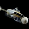
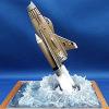
Back again with another recently wrapped project, the ICM 1/72 'Ghost of Kyiv' MiG-29. Finished this months ago, but forgot to add the wingtip nav lights. Finish was also a little too glossy, so I slapped some liquid masking on the canopy and nose sensor and sprayed it down with some satin varnish. Had this idea in mind almost as soon as I saw the kit, and while the kit itself was a little basic and required a fair amount of filling and sanding to get right, and the decals were incredibly frustrating (being far too thin and flimsy, and near instantly sticking themselves) requiring that I try to duplicate the failed ones with Tamiya masking, I'm happy with the end result. Also a bit of a disaster with the one decal that didn't decide to stick down instantly in the right side intake number, which my thumb apparently touched at some point and bunched up. Decal was beyond use, so I had to hand paint the number back in 😬 Only major modification I made to the build itself was closing the upper louvres by moulding some Miliput. Model didn't have that as an option, but the aircraft close those in flight and open up the main intakes. Added a pilot figure, pulled from my Bandai X-Wing kit where I didn't use the rebel pilot in the seated position. Thankful I had him, because I could not find any aftermarket 1/72 pilots that were suitable (certainly not reasonably priced from what I can recall). Modded him up as best I could and in he went. Second attempt at mounting a model aircraft in flight, and the first attempting to replicate a fired missile. Smoke effect wasn't brilliant at first, but then I saturated the cotton wool (superglued around a wire) with diluted modpodge and was able to shape it into something tighter. Overall happy with how it turned out, even if I couldn't get that field to go brighter no matter how many times I tried Whole thing has a display cover as well. Anyway, enjoy As always, thanks for looking Gaz
- 10 replies
-
- 25
-

-
#25/2022 Next Latin American subject finished by my dad. ICM A-26B-15 kit (which includes also the late canopy), Vespa Model Kits decals (based in Peru, printed by Fantasy Printshop in the UK). Upper turret hole closed with plastic sheet, removed lower turret closed panel taken from the ICM B-26C-50 kit. Wheels with correct rims and tread for this aircraft taken from a Revell Invader kit, horseshue antenna on the rear belly taken from a Monogram C-47 kit. Seatbelts from the sparesbox, added a scratchbuilt external gunsight, painted with Gunze H314 FS35622 , Tamiya XF-57 Buff and Gunze H309 FS34079. Build thread here https://www.britmodeller.com/forums/index.php?/topic/235116023-coup-d’état148-douglas-b-26d-invader-fuerza-aérea-de-chile/ Chile received its first 10 Invaders in late 1954. All were B-26C models with the glass nose, painted in black, serving with Grupo de Aviacion No. 8. In 1957, 1958 and 1960, further Invaders were delivered by the US, making it 38 in total. Some of them were TB-26 versions with a solid nose for training and target tug duties. In 1963, the FACh received reports from Invaders in Vietnam, losing wing parts due to material fatigue. So from 1964 to 1965, the remaining 18 Chilean Invaders were flown to Panama and underwent the wing-spar program. In 1966, the FACh wanted more punch for their Invaders and it was decided to fit the now remaining 17 aircraft with a 6-gun nose, but the US only delivered 8 conversion kits. Ventral and dorsal gun turrets were removed too and a new two-tone camo applied. These eight Invaders were now called B-26D. Due to corrosion, lack of spareparts and no support, the last remaining five FACh Invaders were retired in January 1973, the last official flight was on March 21st 1973, the 43rd anniversary of the FACh. During the military coup in September 1973, "840" and "846" were reactivated and flew patrol and surveillence missions over the whole country until January 1974. DSC_0001 by grimreaper110, auf Flickr DSC_0002 by grimreaper110, auf Flickr DSC_0003 by grimreaper110, auf Flickr DSC_0004 by grimreaper110, auf Flickr DSC_0005 by grimreaper110, auf Flickr DSC_0006 by grimreaper110, auf Flickr DSC_0007 by grimreaper110, auf Flickr DSC_0009 by grimreaper110, auf Flickr DSC_0010 by grimreaper110, auf Flickr DSC_0011 by grimreaper110, auf Flickr DSC_0012 by grimreaper110, auf Flickr DSC_0013 by grimreaper110, auf Flickr DSC_0014 by grimreaper110, auf Flickr DSC_0001 by grimreaper110, auf Flickr DSC_0016 by grimreaper110, auf Flickr DSC_0017 by grimreaper110, auf Flickr DSC_0019 by grimreaper110, auf Flickr DSC_0020 by grimreaper110, auf Flickr DSC_0021 by grimreaper110, auf Flickr DSC_0022 by grimreaper110, auf Flickr DSC_0002 by grimreaper110, auf Flickr DSC_0024 by grimreaper110, auf Flickr
-
Hi Now my 5th Ju-88 is ready. The second from ICM. Before that it was Dragon and Revell. Regarding the kit: Relatively large compromises have to be made in terms of accuracy compared to the origin. This primarily affects the cockpit, with the flat floor instead of the massive height offset. This is linked to a few details in the cockpit that made me shake my head. The additional control stick in position, the additional control stick, which was intended for the bombardier, is only installed when approaching the target, otherwise it is fixed to the right side wall. The device for storing the boarding ladder on the rear bulkhead under the radio equipment is missing! The A-4 variant is missing all ammo boxes. The ammunition feed and the sleeve hoses are also missing. Therefore I did not install the weapons. What is still missing is the large bulkhead on the large cockpit hood, not even Eduard has it with him. General: The injection molded parts just don't fit well. Some parts are warped, the wing connections have a tolerance problem with the pins and holes. They're really annoying. Many gluing areas are beveled, so that in the end there is an gluing line instead of an gluing area. So it will loosen easily! When installing the engine nacelles, the designer obviously neglected some of the geometry. The front tenons of the inside and outside nacelle would have to be chamfered so that a reasonable prefabrication of the assembly group is possible. The quality: Of the injection molded parts themselves can best be observed with small parts. There is hardly an antenna or pitot tube that does not break. Brittleness is present in smal long thin parts. Some components have so much internal stress that maximum force is required to join them. Classic example is the great pulpit. The nose pulpit has a typical tolerance problem. Tongues on upper part reach too far down left and right for lack of fit. Rework required. Especially on a fuselage front part, which consists of three or four parts, a complete fitting test beforehand is hardly possible. About the model: This A-4 has an interesting paint job that deviates from the norm. The aircraft is from KG 54 Totenkopf. Operative in Brindisi in Italy around 1943. I will make the aircraft from KG 54 Totenkopf. Operative in Brindisi in Italy around 1943. Brindisi is in the middle of the heel of the Italian boot at the eastern coast. In this area there occurred one of the biggest environmental pollutions. Here is the link: https://en.wikipedia.org/wiki/SS_John_Harvey By the way, the scribbling I used a pen. First time. Acrylic empty pen from Montana. My WIP: Well, so have a look on the model now: Happy modelling
- 13 replies
-
- 37
-
-

-
Gotha Go.242A (48226) 1:48 ICM via H G Hannants Ltd Germany broke new ground in WWII in the successful use of Paratroop landings in gliders that met with some initial successes, although that method of delivering soldiers and materiel hasn’t seen much use since the end of WWII, possibly following the experiences of the Allies later in the war and around D-Day. Gotha created the small DFS 230 that was used by Fallschirmjager units during the early part of the war, and the RLM subsequently issued a specification for a larger glider that could carry 20 fully equipped troops into action, or alternatively bring equipment of an equivalent weight to the battle. Gotha’s offering was a simple tapered box on wings, but with a twin-tail boom that allowed the cargo version to unload from the rear using a simple flip-up rear fuselage, and later the troop carrier could also unload from the rear with the addition of new doors. The type entered service soon after its initial flight in 1941, with over 1,500 manufactured in various guises. The initial A series was split into troop and cargo types, with the following B series being improved from experience and sporting upgraded landing gear, plus double rear doors for faster troop exit. A further C series was intended for water landings using a boat-shaped hull to carry explosive-laden small boats to maritime targets, although that never reached service. Gotha later added engines in nacelles that extended the twin booms past the leading edge of the wings, allowing it to get aloft under its own power, rather than being towed by a Heinkel He.111 or an adapted Stuka, but take-off was marginal with a heavy load, so RATO bottles were developed to give the aircraft an extra boost. The Kit This is a minor re-tool of their recent kit of this boxy glider, and one of a number of variants, hopefully including the powered option. Despite their difficulties at the moment, ICM are still working hard to keep on producing kits, and our collective hats have to go off to them for that. The kit arrives in a top-opening box that has the Ukrainian flag emblazoned in the top right corner, and a painting showing the aircraft from the side with its landing gear clearly visible. The outer lid is extremely tight, and if you can get it off the usual captive inner lid is exposed, with eight sprues in grey styrene, one of clear parts, the instruction booklet in spot colour, and a long narrow decal sheet. The first thing that’s evident on perusal of the sprues is that the aircraft is that the wingspan is really quite wide, and the designers at ICM have put a lot of effort into the detail that’s moulded-into the model, especially the sections that are fabric over a tubular framework. Construction begins with the large floor space, which is made up from the fabric outer skin with visible ribbing, onto which the floor surface added in two sections, after drilling a number of 1mm holes in the skin first. The forward section is then enclosed by a tubular framework that stops at the centre bulkhead, which also has short spars moulded-in, with a bulkhead between the passenger and pilot sections. The twenty passenger seats are each made from horizontal and vertical sections that are then arranged into two rows of 10 and are fitted out with diagonal braces that mate with the rear legs, plus a length of top brackets that allow the seats to stand clear of the wall. Both rows are glued into the passenger compartment either side of the central spar, and a triangular section of framework is attached to the aft section of the area, following which the side walls are made up from two parts each, and here the A variant had a different layout to the rear windows, that are applied from the inside. The walls are fixed to the floor assembly along with the roof once the cockpit is made up. This isn’t a training variant, but the controls are still duplicated on both sides of the cockpit for redundancy, starting with a well-detailed pair of rudder pedals that each comprise of four parts. The control column differs between stations, with the pilot having a two-part right-angle column with separate yoke, while the co-pilot has a straight stick for when he needs to take over, for example when landing under fire and the pilot is incapacitated. The seats differ too, as the pilot has a sturdier five-part seat that has an adjustment wheel, while the co-pilot has a simple two-part affair. These are all inserted onto a cockpit floor that is placed within the front of the fuselage at the time when the sides and roof are both added with a single tube bracing the top of the diagonal rear divide. The cockpit surround is incomplete at this stage, having the nose added along with a simple instrument panel on a pair of supports fitted and dial decal applied, then underneath a clear window is inserted beneath the co-pilot’s feet, plus two panels of side glazing and a single windscreen part that has an optional 0.8mm hole drilled in it before fitting if you are mounting the guns. Take it easy if you decide that’s the option for you, as clear styrene is much easier to damage because of its brittle nature. Light pressure and plenty of patience is the way to go. The boarding ladders are cut away from the underside of the fuselage, as the earlier crew were expected to leap up athletically. The wings of the 242 are necessarily long for lift, as once the towing aircraft cuts it loose, the only way is down, so a long glide slope is an absolute necessity. The wings are each moulded as top and bottom skins, which have some lovely ribbing and other details moulded-in as you can see above, and have the flying surfaces as separate sub-assemblies of two parts each. Once the halves are joined, they have the front fairings of the booms added top and bottom, then have the two flap sections and long ailerons slotted into the trailing edges. This is repeated twice in mirror-image of course, and the two wings are slotted onto their projecting spar sections, taking care to put them on with the leading edges and canopy pointing in the same direction. A pair of supports are added underneath in recessed sockets, although I’d be tempted to leave those off until after main painting was complete so they don’t get damaged. The aft section of the fuselage is missing at this stage, giving it the look of a “ute”, but this part is next to be assembled. The tapering sides have windows inserted from inside and the internal framework added, then they are spaced apart by three more framework sections, after which the lower part with window, internal floor with steps, and roof with framework and observation window (the reason for the steps) added, to be finished off with a transparent end cap giving even better field of view, just in case they’re being stalked by a fighter from behind. The door pivots upward between the booms, and can either be glued closed, or propped open with five supports holding it at the correct angle. Again, if you are using the self-defence armament, another 0.8mm hole needs to be drilled near the hatch in the roof of the aft section. The booms are simple and made from two parts each, with separate rudders and a single two-part elevator panel with separate flying surface. The instructions show the completed assembly being offered up to the rear of the model, but it may be more sensible to glue one boom in place first, then add the other with the elevator once the glue is set on the first boom. A number of actuators and mass balances are added all around the flying surfaces, but first the landing gear is made, based on a single axle that is mounted on an extended A-frame that runs under the fuselage, and sports a two-part wheel at each end. The rest of the airframe is supported by a trio of sprung skids, the rear two with tiny wheels on the very end, the forward one having a hook on the tip. The final parts are used for two optional self-defence machine guns that are fixed to the windscreen and in front of the observation window in the aft section of the fuselage, both having a moulded-in concertina dump bag for the spent brass, and a double C-shaped ‘snail’ mag draped over the breech. Markings There are four decal options on the sheet, three of which are very similar and sporting yellow wingtips with a tail band in the same colour, while the other is over-painted with a wavy brown camouflage pattern. ICM have also included a printed template for masking the copious glazing that’s present on this aircraft, which should come in handy, and save some hassle, even if you’re confident masking canopies yourself. From the box you can build one of the following: Gotha Go 242A, Mediterranean theatre of operations, 1942 Gotha Go 242A, presumably Eastern Front, summer 1942 Gotha Go 242A, southern section of the Eastern Front, 1942 Gotha Go 242A, Eastern Front, winter 1943 Decals are by ICM’s usual partner, which is a guarantee of good registration, sharpness and colour density, with a thin gloss carrier film cut close to the printed areas. Conclusion The Go.242 is a quirky-looking box that appeals due to many factors, including the detail being excellent, so it’s a big thumbs up for a kit that has been produced under very difficult circumstances. Very highly recommended. Available in the UK from importers H G Hannants Ltd. Review sample courtesy of
-
In 2019 ICM is to release a new tool family of A/-B-26B/C Invader kits: - ref. 48281 - Douglas B-26B-50 Invader, Korean War American Bomber - released Source: https://www.hannants.co.uk/product/ICM48281 - ref. 48282 - Douglas A-26B-15 Invader - released Source: https://www.hannants.co.uk/product/ICM48282 Dedicated decals by ICM: - ref. D48001 - Douglas A-26B/C Invader (WWII) - released Source: https://www.hannants.co.uk/product/ICMD48001 - ref. D48002 - Douglas B-26B/C Invader (Korean War) - released Source: https://www.hannants.co.uk/product/ICMD48002 V.P.
-
At the Moscow "Мир детства 2021" expo, ICM has announced a 1/72nd family of Mikoyan-Gurevich MiG-23/-27 Flogger from 2022 Source: AlexGRD V.P.
- 49 replies
-
- 11
-
-
-
For many years I've been saying I've wanted a 1:48 Beaufort because for some reason I've always liked the look of this aircraft! Call me weird, but there something about this hump-backed beast that I like! So a couple of months ago I was astonisehd to discover that ICM had just released a kit! Thankfully the IPMS Abingdon show was a couple days later and I managed to get one! I also got the 3D instrument 'decals' from Kits-world, but I think its fair to say I won't be using them again as I can't honestly say I was that impressed. The build was interesting and had it challenges, particularly around the fitting of the engine cowlings! My advise is do NOT follow the sequence in the instructions, fitting the propellers to the engines, then fitting them to the wings and then trying to assemble the cowlings around them. I ended up having to chop off the props again and assemble the cowlings as a single piece and fit them. The joint is not easy to get right and is VERY visible on the finished model if not done right! Anyway the finished pic... I'm really pleased with how it came out in the end after almost ruining it at the varnish stage!!! Now I need to build a Beaufighter and a Blenheim...
-
Hello! New items from Ukrainian manufacturers Mikro-Mir NEW 48-020 DH.112 Venom De Havilland fighter-bomber scale 1/48 35-027 Mikro Mir Dictator 13 inch Seacoast Mortar scale 1/35 ICM NEW DS7203 Soviet military airfield 1980s 72203 Ki-21-Ib Sally 48304 OV-10A Bronco US Navy 35136 Unimog 404 S “Koffer” 35716 s.Gr.W.34 WWII German mortar 32117 Pilots of the Soviet Air Force 1943-1945 New items from Ukrainian manufacturers https://amarket-model.com/ https://www.facebook.com/people/A-market-scale-model
-
- 2
-
-
- Amarket-model.com
- Mikro Mir
- (and 1 more)
-
Hallo This is now my second Ju-88 from ICM. I built before my A-5 version. I will make the aircraft from KG 54 Totenkopf. Operative in Brindisi in Italy around 1943. I will make the aircraft from KG 54 Totenkopf. Operative in Brindisi in Italy around 1943. Brindisi is in the middle of the heel of the Italian boot at the eastern coast. In this area there occurred one of the biggest environmental pollutions. Here is the link: https://en.wikipedia.org/wiki/SS_John_Harvey From Wiki German edition translated / English version of Wiki this subject is omitted! The most momentous air raid occurred on the night of December 3rd, when II. Gruppe, together with other squadrons, attacked the port of Bari. 18 ships with a total of 71,566 GRT and 38,000 t of cargo were destroyed. The Liberty-class freighter SS John Harvey exploded with a cargo of 2,000 AN-M47 bombs filled with a total of 480 tons of mustard gas. 1000 soldiers and civilians perished. The Allies concealed the consequences of the mustard gas on those affected. The camo is interesting, a good difference to the splinter scheme of my A-5. I will use Montex masks. Which individual a/c I will do, my options are from the same squadron LR or LA. Now, to face the main issues on this kit. The cockpit is wrong. We face here a flat floor, which is not so at all in reality. We have three possibilities. · To leave it as it is · To use a resin aftermarket cockpit · Or to make some scratch I decided after my experience with the resin from AIMS for the third choice. To avoid fitting troubles with the glass and fitting problems with the Bola. (Boden Lafette) The downward gondola. To improve the fuselage stiffness close to the wings I made one bulkhead in scratch. Before continuing with the build I emptied one sprue and did the main gear already. One error in the instruction is obvious. Look at the picture 48! The gear main mount is too small in gauge. About 1 mm. I had this problem when inserting the gear on my A-5 already. In this kit the difference is more. So I increased the gauge with steel wire to the proper distance as required. Meanwhile I did also the wings. Assembling, grinding, and filling. I inserted the landing light, after spraying the backside with Aluminum. At the wing tips I drilled holes, since this kit omitted the position lights in red and green. Well, it is done! So far this day. Happy modelling
-
ICM is to release an 1:350 Kriegsfischkutter in December. The Kriegsfischkutter (or KFK for short - translates into war fishing vessel) was the most common German warship in WW2. Built by yards in Germany and occupied Europe as well as in friendly Sweden (45+ hulls), the 600+ vessels were found pretty much everywhere the Kriegsmarine had a presence. It was basically a heavily armed fishing vessel used for ASW, convoy escort, mine sweeper, patrol craft, rescue vessel and light transport. After WW2, some were converted back to fishing vessels and coastal transports while others were taken over by the navies in liberated Europe. For instance, the Norwegian coastal artillery used a couple as transports for quite some time. References: https://de.wikipedia.org/wiki/Kriegsfischkutter https://de.wikipedia.org/wiki/Liste_der_Kriegsfischkutter https://icm.com.ua/2022/11/17/soon-on-sale-kfk-kriegsfischkutter/ Sources: https://www.facebook.com/ibgmodels/posts/pfbid034s9i5nFSGLyQmHiteuHsvjUx6YNjjW7Gei9WNvjhLRewDPXhd4YhkCKEQP3R5iTUl https://icm.com.ua/ship/kfk-kriegsfischkutter-3/
-
Forward Base (48303) OV-10A Bronco, AH-1G Cobra, US Pilots & Ground Crew 1:48 ICM via H G Hannants Ltd During the protracted period of the Vietnam war, the US Air Force used the OV-10A Bronco as Forward Air Control (FAC) and ground attack aircraft, so they had to be relatively close to the front to maximise loiter-time, often sharing a Forward Base with attack helicopters such as the AH-1G Cobra for similar reasons. These bases were crewed by mechanics for maintenance of the aircraft, as well as the usual force protection, administration staff, cooks & bottle-washers but in smaller numbers due to the risks of being closer to the enemy, who could melt into the jungle just as quickly as they would pop out with guns blazing. The Set This boxed set contains a total of two kits and two figure sets in a single box that is barely any bigger than a standard one, despite the quantity of plastic within. Each kit is separately bagged, and the instruction booklets/sheets have been corralled in a card folder, and have their decal sheets hidden between the pages. Incidentally, the weapons decals were missing from my boxing, but we have a photos from a previous boxing that give you the idea of what will be in your box. On with the motley! AH-1G Cobra This is a recent tool from ICM and brings us a long-overdue update to some of the older kits of the type on the market. This edition depicts Vietnam airframes, and inside the bag are eleven sprues in various sizes in grey styrene, a large clear sprue with a choice of canopies for upcoming versions, a decal sheet and their usual glossy A4 instruction booklet with spot colour throughout, and colour profiles of the decal options in the rear. There are a number of peach-coloured rectangles on the sprue diagrams, as they have been tooled with future boxings in mind, so after you’re done building it, you will likely have a number parts left over. I’d also recommend checking the sprues for parts that have come off the runners during shipping, as a fair few were loose in the initial boxing, so don’t go tossing the bag in the recycling before you’ve checked for stragglers. Detail is excellent, as we’ve come to expect from ICM, especially in the cockpit, the exterior surface and the rotors, and the instruction booklet takes you through the build process with colour and scrap diagrams used to clarify the process. Construction begins with the cockpit, which will be highly visible through the crystal-clear canopy parts, and this starts with the twin tub (no, not a 60s washing machine), into which the quilted rear bulkhead, twin pilot controls and tail rotor pedals are fitted, followed closely by a pair of instrument panels with decals and deep coamings to reduce glare coming though the big canopy panes. The panels are different for front and rear crew, but their seats are very similar with armoured wings and sides on the cushioned seat, made of four parts each. Remarkably quickly we’re starting prep of the fuselage halves by drilling out a number of holes, adding the nose cone and tail fin, taking care to align them carefully as well as choosing the right one, as there are two tails on the sprues. The rotor-head is installed on a flat plate, allowing the head to rotate if you’re careful with the glue, then it is inserted into the fuselage along with the cockpit tub and the short exhaust trunk, closing it up and leaving it to set up so you can deal with the seams, and fill a small hole near the rotor head. With that done, the cockpit is outfitted with more armour panels on the internal sidewalls and on the port side exterior, adding a number of appliqué panels in two parts. The underside of the fuselage is bereft of detail until you add the two armoured panels under the cockpit, and glue an insert into the hole in the underside after drilling out a pair of holes from within for one variant. Two main intakes above that slot into recesses on the fuselage sides. The Cobra has wings! Little ones that are essentially weapons carriers, and these both have a separate wingtip and root mounted ammo pod under each one, the port pod later feeding the M35 gatling gun and a link between the starboard and port pods. At the rear you have a choice of two styles of tail stabilisers, one covered in rivets, the other nice and smooth. Speaking of the tail, the boom is covered in nicely rendered raised rivets, as is correct for the type. Two pylons attach to the underside of the winglets, one in the tip, another fitting into two holes. The short circular exhaust ring is installed at the open end of the trunking, with two small strengthening plates just underneath them. With the fuselage flipped on its back, the nose turret is next, with a pair of inserts added into the main turret part, and a 7.62mm gatling gun in one aperture, plus a 40mm grenade launcher in the other that you’ll need to drill out the muzzles on if you feel the urge. The very tip of the nose cone is separate, and has a pitot probe added near the top, then it’s time to add a few antennae and clear lights, plus the BIG gun, which has a separate hollow muzzle part, ammo feed and two other small parts, which is suspended from the underside of the port winglet, and linked to the ammo pod as mentioned earlier. The skids with the thicker supports and a whip-like safety skid under the tail finish off the main fuselage for now, after which the rotating parts are made. The Cobra had a twin-blade tail rotor that slots straight into a hole in the top of the tail fin, with an M-shaped control mechanism fixed to the centre, and a couple of clear parts added to fairings nearby. The main rotor sits on a chunky axle, over which a faceted washer slides, that is joined to the base by a pair of actuators. The two main blades are moulded as a single item, and are first detailed with additional parts before they are glued to the top of the drive-shaft, and supported by a pair of long control rods linked to the blades to adjust their incidence. A scrap diagram shows the various parts in grey to help you get everything correctly aligned. It is lowered into the top fairing later and glued into place, but first the canopy is completed. The Cobra’s canopy opens on different sides for each crew member, and has the long narrow top is fixed first, with the windscreen moulded-in. A small instrument is glued to the side of the screen, 3.5mm up from the bottom, after which it is glued onto the fuselage. The pilots exit from opposite sides, so after the sloped starboard section and port rear section are fixed in place, the two openers can be mounted in the open position and supported by props to achieve the correct angle for them. In addition to guns the Cobra could carry rocket pods, and two each of the seven-shot M157, M158 and four of the 19-shot M200 pods are included on separate sprues, the M157 & M200 pods cylindrical and with detail inserts in both ends. The bare tubed M158 pods have two ends, a central section and a curved cover at the top that is attached to the pylon. The final assembly is the optional towing equipment pack. This consists of a pair of graft-on wheels that attach to a pair of pegs on the upper rear of the skids, lifting them off the ground, and a pair of towing bars that also have castors near the skid-end to facilitate movement when they’re off the airframe. The bars attach to the front of the skids, then it’s down to you to find a suitable towing vehicle if you wish. Markings There are four options on the decal sheet, which are all Vietnam-based, so are painted predominantly in dark green. From the box you can build one of the following: 66-15262 ‘Hulk’, Company D, 227th AHB, 1st Cavalry Division, Phuoc Vinh, Summer 1970 68-17068 ‘Cindy Ann’ 1st Sqn., 9th Cav., Phuoc Vinh, August 1970 68-17077 ‘Corsair’ Company D, 227th AHB, 1st Cavalry Division, Lai Khe 1970 68-15101 H-Troop, 10th Cav., Pleiku, Autumn 1972 Decals are printed by ICM’s usual partners, with good registration, sharpness and colour density, with a thin gloss carrier film cut close to the printed areas. OV-10A Bronco The Bronco was conceived as a light attack, long loiter aircraft of modest size, enabling it to operate from roads close to the combat zone. As so often seems the case, the final design turned out to be much larger and heavier due to the requirements of the avionics and ejection seats, thus limiting its use to conventional airfields. The twin boom aircraft first flew in 1965 and was destined to serve with the US Navy, Airforce and Marines as a replacement for the Cessna O-1 Bird Dog & O-2 Skymaster. The Marines were the first to take the OV-10 into service as a forward air controller platform operating both night and day missions. Whilst the Bronco is best known for its operations in Vietnam, it also served in later conflicts as late as the Gulf War before being retired from US service in 1995. The USAF received Broncos in 1968 and deployed the aircraft in the Forward Air Control (FAC) role, using smoke laying methods initially, and later using laser targeting designators. Eventually it carried its own ground attack armament including rockets, machine guns and bombs that gave it the capability of Light Attack Aircraft, and made it a daunting prospect for the enemy to see overhead. Seven export contracts were signed with other foreign operators including Germany, Columbia and Indonesia, the very last of which will be leaving service in the near future after long service. This recent tooling from ICM relieves us all of the ancient Testors kit with its legendarily incorrect wings and nacelle locations, which could only have been fixed with the help of a Paragon Designs set. This is a relief for this modeller, as there were also other blank areas that would have required some further work. Back to the matter in hand. A new tool from ICM, and inside the bag are ten sprues in grey styrene, one in clear, two sheets of decals and a glossy instruction booklet with spot colour inside and glossy colour profiles on the back pages. De-bagging the sprues reveals the detail is excellent, and the booms have raised as well as engraved rivets on their surface, which is just as it should be if you check out any walk arounds that get close enough to the aircraft to see them. The clear parts have been engineered so that they fit together as individual facets, and are crystal clear, allowing the modeller to see their hard work in the cockpit, providing they don’t put any gluey fingerprints on the glazing during the build. Overall, it looks like it will build into an excellent replica of the aircraft. Construction begins predictably with the cockpit, starting with the crew seats, of which there are two. The base of the seats are made from the curved lower and cushion, while the backs are formed from a shell with two cushions, one for the pilot’s back, the other for the headbox. The two elements are brought together and a small part is added to the headbox, then different rear detail and a launch rail are added to the rear of them both. There are colour call-outs as we go along, and two warning decals are supplied for the seats, although these are shown applied to the cushions, which seems odd, but having checked some references, that’s where they go. Every day’s a school day! The rear seat is glued to the cockpit floor which has a bulkhead and a shelf moulded into the rear, then side consoles are fixed onto the floor around the seat with control column on a lateral support, and a throttle quadrant that sits on top of a raised portion of the port console. A divider between the two seats is prepared with rudder pedals and other details, then has a choice of either of two instrument panels added atop the flat section, based on your decal choice. These are well detailed and have dial decals for each option. The divider is glued in place, then the front cockpit is made up starting with the seat again, but with a different set of launch rail parts with “antennae” to the side of the headbox. He too gets a control column and floor-mounted rudder pedals, after which the seat is bracketed by side consoles that have detailed tops, but no decals which is a shame. A bulkhead for within the footwell of the front cockpit is created from a number of parts, and fixed in place with the details facing forward, forming the rear bulkhead of the nose gear bay. The pilot gets a well-appointed instrument panel with coaming and decal, plus a number of small parts sitting on top of the coaming. This is glued in, and more details are added to the rear shelf in the shape of equipment boxes that probably have festive twinkling lights on the real thing, especially at Christmas. The cockpit is put to the side briefly while the crew nacelle is prepared with interior sidewall details, plus an internal frame that runs up the side of the canopy. You are advised to align this with the canopy sides, which have a shallow groove running top to bottom, so it would be an idea to glue the parts, then tape the canopy sides in place and align the frame with the groove, taping it in place until the glue sets. With the sides complete and painted internally, the cockpit can be secured inside and locked in place by bringing the two halves together. Providing you have painted the front of the crew nacelle, the nose gear bay is already complete and just needs the main strut, a diagonal support that goes far back under the canopy, and a pair of bay doors. The underside of the cockpit floor is then covered over by a well-detailed underside panel that has recesses ready for the stubby weapons pylons, and has a small central strake added toward the rear. Here it will be key to align the nacelle skins before the glue sets to avoid having to make good later and risk losing any of that lovely detail. The weapons “wings” need four holes drilling in their underside if you are going to hang weapons from them, then they are closed up around a small rectangular insert that the barrels later plug into, the wingtips are added, and each one has an insert applied to the leading edge that makes up the rest of the fairings for the weapons. These are glued into their recesses on the underside, and are fitted with shackles on the twin pylons on their undersides if you plan on using weapons. Another small nose gear door fits to the diagonal leg, and the four-part nose wheel with separate hub parts is first trapped between the yoke, which is then glued to the bottom of the nose strut along with the other half of the oleo scissor-link. I suspect this could be a weak point of the nose gear, so ensure you leave this to set up for a good while before attempting to put weight on it. The addition of the four gun barrels to the winglets and a couple of sensors completes the crew nacelle for now. The upper wing of the Bronco is a single full-width part that also has a section of the fuselage upper and the twin boom tops moulded-in, while the underside is in four sections. Before the two surfaces are joined, two spar sections are attached to the upper wing straddling the future location of the engine nacelles, and if you plan on adding wing pylons, there are a few holes to be drilled in the outer lower panel of the wings. All the flying surfaces are separate and the twin flap sections per side are made of three parts laminated together, while the ailerons are a single part each to which are added balances and trim actuators. When completed, the six flying surface sections are fitted to the cut-outs at the rear of the wing unit along with a pair of actuators for the ailerons, a pair of exhaust deflectors on top of the engine nacelles, and a large sensor blister at the centre-rear. The wing assembly is then mated to the crew gondola, and the canopy is begun. The blown windscreen that offers the pilot a good field of view has a sight fitted to the top centre before it is glued to the front of the cockpit, then has the clear canopy roof put in place, bridging the gap between the windscreen and cockpit rear. The two canopy sides are next, and these parts are each single pieces, which doesn’t give the modeller the opportunity to prop the front two sections in the open position without taking their life in their hands and cutting the parts with a razor saw or fine scriber and a lot of trepidation. No doubt an aftermarket company will step-in here. Building of the two nacelles begins with the gear bays, which starts with the making of the gear legs that have two main parts and a Y-shaped insert that traps the lower section in place but leaves it movable. Two more parts make up the suspension strut, which are also trapped in place by a V-shaped insert, and then glue is applied to the previously mobile joint, setting the correct angle for the leg permanently. It is glued to the stepped bay forward roof with a number of small parts, after which it is joined by the detailed sidewalls, rear bulkhead and another few parts to close over the rear of the roof and add more detail. The nacelle sides have a couple of holes drilled on each side, and these are joined around the bay assembly, capped off at the front by the intakes and propeller backing plate. Underneath, the triangular inserts with their many raised rivets are glued in carefully to avoid damaging that lovely detail, and two optional towel-rail antennae are glued into the holes on the sides of the nacelle. The two-part rudder is fixed to the tail, and an exhaust is made up from two halves, with baffles within. Align these carefully to minimise the join-line and check your references to get this right. A small intake is added to the side of the nacelle just forward of the exhaust. This process if carried out twice of course, in mirror-image so your Bronco doesn’t fly round in circles. The large horizontal elevator panel is made from top and bottom surfaces plus the elevator itself, and this is slotted into position between the nacelles as they are glued into place under the wings. You might need to grow another hand or two to make this happen, or get yourself one of those wonderful jigs like that of EBMA to help hold everything in place for this. Four optional shark-fin spoilers can be glued onto their corresponding slots in the top of each wing if you wish, or leave them in the box for a clean upper wing. The twin props have the three blades moulded as one, with a front and back boss, and take care to install the correct props on the nacelles, as the blades (and the turboprop engines) are handed, spinning in opposite directions to cancel out the effect of torque steer. A windscreen wiper and various sensor lumps are added around the fuselage, with more underneath, at which point you’ll notice that the main gear is without wheels. Each of these are made of a two-part wheel and two-part hub, with no weighting moulded-in, although that’s easily remedied by a quick sanding of a flat-spot on the bottom, just don’t overdo it so it looks like it needs more air. Fun with weapons is next, and this modeller thinks that the Bronco looks best when loaded for bear, as they say. There are two wing pylons on long supports to add to the outer wing panels, then it’s just a case of choosing which munitions you want to hang from them. There is a diagram showing which weapons can be fitted to which pylons, but if you’re aiming for realism, check your references to establish real-world load-outs for training and live-fire missions. In the box you get the following: 2 x LAU-33 twin rocket pods 2 x LAU-069A 21 rocket pods 2 x Mk.77 Incendiary bombs 2 x LAU-68 6 rocket pods 2 x 150gal fuel tanks 2 x Mk.81 Lowdrag iron bombs with optional daisy-cutter fuse 2 x Mk.81 Snakeye iron bombs with optional daisy-cutter fuse 2 x Mk.82 Snakeye iron bombs with optional daisy-cutter fuse 2 x Mk.82 Lowdrag iron bombs with optional daisy-cutter fuse 2 x LAU-10A 4 rocket pods The detail of the individual weapons is excellent, with multiple parts for fins, fuses and rockets, and only the seamlines to clean up along the way. The canopy is about as clear as can be, so it’s going to be important to mask it up before you inadvertently ruin the startling clarity. Although masks aren’t included in the box, there is a handy template near the back of the instructions that you can place tape on and cut out masks for your use on the model. Each section is numbered and there is another drawing showing their location on the canopy. Very handy! Markings There are five options in the rear of the instructions in various shades of grey and camouflage green, and there’s also a new paint set from ICM themselves that gives you all the shades you’ll need to paint the majority of the airframe as depicted in this boxing. You can read about that in a later review that we’ll link back once we’ve had chance to spray them out. From the box you can build one of the following: OV-10A 155471 Light Attack Sqn. 4 (VAL-4), ‘Black Ponies’, Binh Thuy, 1971 OV-10A 155456 Marine Observation Sqn. 6 (VMO-6), Quang Tri, 1969 OV-10A 67-14649, 20th Tactical Air Support Sqn., Da Nang, 1972 OV-10A 155416 Marine Observation Sqn. 2 (VMO-2), Da Nang, 1969 OV-10A 155416 Marine Observation Sqn. 2 (VMO-2), Da Nang, 1970 The 4th and 5th options depict the same airframe at different periods, which possibly had light grey wings earlier in its career, which was later painted green on the topside, and may have been painted a lighter or darker grey on the underside. The profiles give you the option and leave it up to you. Decals are printed by ICM’s usual partners, with good registration, sharpness and colour density, with a thin gloss carrier film cut close to the printed areas. The weapons all have stencils to apply, which are shown next to each profile, as their colours varied over time. There are also rear and white tip decals for the props, and the large wide T-shapes on the upper wings are also included as decals, as are the tapered exhaust gas “hiders” on some of the decal options. US Helicopter Pilots - Vietnam War (48089) This single grey sprue has parts for five pilots and other crew, broken down as torsos, heads, arms and legs, plus additional parts for details and hats. On the sprue you get two standing pilots in flight gear, one in a cap, the other still wearing a sizeable helmet with comms bulges on the sides, while two of the remaining three figures are dressed in tshirts and combat pants, one standing leaning against something, the other hunkered down. The last figure appears to be a gentleman that loves the smell of napalm in the morning (it smells like victory, apparently), as he is wearing a tailed BDU jacket, a neckerchief, and a traditional US cavalry hat with gold braid and tassles, much like the gentleman from the famous film. US Pilots & Ground Personnel – Vietnam War (48087) This figure set is also on a single sprue, but a slightly larger one than the one above. It also includes five figures broken down in a similar manner, containing two standing pilots, one in a cap, the other holding his helmet under one arm. The three other figures are also standing, one in tan uniform marking something off on a sheaf of papers, the other two in t-shirt and combat pants with one or two arms raised, working on an aircraft. Conclusion Another great value themed set from ICM, with two excellent totally modern aircraft kits from the Vietnam period that is improved on by the addition of the two well-detailed figure sets, totalling 10 figures. Perfect for a diorama or vignette. Very highly recommended. Available in the UK from importers H G Hannants Ltd. Review sample courtesy of
-
Bristol Beaufort Mk.I (48310) 1:48 ICM via Hannants Ltd The Beaufort was originally designed as a torpedo bomber by Bristol, using the experience they had gained in developing the then-excellent Blenheim. They were ready in time for the outbreak of WWII, and as well as their prescribed role, they were also used as light bombers, undertaking many ‘Rhubarb’ missions over enemy territory in the so-called ‘phony war’, undertaking daylight missions that saw heavy casualties, although the accidental loss tally outstripped combat losses, surprisingly. Roughly 1,200 were built in the UK, with the total being elevated to almost 2,000 by additional Australian-built airframes that were known as DAP Beauforts. They were rapidly overhauled by the German fighters and were withdrawn from frontline service as early as 1942, by which time they had also been tasked with Aerial mine-laying. From then on, they were assigned to serve away from the front, and saw extensive use as a trainer, which might go at least some of the way to explain the high attrition rate due to accidents. A further development of the Beaufort was the Beaufighter, which used important components of the Beaufort that included the wings and engines, with a new cut-down fuselage that was comparatively low and streamlined, with a powerful cannon armament under the nose that was useful in its assigned duties as long-distance heavy fighter, and later nightfighter, where it excelled. Some obsolete Beauforts were even converted to Beaufighters to make further use of the shared parts, which gave many of the original airframes a more honourable end than they would otherwise have seen. In an attempt to improve on the original Mk.I that took up the majority of production, the designers created additional variants that used other engines, had faired over turrets when they were to be used as trainers, and even a project that saw the fitment of a pair of Merlin XX engine that didn’t achieve the desired effect, so was cancelled, in much the same manner as the Merlin powered Beaufighter that managed to be “underpowered” despite the pedigree of the engines that propelled it. The Kit A lot of modellers that build in 1:48 have been waiting with baited breath for this new tooling from ICM, and now it is with us, despite the horrible circumstances that besets the Ukrainian people at the time of writing. This initial boxing rightly covers the Mk.I torpedo bomber, and there is another boxing on the way with a tropicalised engine fit that should arrive pretty soon. This new issue arrives in a reasonable-sized top-opening box with their usual captive lid on the lower tray. Inside are eight sprues in mid-grey styrene, a large clear sprue, decal sheet and glossy instruction booklet that has colour profiles on the rear pages. Opening the resealable bags reveals the detail that has been lavished on this kit that includes lots of internal ribbing, a set of ribbed flap bays and flaps, a representation of both banks of the Bristol Taurus engines, detailed gear bays and bay doors, and a torpedo to complete the package. Construction begins with a narrow torpedo bay under the fuselage that is glued to a section of the aft floor, then detailed with ribs, flipped over and joined to a bulkhead that has a doorway cut in it, then has a chute made up on one side before it is attached to the rest of the interior floor, which is initially free of detail, apart from underneath, where it has bomb shackles moulded-in, and a semi-cylindrical bay toward the front of the fuselage, which will allow the torpedo to nestle into the fuselage part way. The starboard fuselage half has an insert fitted in the wing-root depression to match the crisp moulded ribbing that is all over the interior as far back as the trailing edge of the wings, and extends into the tail-wheel bay. The side windows are inserted from inside, swapping the rear one out for an opaque cover if appropriate, then the floor is mated on a number of slots into the fuselage sides ready for the twin spars and a good quantity of detail. The forward spar is detailed with four parts to depict the radio gear with a plotting table below it, and on the other side a section of fairing is fixed, then the assembly is glued into its slot, joining the bottom of the spar with the fuselage blank. The cockpit is a two-tier assembly that is started by joining the two halves of the side console together, adding a raised floor panel, the instrument panel with five dial decals and rudder pedals, a short half-bulkhead and the swivelling front seat. Another simple seat is made up and glued to the rear spar along with another step-like fairing, and it too is slipped into the rear slot in the fuselage and glued in place. The pilot’s seat is made up from two parts and has a bow-tie control column placed in front of it, while to the rear, an Elsan toilet is dropped onto a raised plinth in the rear fuselage floor. The tail wheel bay is made up from ceiling with two small bulkhead ends, and it is glued into the very rear, which already has ribbing moulded into the sides. The tail-wheel and strut is a single part than inserts in the bay ceiling on a peg, so can be left off until after main painting. The port fuselage half is prepared in a similar manner to the starboard, save for the optional rear window, and a 0.9mm hole that is drilled in the ceiling. Just before closing up the fuselage, another detail part is fixed to the bulkhead behind the pilot’s seat, with more glued into the nose, which might be better added before you paint the cockpit. The main canopy is glued over the cockpit aperture, and the nose is glazed by four additional clear parts, and a choice of port-side aft door with a circular porthole or gun port fitted over the hole in the fuselage, which can have a Lewis machine-gun with dinner plate magazine on a spar across the opening. If you are installing the gun, the clamshell door part should be left off. The Beaufort had mid-mounted wings, so each one is separate, and made from two halves. The port wing has a small landing light bay inserted before it is closed up, and a small dome is removed from the leading edge, then the clear glazing is inserted once the glue has set up. A clear wingtip is fitted, and a one-piece aileron is added and able to be offset if you feel the urge. You also have to make a choice whether to fit the wing surface over the inner flaps with a trio of strakes in an nacelle extension, or a straight section with curved root fairing. The same process is carried out minus the landing light bay on the starboard wing, then both wings are slotted over the two spars that have corresponding guides moulded into the inside of the wings to ensure good location. The elevator fins are each two parts and are mounted in the usual slot/tab method, to be joined by one-piece elevators and rudder, which the latter having a pair of horns near the hinge. Two flap sections are added to each wing’s underside, then the two nacelles are made up from halves along with a bulkhead near the front, and another that is glued into the wing before the nacelles are put in place. The roof of the bay is free of any detail, and is the location that the twin strut gear legs and their actuators are fixed once they are built up. The main wheels are each two halves, and they flex-fit into the lower section of the main leg, which has a curved tubular framework added to the top section, probably to assist with the smooth opening and closing of the door bays. The lower section of the main gear forms a twin triangular framework that is linked by a number of cross-members before the lower section is glued into the sockets in the upper section, and has another pair of actuators added at the rear to brace the top section. Both assemblies are inserted into the bays on each level of the ceiling, then the twin bay doors with their ribbed inners are added to the sides of the bays on hinge tabs. At the same time, the bomb bay has a small insert attached to the front bulkhead to add detail to the area. Each Taurus radial engine is formed from two well-detailed banks of cylinders with a circular collector ring attached to the centre by three stators, plus a complex system of tubes installed around the circumference in between the cylinders, and another at the rear of the engine that has a square peg at the back for fixing them to the wing through the cooling flaps at the rear of the cowlings. Two holes on the top of the nacelle receive a two-part intake, then the cowling is wrapped around the engine, comprising two halves and a pair of curved exhausts for each engine. She’s looking very much like a Beaufort now, but needs some defensive armament in addition to the optional Lewis gun in the side. The mid-upper turret is semi-conformal to the back of the cockpit “hump”, and is built upon a section of the fuselage with a circular base that receives the guns’ mount and gunner’s bicycle-style seat below the lip, gluing the front of the turret into position, then creating a platter for the two Lewis guns, one of which is mounted at 90° to the other to fit within the confined space, plus an armour plate at the rear of the breech with a letterbox for the gunner to peer through. This is emplaced on the mount, and is closed in by adding the rear glazing. It is inserted into the aperture behind the wings, and is faired-in by a single horse-shoe shaped part that cuts down on the whistling as it flies along. The bomb/torpedo bay forms a cruciform shape when viewed from below, as it was lengthened to accept the torpedo, and has the mount fitted into the wider centre section, and if not carrying a torpedo, two inserts close off the bomb bay from its two narrower sections. The bay doors are in three sections, the narrower front and rear sections having one door per side, while the wider bomb bay section has two doors each side that fold together, minimising the aerodynamic drag, as well as fitting in the space below the aircraft when on the ground. If you plan on posing all the bay doors closed, there are three additional conjoined parts to ease your path, which is always nice to see. The torpedo has been seen in a separate box before, and its build is covered on the last page of instruction steps, making it up from two halves, adding a three-part H-tail with twin spinners, and another spinner-plus-spacer at the business end. There are also five steps to create a trolley for moving your Torp about and loading it onto the Beaufort on rising scissor-links if you want to add a bit of diorama appeal to your model. The torpedo is mounted with all bay doors open, and glues onto a long curved rectangular frame in the centre of the bomb bay. While the model is inverted, the underslung nose turret can be built from three parts for the gun and two-part dome, or a blanking plate is fitted over the aperture. A pitot is also mounted under the nose, a towel-rail antenna under the fuselage, and three small outlets are mounted on the wings and just behind the bomb bay. Back on its wheels, the cockpit hump is detailed with two more antennae, and another flush with the roof. Markings ICM have begun to include templates for masking material with each of their new kits, which can be found just in front of the colour profiles for you to place tape over, cut around and apply to your model, thanks to drawings above that indicate what goes where. There are a generous five decal options included on the sheet, all but one of them having the early war green/brown camo on top, and grey, sky or black undersides. The last option is in green/grey with black undersides. From the box you can build one of the following: L4449, presumably 1939 L4449 OA-H No.22 Sqn., North Coates, Lincolnshire, summer 1940 L4516 OA-W No.22 Sqn., North Coates, Lincolnshire, December 1940 N1016 OA-X No.22 Sqn., RAF St. Eval, April 1941 L9878 MW-R No.217 Sqn., RAF St. Eval, Autumn 1941 The decals are printed by ICM’s usual partners, and include dials for the instrument panels, with good register, sharpness and solid colours. Conclusion I’ve been looking forward to this one, and I’m not disappointed. You could almost say I’m quite happy if you were prone to understatement. It’s a Beaufort in my preferred scale, there’s plenty of detail, and a good choice of decal options. Very highly recommended. Available in the UK from importers H G Hannants Ltd. Review sample courtesy of