Search the Community
Showing results for tags 'ICM'.
-
Good evening, everyone. I would like to contribute another 1/48 ICM origin Ju 88A-4, this time in the Sicily colours (with the multiple ship kill marks on the fin).. Looking forward to this - I have a couple of variants of this kit in the stash, in my little contribution to supporting Ukraine in this difficult time. I also have purchased several other ICM/Modelsvit kits this year, for a similar reason. Icarus
-
US Helicopters Acrylic Paint Set (3026) ICM via H G Hannants Ltd ICM have recently released their own brand of acrylic paints on the market, and are creating some kit specific sets to go with their major releases, of which this is one. The set arrives in a cardboard box with six screw-capped bottles inside, each containing 12ml of paint. The bottles are clear Polypropylene, and are capped with cylindrical tops with knurled sides, and a one-time security seal that you break on first opening. A label on the side gives you basic information about the colour and code, a little information regarding application in English and Ukrainian and a bar-code. This set provides the major colours to assist you in painting your recently released choppers, such as the new CH-54 Tarhe or the Cobra, both from ICM themselves, and you will find the following colours in the box: 1071 Camouflage Green 1072 US Dark Green 1001 White 1007 Deep Red 1027 Gun Metal 1011 Clear Red The paint is thick in the bottle, with plenty of headroom between the surface of the paint and the lip of the neck. I dropped a glass stirring ball into each bottle, and they took a few seconds to disappear beneath the surface, indicating their viscosity. On the rear of the pack is an example of the usage of these colours using the kit mentioned above, depicting both the big green Tarhe/Skycrane and the red/white Army Cobra scheme. During testing, I used Ultimate Acrylic Thinners to dilute the paint to spray through my Gunze PS770 airbrush, which has a 0.18 needle chucked in. The paint dilutes well once it has been mixed thoroughly, and sprays well through my airbrush, which has a smaller than usual needle that is a good test of the finesse of the pigment grind of any brand, some of which don’t spray very well though anything less than a 0.3mm needle. There were no problems with blockages at all, and the coverage was excellent after my usual ad hoc dilution method, which was probably nowhere near the 40-60% thinners or water that’s suggested on the pack. Apart from the varnish, the other paints all dry to a matt finish. Bear in mind that the spoons were prepped by a buff with a very fine sanding sponge to give them the best chance of adhesion. Using a brush, the colours cover well two coats with minimal brush marks visible. Conclusion The paints were excellent through the airbrush with nothing in the way of drama during the testing process, including the metallics and varnishes. The solid colours also brushed out very well, as did the varnish, but what happened to the Oily Steel is a mystery to me at this stage, possibly a bad mix, or some other oddity peculiar to my bottle or batch. There is a little less paint in the bottles than some brands, but a shade more than others, so it’s about average. That is more than offset by the very reasonable price they’re asking for the set, even at RRP. Highly recommended. Available in the UK from importers H G Hannants Ltd. Review sample courtesy of
-
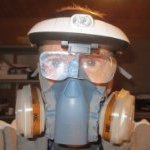
Soldier of the Armed Forces of Ukraine (16104) 1:16 ICM via H G Hannants Ltd We all know the story by now of the unprovoked invasion of Ukraine and the war that has raged for just over a year at time of writing. We won’t go further with the discussion of that, but suffice to say, it has resulted in the mobilisation of a lot of brave Ukrainians to defend their country from this incursion, and those efforts are ongoing during the bitter cold of the winter that is more than a bit colder than those we have here in the UK. Stay safe, all of you! This figure as part of ICM’s range of 1:16 larger figures represents a soldier engaged in that conflict, however his stance is that of a man that is away from the front at least temporarily, posing for the sculptor in a relaxed manner, whilst still carrying his war-fighting kit about his person. The kit arrives in a shallow top-opening box, with the usual captive flap on the lower tray. Inside are two sprues of grey styrene, two in black, an instruction sheet and a glossy colour copy of the box art if you would like to display it in your modelling room or somewhere in your home as a symbol of support. The instructions consist of a sprue diagram, a paint conversion chart with ICM, Revell and Tamiya codes alongside the colour names and swatches, then on the reverse is a detailed trio of drawings of the soldier from three angles, complete with part numbers and paint suggestions for the part. A swatch of digital camouflage that is commonly used by Ukrainian troops is also given, although a chicken like me would be looking for some camouflage decals in 1:16, as I have done already for my 1:35 Ukrainian figures. The majority of the parts for the figure are on the larger sprue, including the packs and pouches that a modern soldier carries on his or her tactical vest with its MOLLE loops making everything modular. The figure is broken down in a similar manner to a 1:35 example, although the torso is split into front and rear halves to prevent sink marks ruining the crisply moulded detail, especially the patch on his chest that appears to be of a raccoon. The soldier is wearing a covered modern helmet that is moulded in two halves, and has a pair of goggles in a protective bag strapped to the front, with most of the strap moulded into the helmet halves. The chin-strap is separate and formed from three fine parts that gives you the option to depict it closed or open for a more candid look. The fingers of both the soldier’s hands are also separate, as his hands are draped over and around his AK-74 variant, which has a 40mm Underslung Grenade Launcher (UGL) beneath the weapon’s barrel. He is also carrying a slide-out portable missile launcher across his back, while his AK is fed by the ammunition within the pouches around his waist, which are joined by other pouches and bags, with two types of comms on his chest, and various other small accessories, including a handset for his radio, grenades, bayonet, knife, magazines for his AK, medical shears, and buckles. There is also a choice of an AK without a UGL, and next door on the sprue are the plastic portion of the knee-pads that fit over the moulded-in cushions and straps, plus separate boot soles with finely engraved tread patterns evident. The base is moulded in black styrene, and has a choice of four different surfaces for the top and a flat base for the bottom. The choices comprise a flat asphalt surface plus three styles of cobble or paving stones. Conclusion In line with the stylised flag on the box lid, a brave Ukrainian soldier sculpted in great detail in a natural pose and with realistic cloth drape, that coupled with sympathetic painting should give an impressive result. Highly recommended. Available in the UK from importers H G Hannants Ltd. Review sample courtesy of
-
OV-10A Bronco US Marines (48305) 1:48 ICM via H G Hannants Ltd The Bronco was conceived as a light attack, long loiter aircraft of modest size, enabling it to operate from roads close to the combat zone. As so often seems the case, the final design turned out to be much larger and heavier due to the requirements of the avionics and ejection seats, thus limiting its use to conventional airfields. The twin boom aircraft first flew in 1965 and was destined to serve with the US Navy, Air Force and Marines as a replacement for the Cessna O-1 Bird Dog & O-2 Skymaster. The Marines were the first to take the OV-10 into service as a forward air controller platform operating both night and day missions. Whilst the Bronco is best known for its operations in Vietnam, it also served in later conflicts as late as the Gulf War before being retired from US service in 1995. The USAF received Broncos in 1968 and deployed the aircraft in the Forward Air Control (FAC) role, using smoke laying methods initially, and later using laser targeting designators. Eventually it carried its own ground attack armament including rockets, machine guns and bombs that gave it the capability of Light Attack Aircraft, and made it a daunting prospect for the enemy to see overhead. The US Navy used it in this capacity in Vietnam, although attrition was quite severe, and later in its service several airframes were used as testbeds for special operations, eventually being transferred to the Marines. Seven export contracts were signed with other foreign operators including Germany, Columbia and Indonesia, the very last of which will be leaving service in the near future after long service. The Kit A reboxing of a new tooling from ICM with new decals and some other minor differences, which arrives in one of their standard top opening boxes with the captive inner lid, and has eleven sprues in grey styrene, one in clear, two sheets of decals and a glossy instruction booklet with spot colour inside and glossy colour profiles on the back pages. Unpacking the sprues reveals the detail is excellent, and the booms have raised as well as engraved rivets on their surface, which is just as it should be if you check out any walk arounds that get close enough to the aircraft to see them. The clear parts have been engineered so that they fit together as individual facets, and are crystal clear, allowing the modeller to see their hard work in the cockpit, providing they don’t put any gluey fingerprints on the glazing during the build. Overall, it looks like it will build into an excellent replica of the aircraft. Construction begins predictably with the cockpit, starting with the crew seats, of which there are two. The base of the seats are made from the curved lower and cushion, while the backs are formed from a shell with two cushions, one for the pilot’s back, the other for the headbox. The two elements are brought together and a small part is added to the headbox, then different rear detail and a launch rail are added to the rear of them both. There are colour call-outs as we go along, and two warning decals are supplied for the seats, although these are shown applied to the cushions, which seems odd, but having checked some references, that’s where they go. Every day’s a school day! The rear seat is glued to the cockpit floor which has a bulkhead and a shelf moulded into the rear, then side consoles are fixed onto the floor around the seat with control column on a lateral support, and a throttle quadrant that sits on top of a raised portion of the port console. A divider between the two seats is prepared with rudder pedals and other details, then has a choice of either of two instrument panels added atop the flat section, based on your decal choice. These are well detailed and have dial decals for each option. The divider is glued in place, then the front cockpit is made up starting with the seat again, but with a different set of launch rail parts with “antennae” to the side of the headbox. He too gets a control column and floor-mounted rudder pedals, after which the seat is bracketed by side consoles that have detailed tops, but no decals which is a shame. A bulkhead for within the footwell of the front cockpit is created from several parts, and fixed in place with the details facing forward, forming the rear bulkhead of the nose gear bay. The pilot gets a well-appointed instrument panel with coaming and decal, plus a number of small parts sitting on top of the coaming. This is glued in, and more details are added to the rear shelf in the shape of equipment boxes that probably have festive twinkling lights on the real thing. The cockpit is put to the side briefly while the crew nacelle is prepared with interior sidewall details, plus an internal frame that runs up the side of the canopy. You are advised to align this with the canopy sides, which have a shallow groove running top to bottom, so it would be an idea to glue the parts, then tape the canopy sides in place and align the frame with the groove, taping it in place until the glue sets. With the sides complete and painted internally, the cockpit can be secured inside and locked in place by bringing the two halves together. Providing you have painted the front of the crew nacelle, the nose gear bay is already complete and just needs the main strut, a diagonal support that goes far back under the canopy, and a pair of bay doors. The underside of the cockpit floor is then covered over by a well-detailed underside panel that has recesses ready for the stubby weapons pylons, and has a small central strake added toward the rear. Here it will be key to align the nacelle skins before the glue sets to avoid having to make good later and risk losing any of that lovely detail. The weapons “wings” need four holes drilling in their underside if you are going to hang weapons from them, then they are closed around a small rectangular insert that the barrels later plug into, the wingtips are added, and each one has an insert applied to the leading edge that makes up the rest of the fairings for the weapons. These are glued into their recesses on the underside, and are fitted with shackles on the twin pylons on their undersides if you plan on using weapons. Another small nose gear door fits to the diagonal leg, and the four-part nose wheel with separate hub parts is first trapped between the yoke, which is then glued to the bottom of the nose strut along with the other half of the oleo scissor-link. I suspect this could be a weak point of the nose gear, so ensure you leave this to set up for a good while before attempting to put weight on it. The addition of the optional four gun barrels to the winglets and a couple of sensors completes the crew nacelle for now. The upper wing of the Bronco is a single full-width part that also has a section of the fuselage upper and the twin boom tops moulded-in, while the underside is in four sections. Before the two surfaces are joined, two spar sections are attached to the upper wing straddling the future location of the engine nacelles, and if you plan on adding wing pylons, there are a few holes to be drilled in the outer lower panel of the wings. All the flying surfaces are separate and the twin flap sections per side are made of three parts laminated together, while the ailerons are a single part each to which are added balances and trim actuators. When completed, the six flying surface sections are fitted to the cut-outs at the rear of the wing unit along with a pair of actuators for the ailerons, a pair of exhaust deflectors on top of the engine nacelles, and a large sensor blister at the centre-rear. The wing assembly is then mated to the crew gondola, and the canopy is begun. The blown windscreen that offers the pilot a good field of view has a sight fitted to the top centre before it is glued to the front of the cockpit, then has the clear canopy roof put in place, bridging the gap between the windscreen and cockpit rear. The two canopy sides are next, and these parts are each single pieces, which doesn’t give the modeller the opportunity to prop the front two sections in the open position without taking their life in their hands and cutting the parts with a razor saw or fine scriber and a lot of trepidation. No doubt an aftermarket company will step-in here. Building of the two nacelles begins with the gear bays, which starts with the making of the gear legs that have two main parts and a Y-shaped insert that traps the lower section in place but leaves it movable. Two more parts make up the suspension strut, which are also trapped in place by a V-shaped insert, and then glue is applied to the previously mobile joint, setting the correct angle for the leg permanently. It is glued to the stepped bay forward roof with several small parts, after which it is joined by the detailed sidewalls, rear bulkhead and another few parts to close over the rear of the roof and add more detail. The tail fins have fairings removed and smoothed off for one decal option, and are then joined around the bay assembly, capped off at the front by the intakes and propeller backing plate. Underneath, the triangular inserts for this variant with their many raised rivets are glued in carefully to avoid damaging that lovely detail. The two-part rudder is fixed to each tail, and an exhaust is made up from two halves, with baffles within. Align these carefully to minimise the join-line and check your references to get this right. A small intake is added to the side of the nacelle just forward of the exhaust. This process if carried out twice of course, in mirror-image so your Bronco doesn’t fly round in circles. The large horizontal elevator panel is made from top and bottom surfaces plus the elevator itself, and this is slotted into position between the nacelles as they are glued into place under the wings. You might need to grow another hand or two to make this happen, or get yourself one of those wonderful jigs like that of EBMA to help hold everything in place for this. Four optional shark-fin spoilers can be glued onto their corresponding slots in the top of each wing if you wish, or leave them in the box for a clean upper wing. The twin props have the three blades moulded as one, with a front and back boss, and take care to install the correct props on the nacelles, as the blades (and the turboprop engines) are handed, spinning in opposite directions to cancel out the effect of torque steer. A windscreen wiper and various sensor lumps are added around the fuselage, with more underneath, at which point you’ll notice that the main gear is without wheels. Each of these are made of a two-part wheel and two-part hub, with no weighting moulded-in, although that’s easily remedied by a quick sanding of a flat-spot on the bottom, just don’t overdo it so it looks like it needs more air. There are two wing pylons on long supports to add to the outer wing panels if you chose to drill the holes in the underside of the wings, then it’s just a case of choosing which munitions you want to hang from them. There is a diagram showing which weapons can be fitted to which pylons, but if you’re aiming for realism, check your references to establish real-world load-outs for training and live-fire missions. In the box you get the following: 2 x LAU-33 twin rocket pods 2 x LAU-069A 21 rocket pods 2 x Mk.77 Incendiary bombs 2 x LAU-68 6 rocket pods 2 x 150gal fuel tanks 2 x Mk.81 Lowdrag iron bombs with optional daisy-cutter fuse 2 x Mk.81 Snakeye iron bombs with optional daisy-cutter fuse 2 x Mk.82 Snakeye iron bombs with optional daisy-cutter fuse 2 x Mk.82 Lowdrag iron bombs with optional daisy-cutter fuse 2 x LAU-10A 4 rocket pods The detail of the individual weapons is excellent, with multiple parts for fins, fuses and rockets, and only the seamlines to clean up along the way. The canopy is about as clear as can be, so it’s going to be important to mask it up before you inadvertently ruin the startling clarity. Although masks aren’t included in the box, there is a handy template near the back of the instructions that you can place tape on and cut out masks for your use on the model. Each section is numbered and there is another drawing showing their location on the canopy. Very handy! Markings There are five options in the rear of the instructions in various schemes, including plain and camouflaged options. From the box you can build one of the following: 155434 US Marine Corps., 1987 155434 Marine Observation Sqn. 1 (VMO-1), Spring 1990 155454 Marine Observation Sqn. 2 (VMO-2), Summer 1990 155465 Marine Observation Sqn. 1 (VMO-1),Saudi Arabia, 1991 155434, US Marine Corps., 1991 Decals are printed by ICM’s usual partners, with good registration, sharpness, and colour density, with a thin gloss carrier film cut close to the printed areas. The weapons all have stencils to apply, which are shown next to each profile, as their colours varied over time. There are also rear and white tip decals for the props, and the large wide T-shapes on the upper wings are also included as decals, as are the tapered exhaust gas “hiders” on some of the decal options. Conclusion The Bronco is an appealing aircraft, and this new boxing with a wide choice of schemes is an excellent looking model that is crammed full of detail, and widens up the market further for the Bronco loving modeller to include the US Marines. Very highly recommended. Available in the UK from importers H G Hannants Ltd. Review sample courtesy of
-
WWI US Infantry Acrylic Paint Set (3024) ICM via H G Hannants Ltd ICM have recently released their own brand of acrylic paints on the market, and are creating some kit specific sets to go with their major releases, of which this is one. The set arrives in a cardboard box with six screw-capped bottles inside, each containing 12ml of paint. The bottles are clear Polypropylene, and are capped with cylindrical tops with knurled sides, and a one-time security seal that you break on first opening. A label on the side gives you basic information about the colour and code, a little information regarding application in English and Ukrainian and a bar-code. This set provides the major colours to assist you in painting the figures of the new WWI US Expeditionary Force boxed set from ICM themselves that you can find here, and you will find the following colours in the box: 1059 Green Ochre 1055 Deck Tan 1061 Green Brown 1050 Saddle Brown 1008 Deep Brown 2002 Satin Varnish The paint is thick in the bottle, with plenty of headroom between the surface of the paint and the lip of the neck. I dropped a glass stirring ball into each bottle, and they took a few seconds to disappear beneath the surface, indicating their viscosity. On the rear of the pack is an example of the usage of these colours using the kit mentioned above, by reproducing the drawings of the figures with arrows showing the appropriate colour swatches for each part. During testing, I used Ultimate Acrylic Thinners to dilute the paint to spray through my Gunze PS770 airbrush, which has a 0.18 needle chucked in. The paint dilutes well once it has been mixed thoroughly, and sprays well through my airbrush, which has a smaller than usual needle that is a good test of the finesse of the pigment grind of any brand, some of which don’t spray very well though anything less than a 0.3mm needle. There were no problems with blockages at all, and the coverage was excellent after my usual ad hoc dilution method, which was probably nowhere near the 40-60% thinners or water that’s suggested on the pack. Apart from the varnish, the other paints all dry to a matt finish. In past tests, the Satin Varnish worked very well diluted with water, sprayed over the spoons that were also partially taped up to perform two functions at once. The satin patina that resulted is exactly what was expected, and the tape lifted no paint at all, despite my best efforts to do so. Bear in mind that the spoons were prepped by a buff with a very fine sanding sponge to give them the best chance of adhesion. Using a brush, the colours cover well two coats with minimal brush marks visible. Conclusion The paints were excellent through the airbrush with nothing in the way of drama during the testing process, including the Oily Steel and Satin Varnish. There is a little less paint in the bottles than some brands, but a shade more than others, so it’s about average. That is more than offset by the very reasonable price they’re asking for the set, even at RRP. Highly recommended. Available in the UK from importers H G Hannants Ltd. Review sample courtesy of
-
 Fresh from battle with the Revell B-17f "Memphis Belle" I'm getting ready to build Revell's 1/48 JU 88 A4 Some time ago I bought Eagle Editions' decal sheet which includes F1+BR winter camouflaged marking set One lesson I learned from the B-17 is an hour spent on the exterior is worth at least five on the interior, so I intend to work through the interior in a quality, but quick way, no scratch building and no AM Then focus on the exterior Obviously the winter camo is going to be interesting I note the instructions say to paint RLM70/71 splinter pattern first, then go over roughly in white, then add decals The picture they reference seems to support this: In this build @Kilroy1988 initially applies the white distemper over the green camo, then applies the decals, albeit he overspays some white over the decals afterward @Spitfire31 comments that the white would have been applied around the markings, leaving exposed green camo around the markings The Eagle Cals decal set has a drawing of how they see the plane, and the markings look clean, and there are no obvious gaps around them where the guys were avoiding overpainting them. There are gaps around the cockpit windows, they were obviously told to give the glass a wide berth So, what's it to be? Oh hang on, since writing that I've seen this: https://akinteractive.forumotion.com/t1694-winter-white-wash-ju-88 Wow, what a stunner! So looking carefully at Jamie's model we can see he believes they did paint round the lettering, but very carefully I think I'm going to: paint the green camo 2 x Klear Apply the decals 2 x Klear Mask the lettering crosses Spray very thin layer of thinned white, but try to avoid the markings Attack it from the front to back with a toothbrush or 240 grit sandpaper or both 1 x Klear Weathering, exhaust etc Last Klear Any thoughts?
 -
Armed Forces of Ukraine Acrylic Paint Set (3025) ICM via H G Hannants Ltd ICM have recently released their own brand of acrylic paints on the market, and are creating some kit specific sets to go with their major releases, of which this is one. The set arrives in a cardboard box with six screw-capped bottles inside, each containing 12ml of paint. The bottles are clear Polypropylene, and are capped with cylindrical tops with knurled sides, and a one-time security seal that you break on first opening. A label on the side gives you basic information about the colour and code, a little information regarding application in English and Ukrainian and a bar-code. This set provides the major colours to assist you in painting your Stugna-P Complex Anti-Tank Missile Launcher with crew from ICM themselves that we reviewed here, and you will find the following colours in the box: 1072 US Dark Green 1035 Grey Green 1041 Buff 1069 Extra Dark Green 1054 Chocolate 2001 Matt Varnish The paint is thick in the bottle, with plenty of headroom between the surface of the paint and the lip of the neck. I dropped a glass stirring ball into each bottle, and they took a few seconds to disappear beneath the surface, indicating their viscosity. On the rear of the pack is an example of the usage of these colours using the kit mentioned above, and also depicts a sample of the digital camouflage that is often worn by the brave soldiers of the Ukraine. During testing, I used Ultimate Acrylic Thinners to dilute the paint to spray through my Gunze PS770 airbrush, which has a 0.18 needle chucked in. The paint dilutes well once it has been mixed thoroughly, and sprays well through my airbrush, which has a smaller than usual needle that is a good test of the finesse of the pigment grind of any brand, some of which don’t spray very well though anything less than a 0.3mm needle. There were no problems with blockages at all, and the coverage was excellent after my usual ad hoc dilution method, which was probably nowhere near the 40-60% thinners or water that’s suggested on the pack. Apart from the varnish, the other paints all dry to a matt finish. In past tests, the matt varnish worked very well diluted with water, sprayed over the spoons that were also partially taped up to perform two functions at once. The matt patina that resulted is exactly what was expected, and the tape lifted no paint at all, despite my best efforts to do so. Bear in mind that the spoons were prepped by a buff with a very fine sanding sponge to give them the best chance of adhesion. Using a brush, the colours cover well two coats with minimal brush marks visible. Conclusion The paints were excellent through the airbrush with nothing in the way of drama during the testing process, including the Oily Steel and Satin Varnish. The solid colours also brushed out very well, as did the varnish, but what happened to the Oily Steel is a mystery to me at this stage, possibly a bad mix, or some other oddity peculiar to my bottle or batch. There is a little less paint in the bottles than some brands, but a shade more than others, so it’s about average. That is more than offset by the very reasonable price they’re asking for the set, even at RRP. Highly recommended. Available in the UK from importers H G Hannants Ltd. Currently on back-order, however. Review sample courtesy of
-
AH-1G "Arctic Cobra" (48299) 1:48 ICM via H G Hannants Ltd Most modellers will instantly recognise the Bell AH-1 Cobra Attack Helicopter. The AH-1 was the first production Gunship or Attack Helicopter to see service. During the Vietnam war the US Army began to see the need for armed helicopter to escort its unarmed UH-1 Hueys into combat. In parallel to this Bell Helicopters had been investigating helicopter gunships as early as the late 1950s. In 1962 Bell displayed a mock up concept to the US Army. This Helicopter featured a 20mm gun pod, and a ball turret mounted grenade launcher. It was felt by the Army to be lightweight, under powered and not suitable. Following this the US Army launched and Advanced Aerial Fire Support System (AAFSS) competition. This competition gave rise to the Lockheed AH-56 Cheyenne heavy attack helicopter. However this proved to be to advanced for its time and was eventually cancelled in 1972 after 10 years of development (some things don't change!). Despite the AAFSS programme Bell stuck with its idea of a smaller, lighter gunship and invested its own money developing the AH-1. They used all of the proven components they could from the UH-1 platform, adding these to a newly designed fuselage. When The US Army therefore asked for plans for an interim gunship for Vietnam Bell was in a fortunate position to be able to offer the AH-1, or the Bell 209 as it was then called. Given the work Bell had already done the programme was completed in a relatively speed eight months and won the evaluation against the competition. In 1966 the US Army signed an initial contract for 110 aircraft. Some slight modifications were made to the production airframes. The heavy armoured glass canopy was replaced by Plexiglas with an improvement in performance. Wider rotor blades were fitted and the original retracting skids were replaced by simple fixed units. The G model was the initial 1966 production model gunship for the US Army, with one 1,400shp (1,000 kW) Avco Lycoming T53-13 turboshaft. Bell built over 1100 AH-1Gs between 1967 and 1973, and the Cobras would go on to fly over a million operational hours in Vietnam, approximately 300 were lost to combat and accidents during the war. The U.S. Marine Corps would use AH-1G Cobra in Vietnam for a short period before acquiring twin-engined AH-1J Cobras. The AH-1 went on to serve the US Army until it was replaced by the AH-64 Apache. The last one leaving active service in 1999. The AH-1G could be fitted with the The M-35 Gun System, this was a single M195 20mm cannon (a short-barrelled version of the six-barrel M61A1 Vulcan) on the port inboard pylon of the AH-1G. 950 rounds of ammunition were stored in boxes faired to the side of the aircraft. The system was primarily pilot controlled, but featured dual controls to be either pilot or gunner controlled. For this purpose the pilot was provided with a M73 sight. Some Cobras were tested by the US Army in low temperature conditions in Alaska. These were painted white with Arctic Red markings, these were known as Arctic Cobras. The Kit This is a recent tool from ICM & Special Hobby and brings us a long-overdue update to some of the older kits of the type on the market. This edition depicts airframes used in Alaska,. Inside the bag are eleven sprues in various sizes in grey styrene, a large clear sprue with a choice of canopies for upcoming versions, a decal sheet and their usual glossy A4 instruction booklet with spot colour throughout, and colour profiles of the decal options in the rear. Detail is excellent, as we’ve come to expect from ICM, especially in the cockpit, the exterior surface and the rotors, and the instruction booklet takes you through the build process with colour and scrap diagrams used to clarify the process. Construction begins with the cockpit, which will be highly visible through the crystal-clear canopy parts, and this starts with the twin tub (no, not a 60s washing machine), into which the quilted rear bulkhead, twin pilot controls and tail rotor pedals are fitted, followed closely by a pair of instrument panels with decals and deep coamings to reduce glare coming though the big canopy panes. The panels are different for front and rear crew, but their seats are very similar with armoured wings and sides on the cushioned seat, made of four parts each. Remarkably quickly we’re starting prep of the fuselage halves by drilling out a number of holes, adding the nose cone and tail fin, taking care to align them carefully as well as choosing the right one, as there are two tails on the sprues. The rotor-head is installed on a flat plate, allowing the head to rotate if you’re careful with the glue, then it is inserted into the fuselage along with the cockpit tub and the short exhaust trunk, closing it up and leaving it to set up so you can deal with the seams, and fill a small hole near the rotor head. With that done, the cockpit is outfitted with more armour panels on the internal sidewalls and on the port side exterior, adding a number of appliqué panels in two parts. The underside of the fuselage is bereft of detail until you add the two armoured panels under the cockpit, and glue an insert into the hole in the underside after drilling out a pair of holes from within for one variant. Two main intakes above that slot into recesses on the fuselage sides. The Cobra has wings! Little ones that are essentially weapons carriers, and these both have a separate wingtip and root mounted ammo pod under each one, the port pod later feeding the M35 gatling gun and a link between the starboard and port pods. At the rear you have a choice of two styles of tail stabilisers, one covered in rivets, the other nice and smooth. Speaking of the tail, the boom is covered in nicely rendered raised rivets, as is correct for the type. Two pylons attach to the underside of the winglets, one in the tip, another fitting into two holes. The short circular exhaust ring is installed at the open end of the trunking, with two small strengthening plates just underneath them. With the fuselage flipped on its back, the nose turret is next, with a pair of inserts added into the main turret part, and a 7.62mm gatling gun in one aperture, plus a 40mm grenade launcher in the other that you’ll need to drill out the muzzles on if you feel the urge. The very tip of the nose cone is separate, and has a pitot probe added near the top, then it’s time to add a few antennae and clear lights, plus the BIG gun, which has a separate hollow muzzle part, ammo feed and two other small parts, which is suspended from the underside of the port winglet, and linked to the ammo pod as mentioned earlier. The skids with the thicker supports and a whip-like safety skid under the tail finish off the main fuselage for now, after which the rotating parts are made. The Cobra had a twin-blade tail rotor that slots straight into a hole in the top of the tail fin, with an M-shaped control mechanism fixed to the centre, and a couple of clear parts added to fairings nearby. The main rotor sits on a chunky axle, over which a faceted washer slides, that is joined to the base by a pair of actuators. The two main blades are moulded as a single item, and are first detailed with additional parts before they are glued to the top of the drive-shaft, and supported by a pair of long control rods linked to the blades to adjust their incidence. A scrap diagram shows the various parts in grey to help you get everything correctly aligned. It is lowered into the top fairing later and glued into place, but first the canopy is completed. The Cobra’s canopy opens on different sides for each crew member, and has the long narrow top is fixed first, with the windscreen moulded-in. A small instrument is glued to the side of the screen, 3.5mm up from the bottom, after which it is glued onto the fuselage. The pilots exit from opposite sides, so after the sloped starboard section and port rear section are fixed in place, the two openers can be mounted in the open position and supported by props to achieve the correct angle for them. In addition to guns the Cobra could carry rocket pods, and two each of the seven-shot M157, M158 and four of the 19-shot M200 pods are included on separate sprues, the M157 & M200 pods cylindrical and with detail inserts in both ends. The bare tubed M158 pods have two ends, a central section and a curved cover at the top that is attached to the pylon. The final assembly is the optional towing equipment pack. This consists of a pair of graft-on wheels that attach to a pair of pegs on the upper rear of the skids, lifting them off the ground, and a pair of towing bars that also have castors near the skid-end to facilitate movement when they’re off the airframe. The bars attach to the front of the skids, then it’s down to you to find a suitable towing vehicle if you wish. Markings The decal sheet is in house from ICM, the decals look thin, in register and have minimal carrier film. 3 Options are included; 69-16440, Elmendorf AFB, Alaska 1975 67-15767, 120th Aviation Co. "Artic Knights", Fort Richardson, Alaska 1973 66-15250, Fort Richardson, Alaska 1968 Decals are printed by ICM’s usual partners, with good registration, sharpness and colour density, with a thin gloss carrier film cut close to the printed areas. Conclusion Another great Very highly recommended. Available in the UK from importers H G Hannants Ltd. Review sample courtesy of
-
The Crew of Stugna-P Anti-Tank Complex (35750) 1:35 ICM via H G Hannants Ltd In Ukrainian, the Стугна-П or Stugna-P, or sometimes Stuhna-P, depending on the translation, is a highly adaptable anti-tank weapon that was originally designed in Belorussia, but after 2014 was fitted with a new control unit of Ukrainian design. It is a capable platform that can attack targets from extremely close to medium range, attacking various types of target that can either be stationary or mobile. Sometimes called Skif, it can penetrate standard or composite armour and Explosive Reactive Armour, and is also able to penetrate bunkers and other soft targets, including helicopters. If there is no incoming fire or other impetus to vacate the area, the missile can be set up by its minimum crew of three and manually guided to target by its operator, but if stealth or absence is good for continued good health, it can be launched in fire-and-forget mode, with no external input required after initial targeting and launch. The weapon is mounted on a tripod in a tubular launcher, and the guidance computer is akin to a ruggedised laptop with a screen and game controller-style joystick. It can be operated remotely by a 50m cable in case there is a chance of the launch plume being spotted by the enemy, firing a HEAT (High Explosive Anti-Tank) round with dual warheads that can penetrate thick armour after detonating appliqué armour with the first charge. It was originally designed with the M1 Abrams in mind during the Cold War, but with a High Explosive fragmentation missile it can be used to create havoc with entrenched troop positions. The Kit This new set combines a Skif unit with a four-man crew, and arrives in a small top-opening box with the usual captive lid attached to the bottom tray. Inside are two sprues, one containing the weapon, the other the parts for the crew. The instruction sheet is printed on glossy paper on both sides of a folded sheet of A3, one side containing a sprue diagram and colour chart, the second page the build steps for the weapon, and the remaining two pages covered with detailed drawings of the figures. Construction of the Stugna-P is a relatively short process, consisting of creating the tripod from three legs, one with the pedestal moulded-in, then making up the missile tube from two halves, building a box that the launch tube sits on from three parts with top and bottom pivots, making up the sighting assembly from six parts, including the lens in a tubular housing, then putting the elements together and joining the two halves of the control “box”, which has additional detailed painting instructions. The weapon is painted either camouflage green or desert sand, then the instructions turn to the figures. The crew are each broken down into torso, arms, legs and head that are moulded separately, plus modern MICH-style helmets, pouches and bags, four AK derivative rifles and a pistol in a holster. The figures are crisply sculpted and are wearing modern combat gear, including MOLLE loop vests and pouches, covered helmets, combat boots and tactical gloves. There are also four sets of goggles to strap to the helmets or over the crew’s eyes if you’re no good at faces, or think they need protecting from debris kicked up by a missile launch. The figures are shown as drawings with arrows pointing out the part numbers and paint letter codes that correspond to the table on the front of the booklet in ICM, Revell and Tamiya systems. To assist with painting the figures’ uniforms, a swatch of digital camouflage that is worn by many of the Ukrainian soldiers is printed with the figure drawings, although I’ll be looking for some camouflage decals to ease the task when I get around to building this set. Conclusion The Ukrainian flag swatch and slogan on the front of the box is good to see, the figures and launcher are finely moulded, and should build up into an excellent model either for display on your shelves or within a diorama. Highly recommended. Available in the UK from importers H G Hannants Ltd. Review sample courtesy of
-
’The English Patient’ (32053) Movie Aircraft Tiger Moth & Stearman 1:32 ICM via H G Hannants Ltd The movie ‘The English Patient’ was the screen adaptation of a novel by Michael Ondaatje and was directed by Anthony Minghella with a quality cast, many of whom went on to become stars in their own right. It starred Ralph Fiennes as a hideously burned pilot near the end of WWII with Juliette Binoche playing a nurse caring for him until he succumbed to his injuries, after which she would catch up with her unit. Of course, nothing is straightforward, and various other characters appear, muddying the waters and adding intrigue to the piece. I’ve never watched it, so if I’m off beam anywhere you’ll just have to chalk it up to me disliking romance movies, even though they’re set in WWII. Two aircraft make an appearance in the movie, namely the Tiger Moth and the Stearman, which are the subject of this reboxing of two of ICM’s recent large-scale kits. Whether the Stearman would have been in British service at the time is a moot point, as it was used in the film and that’s all that matters. The Tiger Moth The de Havilland Tiger Moth was one of the most important and most widely produced trainer aircraft to have seen service with the RAF. It was designed by Geoffrey de Havilland himself in the 1930s and was based on the Gypsy Moth, suitably redesigned to meet Air Ministry Specification 13/31. In comparison to its predecessor, the Tiger Moth's wings were swept and repositioned, and the cockpits were redesigned to make escape easier. The airframe was also strengthened and the engine exhaust system was redesigned. The Tiger Moth entered service with the RAF in 1932 and remained in service until well after the war. Over 8,000 examples were completed and the type also served with the Royal Australian Air Force, the Royal Canadian Air Force and the Royal New Zealand Air Force as well as a great many other military and civilian operators. In service it proved itself to be ideally suited to its role; easy enough to fly, but challenging enough to weed out the weaker students. It was also cheap and easy to maintain. Further variants would be the DH.82C fitted with an enclosed hood for cold weather operations in Canada; and the Queen Bee which was an unmanned radio-controlled target drone that resulted in a thinning of the herd of surviving airframes. Always popular with civilian users, many Tiger Moths found their way into private ownership after the War, with many maintained in flying condition to this day. This is a reboxing of the recent tool from ICM that was first released in 2020, so it’s a thoroughly modern model. There are four sprues in grey styrene plus one of clear parts, and a shared decal sheet for both aircraft. The detail is excellent as we’ve come to expect from ICM, and providing you aren’t phobic about rigging, should make a straight-forward build. Construction begins with drilling holes in the two fuselage halves, using holes that are pre-thinned from the inside to ease the way. The fuselage halves are then detailed with throttle quadrants, instrument panels with dial decals, and the bulkheads between the two seating areas. At this time there are a couple more 0.3mm holes drilled in the top cowling in front of the cockpit to insert more rigging wires, which you’ll need to supply yourself, along with more threaded through the holes in the fuselage sides that you drilled earlier. Helpfully, the instructions tell you the length of wire that you should plan for, although I’d be tempted to use the numbers as a minimum value, just in case. You can always cut some off, but adding some on is much more of a skill. With that the fuselage is closed up, a firewall is inserted into the front, and an elevator inserted onto a rectangular peg in the rear of the fuselage, with the wider strakes that are fitted to the decal options, followed by the standard rudder fin, which has the tail skid moulded into the bottom. There is a good representation of the four-cylinder Gypsy Major engine that outputs less power than my perfectly normal family car, which makes one stop and think for a second. The block is in two halves that trap the conical drive-shaft inside, exhaust manifold, mounts and other ancillaries, with a baffle on one side, after which it can be glued into the firewall at the front of the fuselage, and have the cowling parts installed along with the open or closed access doors for the crew, small intake on the starboard cowling, and bumper-strips on the forward edge of each cockpit aperture. The lucky crew have a three-faceted windscreen placed in recesses in front of them to keep the bugs out of their teeth, then we move onto the wings. The wings are full-width parts, and the lower wing is made first, drilling rigging holes in the top surface, and leaving off the underside of this and the topside of the upper wing until after the rigging is complete. Whilst that might work for some, I’d be a little wary of gluing big parts such as the wings together after painting, although that’s just my opinion. You may have noticed there were no more cockpit details made up earlier, which is because the rest of the cockpit is built on the lower wing centre, as that’s where you will find the cockpit floor. A narrow control assembly is made first with rudder bars and control columns in duplicate, fitting into the cockpit floor on eight small rectangular slots, then joined by the aft seat, and the weird front seat that is moulded as a deep depression into the bulkhead between the two. The lower wing (upper only) is then mated with the fuselage, completing the cockpit at the same time. The interplane struts are individual parts in the outer wings, with two Z-shaped cabane struts fixed high on the fuselage sides just in front of the cockpit. More rigging holes are drilled into the lower half of the upper wing before joining it to the struts and adding the ribbed fuel tank to the centre of the upper wing. The next two diagrams show the location of the rigging using red lines, dotting them where they pass out of sight, and numbering them in a dot-to-dot fashion. After completion of rigging, the upper-upper and lower-lower wing halves are glued in place, hiding any messy rigging knots that you might have left. It does make for a clean job of the rigging, but I’m no expert at rigging. The upper wing has a pair of slats added to the leading edge, and ailerons to the lower trailing edge, then it’s time to make the landing gear. The wheels of the Tiger Moth are moulded in two halves, and slide over the axle-ends of a single complex W-shaped (ish) strut, which once it is in place is buttressed by four support struts that prevent the gear collapsing on landing. A little L-shaped tube glues to the underside of the fuselage while it’s upside down, and actuators are added under the ailerons, plus a couple of support struts are fitted between the elevators and fuselage, which also have triangular actuators added to small slots that are mirrored on the rudder, with more rigging added there later on. The prop is a single part that snugs into the tapered drive-shaft, and after completion of the final rigging to the tail, a further diagram has a set of shapes printed that you can use to pattern your own masks for the two canopies if you don’t want to spend extra money on a masking set. I like these, but haven’t used them yet, and would suggest reducing the tape’s stickiness by applying it to a clean surface first, to avoid tearing or marring the paper when you remove it. The Stearman The Stearman Aircraft Corporation was founded in 1927 by Lloyd Stearman. then in 1929 it was sold to The United Transport & Aircraft Corporation. This would then split in 1934 due to US Antitrust legislation with Boing which had been a part of it becoming its own business again; Stearman then became a subsidiary of Boeing. At about this time they designed what would become their most famous aircraft the Model 75 Kaydet. The new aircraft was a conventional tail wheeled biplane with an exposed radial engine. The aircraft was selected as the basic primary trainer for the USAAF and the USN, as well as for the Royal Canadian Air Force. In USAAF Service it would be designated the PT-13 with a Lycoming R-680 engine, The PT-17 with a Continental R-670-5 engine, and a PT-18 with a Jacobs R-755 engine. The USN had the NS, and NS2 with a variety of engines. Canadian PT-27 aircraft were USAAF PT-17s supplied under Lease Lend. In total over 10,000 airframes were built, many were sold off post war, and a lot of these still survive today. This is a reboxing of the recent Stearman PT-17 Kaydet kit, and consists of four sprues in grey styrene and another small sprue of clear parts, plus the afore mentioned shared decal sheet, and a shared instruction booklet. Construction begins with the cockpit, which is mostly empty space with a tubular framework holding all the instruments and controls. The sidewall frames are detailed, as is the floor with a pair of linked control columns, then they are joined together and held perpendicular to each other by a triangular cross-brace. The two seats are each a single part with a ladder frame added at the rear, and they slip in between the sides, strengthening the assembly further, then the fuselage is prepared for closure and the insertion of the cockpit assembly. Just a fire extinguisher is (ironically) added to the port sidewall, which has ribbed detail moulded-in, then the two halves are closed up around the tail-wheel, which has a separate wheel part slipped over the axle. An insert with riveted panelling is placed under the fuselage between the wheel struts, which are incidentally moulded into the two fuselage halves, then the cockpit assembly can be pushed in from the front and secured on pins, allowing the ribbing to be seen through the framework. The upper fuselage deck is separate and has the two instrument panels and back rests glued to the underside before it is fixed in place over the cockpit, closing up the fuselage. Another shorter insert fits under the front of the fuselage with another added to the port side, with the firewall closing up the front. The landing gear strut ends are simple affairs with separate scissor-links that slot into the legs after adding the two-part wheels, and are covered over by inner panels that are added to the moulded-in legs. Your model can now stand on its own three wheels for the first time. The flying surfaces are started by joining the two halves of the elevator fins together, and fixing the flying surfaces to the rear, with the ability to pose them deflected if you wish. They fit into slots in the sides of the tail fin, which then receive a single thickness rudder with separate actuator. Both main wings are supplied as full span assemblies, with separate tops and ailerons on the lower wing only. A pair of clear wingtip lights are inserted into the upper wings, then the four cabane struts and two Z-shaped interplane struts are glued in place and the wing is then lowered onto the model, taking care to keep everything correctly aligned. The Continental R-670-5 7-cylinder radial engine of the Stearman is barely any more powerful than the Tiger Moth, and its six exhaust stacks are assembled on the firewall at the front of the fuselage, followed by the intake trunking and push-rods, then adding the carburettor underneath. The cylinder bank is made up from two halves, adding a short prop shaft from inside the front half that is covered over by a circular part to prevent it from falling out of position. The rear portion is glued into place, and a vertical housing is inserted between the bottom two cylinders, after which it can be fixed to the fuselage with a choice of two props, each with two blades. The narrower prop is a ground adjustable steel McCauley unit, while the thicker one is wooden fixed-pitch Sensenich unit. The last page of the instructions detail rigging of the model, spanning three steps that show the wires marked in red over a line-drawn diagram. To the side is a drawing that shows the shape of masks that you can make yourself to help you keep the clear parts from getting marred by paint during the build. Markings There is one option per aircraft as you would expect, as follows: DH.82A Tiger Moth G-AFFC Stearman Model 75 G-AFEA The decals are printed by ICM’s usual partners, and consist of dials, registration codes, and a few other small decals, with good register, sharpness and dense blacks. Conclusion Another good value boxed set from ICM that should appeal to more than just film buffs, but anyone interested in interwar biplane trainers too. Highly recommended. Review sample courtesy of
- 1 reply
-
- 5
-

-

-
- ICM
- H G Hannants Ltd
- (and 1 more)
-
 Well, off we go. I've had a soft spot for the Sea Gladiator since my Dad told me the story of Faith, Hope and Charity, and the part taken by the aircraft in the defence of Malta. Some decades ago, I spent a memorable 10 days in Malta which included a visit to N5520 Faith resting in the bowels of Fort St Elmo. I'm afraid I must confess that I gave her a tender kiss on the cowling and shed a tear. Fortunately, there were no witnesses. The kit comes with decals for N5519, another of the Malta Sea Gladiators, but it didn't survive the war, being destroyed in an air raid on 4 February 1941. This was Hope, coincidentally the name of my favourite Aunt. Either N5519 or N5520 would be most satisfying to model due to these connections. I'd like to finish the aircraft in prewar silver dope. AIMS Models offers a decal set which includes markings for N5519 in this style, serving aboard the ill fated HMS Glorious as war clouds gathered in June 1939. I wonder if N5520 was similarly aboard HMS Glorious or another carrier? According to an article published on The Scarf & Goggles Social Club website (credible source?); " ... in March 1940 ... 18 Gloster Sea Gladiators, believed to have consecutive serial numbers N5518 – N5535, were unloaded on the Island (Malta) in packing cases, bound for the carrier HMS Glorious." As HMS Glorious was sunk on 8 June, these aircraft were assigned to other stations; HMS Eagle, Egypt and Malta. The crated airframes raise a question or two. According to Wikipedia; "Of the 98 aircraft built as, or converted to, Sea Gladiators, 54 were still in service by the outbreak of the Second World War." So none of the airframes in crates were fresh from the manufacturer. But were they sourced from storage? Were they repaired or refurbished airframes? Had some/all already served aboard aircraft carriers? And is it Sea Gladiator Mk.II or simply Sea Gladiator? All help, advice and constructive crits most welcome. May all our builds be 'on the top line'.
- 46 replies
-
- 12
-
-
Yak-9K (32091) 1:32 ICM via HG Hannants Ltd The Yak-9 was an evolution of the successful Yak-7 fighter, and was intended to retake the initiative from the Nazis’ new Fw.190 and improved Bf.109s, which it successfully did. Production started in late 1942, and by summer 1943 there were enough in service to make a difference, playing a part in the crucial Kursk battle, thanks to its agility in the denser air at lower altitudes and the heavy armament it carried. It was made in a number of different variants with diverse intended uses, with the D fitted with additional fuel tanks for longer range, and the DD for longer range still. The Yak-9T was armed with a larger 37 mm Nudelman-Suranov NS-37 cannon firing through the spinner but with only 30 rounds of armour-piercing ammunition carried, which it could fire in two or three round bursts and was intended for use against maritime targets and light armour, where it was quite effective. Careful aim was key of course due to the shortage of ammunition, but when used against another aircraft, a solitary shell strike would rip an opponent to pieces, making the enemy’s day end very badly. Because of the additional weight of the massive gun and its ammo, the cockpit had to be moved aft slightly to counter the change in centre-of-gravity, and various issues reared their heads thanks to the substantial vibrations from firing the cannon. Its standard armament of a 20mm UBS cannon still carried a full complement of 220 rounds as an auxiliary to the main armament. Almost 3,000 were made, and the designers later went one further and installed a 45mm cannon in the Yak-9K that had to be fitted with a muzzle brake to counter recoil of crippling proportions that could cause loss of flight control if fired at slower speeds, as well as instigating leaks of all manner of fluids due to the severe vibrations set up during firing. The pilot also wasn’t immune from the recoil, being tossed around the cockpit on firing, although a good aim was possible at high speed, and the impact of two or three 45mm rounds would literally disintegrate any aircraft that got in the way in a dramatic manner. Post war saw the continued development of the type, which involved the installation of a more powerful engine, and these were later hived off to Soviet-friendly satellite states at the end of the 40s, where they served into the 50s, although their unusual manual lubrication system saw accidents caused by engines seizing due to pilots that were engrossed in flying and fighting their aircraft forgetting to operate the hand-cranked lubrication lever in the cockpit. The Kit This is a minor additive reboxing of a brand-new tooling of this capable Soviet fighter from our friends at ICM, and it arrives in one of their standard top-opening boxes with the usual captive inner lid, and an attractive painting of the subject matter on the top. Inside the box are six sprues in grey styrene, a clear sprue in its own bag, a rectangular decal sheet and the instructions with colour covers and spot colour throughout, plus colour profiles for the decal options on the rear. Detail is crisp throughout the model, but don’t expect too many rivets to be visible on the exterior, as the metal structure was hidden away inside an outer layer of plywood impregnated with phenolic resin, that is better known in the west by its brand-name Bakelite. Construction begins with the port fuselage, which is adorned with the tubular cockpit framework and has six exhaust stubs on a runner pushed through the slot in the cowling from inside. The tips aren’t hollow, so prepare your pin vice if that bothers you at all. The starboard fuselage half goes through the same process, but adds the structure of the chin intake and its oil radiator cores, then the upper parts of the cockpit are made up, starting with the seat that has a pencil-rolled back cushion, and attaches to the short deck behind it, slotting into the starboard fuselage half along with a bulkhead and the instrument panel, which has a number of additional parts and a dial decal added along the way. With the completion of the tail-wheel assembly the fuselage can be closed up around these sub-assemblies, with an insert added under the chin, while most of the underside is open to the elements at this stage. The kit includes an engine that you can show off or hide away in its basic form of block with cylinder banks that is made out of nine parts plus another two for the cannon, which is similarly basic, but as none of it will be seen if you close the cowlings, that hardly matters. The muzzle brake can be found in the prop assembly if you’re in the mood to drill it out. The basic assembled engine slides into the front of the fuselage with the breech of the cannon slipping through a depression in the bulkhead, after which it can be covered over by two sections of cowling after removing a pair of pips that stand up from the seamline. If you intend to expose the engine however, the power plant is further detailed with an additional twenty parts for the engine itself, and another gaggle for the compartment around it, adding ancillaries, hoses, cowling support structure, the .50cal auxiliary cannon, and a pair of ammo cans for them both that slip into the aft section in front of the cockpit to create a nice replica with plenty of detail. The surround to the cockpit aperture is detailed with the gunsight mount and a piece of clear armoured glass behind the pilot, a small coaming, and the fixed rear canopy part, with the windscreen and its separate clear armoured panel, which is best “glued” on using a clear varnish such as Klear, taking care not to trap any bubbles in between the layers. The opening canopy slides back over the aft section, or you can leave it closed up to keep the snow out. In preparation for the wings, a short spar is created with a fluid tank in the centre and a couple of jacks at the ends, then a raised platform is made of the cockpit floor, which has the control column, rudder pedals and a flare pistol fixed in place for later attachment. The lower wing is full-width, and has the central radiator with textured front and rear panels added underneath, and the spar assembly inside, which forms the rear walls of the main gear bays that are joined by a number of other wall sections and internal ribs that are closed in by adding the upper wing halves. The bay roof is moulded into each wing half, with a little detail visible, but a single ejector-pin mark is visible, and is best dealt with before you glue the assembly together. The ailerons are individual parts that can be posed deflected, then the cockpit floor is glued in and a pair of tapering boxes are inserted in front, although I couldn’t divine their real-world purpose. The wings and fuselage are joined by carefully lowering the latter over the former, taking care not to bend or snap the control stick. The elevators and their fins are each two parts, and these also can be posed deflected if you wish, as can the rudder, which is also made of two parts and glued to the moulded-in fin. The landing gear is a little contrary in that it adds retraction jacks for the struts and inner bay doors first, which are also fitted at this time, with a scrap diagram showing the fine placement of the jack within the bay. The main wheels are each made from two halves with moulded-in hubs, and these are fixed to the axles at the bottom of the struts, with a separate scissor-link and captive bay door on each one, then they mate with the bays on a transverse pivot point, linking to the retraction jacks installed earlier. The model is finished off by adding the clear wingtip lights, gear-down indicator stalks on the wing tops, radio antenna on the fuselage spine, and the propeller assembly, which is made from the moulded-together blades plus front and rear spinner, then the brake of the new 45mm cannon’s barrel, which will need drilling out with a 1.4mm bit if you would like a hollow muzzle. Markings There are three markings options on the decal sheet, with three pages of profiles giving concise locations for the decals and letters showing the colours in reference to a table on the front page that gives names and codes in ICM, Revell and Tamiya brands of paint. From the box you can build one of the following: 274th Fighter Aviation Regiment, August 1944 43rd Fighter Aviation Regiment, 1944 812th Fighter Aviation Regiment, Germany 1945 Decals are by ICM’s usual partner, which is a guarantee of good registration, sharpness and colour density, with a thin gloss carrier film cut close to the printed areas. A decal for the instrument panel can be found in the top left of the sheet, with just the dials and white lines defining the sections of the panel, allowing the paint to show through from below. There are also a pair of fuel gauges for the wing tops that can be viewed by the pilot from his seat, rather than taking up space on the main panel. You might notice that the red stars have been cut in half by the decal designers, and the stars on the profiles are just a series of five < shaped points in white. Understandable under the circumstances. Add them yourself for historical correctness, or leave them off. Your choice, dear modeller. Conclusion A welcome new tooling of this impressive Soviet fighter that has the bigger 45mm, unreliable gun that should please many a large-scale modeller, with plenty of detail to be had from a relatively simple construction. Highly recommended. Available in the UK from importers H G Hannants Ltd. Review sample courtesy of
-
American Expeditionary Forces in Europe 1917-18 (DS3518) 1:35 ICM via H G Hannants Ltd The American forces were late to WWI due to isolationist concerns back home, but when they did finally arrive following the April 1917 declaration of war, their troops began flooding Europe, and although they were relatively inexperienced, they put the realistic fear of defeat into Germany and their allies, despite the problems America was having with initial mobilisation and logistics. Once in theatre, they used a combination of equipment imported from home and European kit where convenient, and their troops wore similar uniforms to the British and other allies, including the flat-brimmed battle-bowlers that lingered in British service until after WWII. By the time the Armistice was signed and enacted on the 11th November 1918, the American Army had morphed into a well-rounded, efficient fighting force through experience, some of it bitter. The Set This boxed set arrives in a standard-sized top-opening box, with the usual captive flap on the bottom tray. Inside are three truck kits, three identical driver figure sets, a set of marching infantry figures, and an accessory set containing a plethora of weapons and equipment for the figures and to dot around in the vehicles should you wish. The kits are as follows: Model T 1917 Ambulance (35661) Based upon the first real mass-produced chassis, the ambulance variant was outfitted with an overhanging box body at the rear, and a canvas roof that extended over the driving compartment, with space inside for patients either on litters or seated. By the end of the war, over 4,300 of these useful emergency vehicles were shipped to Europe for use by the Allies, although some enemy casualties were probably transported on occasion. The Kit Arriving on two sprues of grey styrene plus a clear sprue and small decal sheet, this kit is a full representation of the vehicle, and starts with the simple four-cylinder inline engine. The block is in two halves with a separate sump, cylinder head, pulleys, fan and hoses, with an integral transmission to the rear. The chassis is a single part that has the front wings moulded-in, between which the front axle and radiator are fixed so that the engine and two-part fuel tank can be inserted onto the flat area between the wings. The exhaust is joined to the left side of the engine, finishing under the support for the floor, then the rear axle with drive-shaft is laid over it, adding two diagonal struts between the axle and the transmission, and two more on the front axle plus the steering rack. The wheels are all single parts, and slot onto the ends of the front and rear axles to finish most work on the chassis. The body is built on the floor, adding the divider between the cab and rear compartment with a little window in the centre, plus the two sides with slatted benches down each side that should hold everything square. A pair of stretchers are made up on short supports with cross-braces, one of which is slipped into the floor bed before adding the lower rear section of the body. The top section has an entryway in the centre, then the rear bench seat is fixed into the outside front of the body before it is mated with the chassis and work on the cab can continue. The tapering floor has the foot pedals and handbrake inserted in the front, and a cushion that stretches across the width of the cab is glued to the floor so that it matches the rear cushion on the back wall. The firewall has a wide-framed windscreen moulded to the top of it, which can either be fitted with a trapezoid window, or can be removed entirely, depending on which variant you plan on building. A rack of fuel cans is made up to be fixed to the right side, and a steering column stub is attached to the left side of the engine, as this is an American vehicle, so once the cab floor is installed, the rest of the column, steering wheel and stalks can be slotted into the left side. Two side walls are supplied that fit in position against the space under the seat, and the engine is cowled over by a two-part set with a handle on the left side, leaving the possibility for an open engine bay if you wish. A set of running boards have a wooden box added to the front on each side, which mounts on the dropped side panel of the cab, then a C-shaped brace supports the windscreen against the body. The canvas roof that extends over the cab and body is a single part that has slat detail moulded onto the inside, and another stretcher is inserted into the body on the supports inside. The exterior is detailed by adding what looks a bit like a cooler box on the left, a rolled-up canvas door on the back of the body, a spare tyre and a locked box on the right running board, old skool lamps on the front of the cab, and two more modern circular units with clear lenses either side of the radiator at the front. A set of eyelets screw into the area next to the cowling. Another old-timey lamp is added to the rear corner next to a pair of stowed shovels on the left side, plus a hand-cranked horn on the side of the cab next to the driver. Markings There are four options on the small decal sheet, three of which are American, the last one is in French blue if you feel like breaking the theme. From the box you can build one of the following: Ambulance, USA, 1917 Ambulance, 524 SSU, AEF, France, 1918 Ambulance, 625 SSU AEF, France, 1918 Ambulance, 36 SS, French Army, France, 1918 The decals are by ICM’s usual partners, and are predominantly white, while the decals with multiple colours are in good registration, and all have good sharpness and colour density. FWD Type B WWI US Army Truck (35655) Built by the Four Wheel Drive (FWD) company, this was a very early truck used by the military of Britain and the US during WWI, beginning in 1915 with a small order from the British Army. It was full of unusual technology from a modern standpoint, but then vehicles of this type were still in their infancy, so that’s hardly surprising that there were a few dead-ends. It was originally supplied with solid tyres and the front wheels had a strange toed-in look due to the suspension geometry set up to give a light steering load. Its T-head engine produced a monstrous 36bhp for rice-pudding skin removal, and it could be connected to all four wheels or either front or rear in the event of necessity or damage to either drive-shaft. It also had a distinctive pig-nosed front because the engine was mounted below the cab, with only the radiator housed in the front and precious little (read: none) cover for the driver and crew. Over 12,000 were made up until the end of WWI, with them finding a ready market in the post-war period in the civilian sector, sometimes with pneumatic tyres added to improve the ride quality. The Kit This is a relatively new tooling from ICM, widening their WWI vehicle range again. There are four sprues in grey styrene plus a tiny clear sprue, a similarly small decal sheet and the instruction booklet with colour cover and spot-colour inside. It benefits from the same attention to detail that they have lavished on their other WWI kits and you get a full model that includes engine and chassis details not supplied in some other manufacturer’s kits. Construction begins with the double ladder chassis with suspension and cross-rails included and adding the axles, brakes and drive-shafts, most of which are broadly familiar but a little odd looking into the bargain. The larger rails of the chassis denote the rear of the vehicle, and at the front the steering linkage is added before the wheels are made up from three layers each plus hubcap, then fitted to each corner of the vehicle. The radiator core has its sides fitted then it is dropped into the front of the chassis, to be joined by the peculiar engine, which is very well detailed with almost 30 parts devoted to its construction. Once it is painted and in place the exhaust is threaded through the chassis and attached to the manifold outlets, with the diagram helpfully ghosting one of the wheels to improve your view. Power transfer boxes are suspended from the underside of the chassis rails with more drive-shafts, then up at the front the chassis is widened by adding tread-plated “shelves” to the sides before beginning work on the cab and snub-nosed bonnet. This assembly also includes an engine cover that ends up with the crew sitting on it and in the gap between the cowling and radiator the crew have a small footwell with driver controls and a fire extinguisher present, louvred side panels to the cowling and cooling fan for the radiator that is surrounded by a shaped cowling that plugs into the back of the radiator later. The fuel tank is made up from four sections plus two supports, then the lovely deeply upholstered crew sofa is put together with moulded-in buttons giving it a Victorian drawing room feel. The steering wheel and control levers are added to the sides of the cowling, then the seat is dropped on top with a nice cosy fuel tank right behind it for a frissant of danger. Exposed to the elements, high up and with extra heating in the summer, plus a big flammable tank right behind your seat. Awesome! The old-skool railway-style front lamps and U-mounted searchlight are put in place on the front and stowage is placed on the left foot-plate, presumably tied down so you don’t lose it on the corners, and the hand-crank starter can optionally be inserted into a socket on the front chassis rail if you wish. The 3-ton load bed begins with the floor and has five cross-beams slotted into position underneath, a front panel and two side panels that have braces added down the sides before they are installed, located on the pins on the end of each cross-beam. The tail gate is made up from frame and panel parts, then two stowage boxes are built up and fitted to the underside front of the bed, which is then mated with the chassis on several tabs and slots. You can model your truck with the tilt stowed or in place, with the former having five hoops fitted down the side panels to complete the assembly. For the covered bed there are five parts to make up the canvas tilt with some nice sag moulded-in. Hide the seams and paint it accordingly and you’ll end up with a believable looking tilt. Markings There are two decal options on the tiny sheet with just stencils on the sides to differentiate them from each other as they are both painted olive green. US Army, 1918 US Army, France, 1918 The few decals on the sheet are all white, so there’s no worries about registration, but colour density and sharpness are good. Standard B Liberty Truck (35650) The Liberty truck was a collaboration between the major US manufacturers and the Quartermasters Corps to reduce the need to carry spare parts for every weird and wacky truck that might find its way into service. The aim was to cut down on the breadth of inventory they needed to keep in stock to maintain the vehicles, and to reduce the training needed for their mechanics who only needed to be familiar with one main design. Production began in mid-1917 as America was becoming more involved in the Great War and with very few alterations over 9,000 were made before the end of hostilities. The vehicle's engine was also a collaboration and pushed out a staggering 52hp linked to a 4-speed box that drove all wheels, propelling the truck to a break-neck 15mph on a good road, drinking a gallon every seven miles at best, which with a 22-gallon tank gave it a short range. The Kit This isn't a brand-new tooling, but was released in 2018 so it's barely out of the "new" range. It is a high-quality kit with a lot of detail that provides a full interior, erected tilt and bare frame options, plus engine. There are four sprues in grey styrene, plus a clear sprue and decal sheet between the pages of the instruction booklet. Construction begins with the chassis with leaf suspension fore and aft, then spacer rails to join them together, radiator, axles and steering mechanism. The rear axle is a substantial chunk and has large drum brakes with a drive-shaft leading to a central transfer box in the middle of the chassis. Front mud guards, bumper bar with rebound springs are added, then it's time to fit the wheels with two singles at the front, and two pairs at the rear all with spoked hubs and moulded-in solid rubber tyres around the rim. There is a choice of hub caps on the front wheels, then the engine is made up from 11 parts and dropped in place on the chassis behind the radiator along with a two-part manifold and short exhaust pipe that you'll have to take a small drill to if you want the tip hollow. The connection to the radiator from the block sprouts from the top of the engine, and at this early stage the gear shifter is installed on the top of the box, ready for the crew cab later. The cab is formed on a stepped floor part that has tread-plate moulded in, to which the sides, full-width bench seat and the firewall with dashboard and fuel tank are attached. Two foldable crew steps are stowed under the floor, and the steering column inserts almost vertically into a hole in the floor, then the assembly is added behind the engine allowing the cowling to be fitted together with a perforated grille that sits forward of the cowling by a few scale inches. The hand brake attaches to the side of the transmission hump, and then it's time for the load bed. The floor is stiffened by five lateral ribs and the front wall is added and braced by the side panels, which also have 4 stiffeners, then two stowage boxes are glued in place under the floor at the front. The tailgate is made up from two layers and is added at whatever variation of open or closed you fancy, then the whole bed is fitted to the chassis on tabs and depressions to get the correct location. Back in the cab the steering wheel, searchlight with clear lens and horn are all fitted, the last two on the top of the dash, and two headlamps again with clear lenses are fixed to the outside front of the cab. The area is then decorated with a multitude of grab handles, closures and two towing hooks at the front of the chassis rail. A starter handle is inserted into the front, and the cab's tilt is made up from three styrene parts with two clear portholes and it too is fitted to the cab. The cover for the cargo bed can be modelled either hidden away with just the framework visible, or with the canvas draped over for a bit of variety. The framework option is quite delicate, so care will be needed when taking the frames off the sprues to avoid breakage. There are five of them and they fit at intervals to the sides with a substantial overlap for strength. The covered parts comprise front section, two sides with the exposed parts of the frames sticking down, a rolled-up rear cover, and separate roof section. All have realistic drape and creases moulded in, and your only task is to hide the seams before you apply paint, whilst avoiding breaking off the ends of the frames that hang down. Markings There are two decal options for the truck, both of which are the same colour, olive green for the body, and khaki for the canvas areas. The sheet is small and includes a few stencils, divisional badges and a warning to carry no more than 3 tons. US Army, 1918 US Army, France, 1918 US Drivers 1917-18 (35706) There are two figures on each of the three identical sprues, and the one doing the driving is a private with putties and utility belt with braces, while the co-driver is his commander with knee-high leather boots and Captain's rank insignia on his shoulder boards. They are both in the seated position as you'd expect and the driver has his hands out grasping the wheel with his feet appropriately angled for the pedals. This is ICM, so sculpting is excellent with simple parts breakdown along natural seams speeding up assembly and preparation for paint. Each figure is broken down into head, torso and separate arms and legs. The hats are separate parts to achieve a better brim and these have a flat contact patch with the equally flat-topped heads, plus moulded-in detail of the hat band with tassels. An excellent addition to your Liberty truck at a good price, or any other vehicle used by the US Army in WWI, although the driver may require a little adjustment if the controls for the driver are different. US Infantry 1917 (35689) This set arrives on a single sprue, and has parts for four WWI American soldiers, wearing a cavalry-style hat. They are all dressed in appropriate uniform for the era, and three of them are carrying their kit bags, apparently marching with their rifles slung over their shoulders. The other figure is taking a photograph with a period camera, which probably prompted the wave from one of the marching figures. The figures are sensibly broken down as torso, head, arms and legs, with the hats separate for fitting onto the flat tops of the heads. The extra parts on the sprue include the afore mentioned kit bags, pouches, and satchels. Some of the additional parts that are shown installed on the figures are from the accessories set below. WWI US Infantry Weapon and Equipment (35688) This set is spread over a single sprue that is stacked with additional equipment that can be used with the figures, vehicles and so forth. The set includes the following: Lewis Gun Chauchat CSRG Mle 1915 Machine Gun Browning M1918 BAR Machine Gun M1918 BAR Pouches (left) M1918 BAR Pouches (right) Springfield M1903 Rifle Springfield M1903 Rifle with Bayonet M1905 Bayonet M1905 Bayonet with Scabbard M1905 Bayonet Scabbard Springfield M1903 Rifle with Rifle Mortar Rifle Mortar Grenade Winchester M1897 Trench Gun with Bayonet M1897 Bayonet Scabbard Trench Knife Springfield Pouches x 3 Springfield Pouches x 2 Small Pouch Colt Army M1917 Revolver Smith & Wesson Army M1917 Revolver Army M1917 Revolver in Holster (left) Army M1917 Revolver in Holster (right) Revolver Ammo Pouch Colt M1911 Pistol Colt M1911 Pistol in Holster Colt M1911 Ammo Pouch M1 Grenade Shovel Shovel in Case Pickaxe Pickaxe in Case Axe Axe in Case Trench Periscope (Wood) Trench Periscope in Case Canteen Respirator in Bag Officer Bag Binocular Binocular Case M1917 Steel Helmet Compass Cover Some items are individuals, while others are supplied in multiples on the sprues, and yet more are built from a few parts, such as the magazine added to the top of the Lewis Gun, a choice of bipods, and separate bolts for the Springfield rifles. The instructions show line drawings of the items along with a numbered list as above, and on the opposite side of the page is a paint code table that corresponds to the letter codes in red. Conclusion This boxed set from ICM is about as densely packed as is possible in a relatively small box, containing three vehicle kits, four figure sets, and an accessory set to round out the package. Like most of their boxed sets, the instructions have been gathered together into a card binder, with all the decals stowed inside the front of the booklets. Excellent detail, realistic-looking figures, and a lot of modelling fun in a box. Highly recommended. Available in the UK from importers H G Hannants Ltd. Review sample courtesy of
-
Hi everyone, I'd like to introduce to you my latest release at Hypersonic Models. B-26K Coutner Invader wheels, in 1:48, for the ICM kit. The set is created in CAD to accurate dimensions and all components are delivered as 3D printed parts. Tyres and hubs are separate pieces, in order to facilitate the best printing result and make painting easier. Print supports are kept to a minimum, clean-up is roughly equal to a good resin cast item although each individual support is easier to clip away than a thick casting block. The detail includes very fine brake detail, valve stems, tyre sidewall detail (kept as small/faint as possible) and weighted/bulged tyres. The axle holes correspond to the ICM gear struts and also fix the off-centre issue of the kit hubs. Direct link: https://www.hypersonicmodels.com/product/b-26k-wheels I hope you'll like this set. Thanks for looking, Jeffrey
-
OV-10A Bronco US Attack Aircraft (48300) 1:48 ICM via Hannants The Bronco was conceived as a light attack, long loiter aircraft of modest size, enabling it to operate from roads close to the combat zone. As so often seems the case, the final design turned out to be much larger and heavier due to the requirements of the avionics and ejection seats, thus limiting its use to conventional airfields. The twin boom aircraft first flew in 1965 and was destined to serve with the US Navy, Airforce and Marines as a replacement for the Cessna O-1 Bird Dog & O-2 Skymaster. The Marines were the first to take the OV-10 into service as a forward air controller platform operating both night and day missions. Whilst the Bronco is best known for its operations in Vietnam, it also served in later conflicts as late as the Gulf War before being retired from US service in 1995. The USAF received Broncos in 1968 and deployed the aircraft in the Forward Air Control (FAC) role, using smoke laying methods initially, and later using laser targeting designators. Eventually it carried its own ground attack armament including rockets, machine guns and bombs that gave it the capability of Light Attack Aircraft, and made it a daunting prospect for the enemy to see overhead. Seven export contracts were signed with other foreign operators including Germany, Columbia and Indonesia, the very last of which will be leaving service in the near future after long service. The Kit This new tooling from ICM relieves us all of the ancient Testors kit with its legendarily incorrect wings and nacelle locations, which could only have been fixed with the help of a Paragon Designs set. This is a relief for this modeller, as there were also other blank areas that would have required some further work. Back to the matter in hand. A 100% new model from ICM, which arrives in one of their standard top opening boxes with the captive inner lid, and has ten sprues in grey styrene, one in clear, two sheets of decals and a glossy instruction booklet with spot colour inside and glossy colour profiles on the back pages. De-bagging the sprues reveals the detail is excellent, and the booms have raised as well as engraved rivets on their surface, which is just as it should be if you check out any walk arounds that get close enough to the aircraft to see them. The clear parts have been engineered so that they fit together as individual facets, and are crystal clear, allowing the modeller to see their hard work in the cockpit, providing they don’t put any gluey fingerprints on the glazing during the build. Overall, it looks like it will build into an excellent replica of the aircraft. Construction begins predictably with the cockpit, starting with the crew seats, of which there are two. The base of the seats are made from the curved lower and cushion, while the backs are formed from a shell with two cushions, one for the pilot’s back, the other for the headbox. The two elements are brought together and a small part is added to the headbox, then different rear detail and a launch rail are added to the rear of them both. There are colour call-outs as we go along, and two warning decals are supplied for the seats, although these are shown applied to the cushions, which seems odd, but having checked some references, that’s where they go. Every day’s a school day! The rear seat is glued to the cockpit floor which has a bulkhead and a shelf moulded into the rear, then side consoles are fixed onto the floor around the seat with control column on a lateral support, and a throttle quadrant that sits on top of a raised portion of the port console. A divider between the two seats is prepared with rudder pedals and other details, then has a choice of either of two instrument panels added atop the flat section, based on your decal choice. These are well detailed and have dial decals for each option. The divider is glued in place, then the front cockpit is made up starting with the seat again, but with a different set of launch rail parts with “antennae” to the side of the headbox. He too gets a control column and floor-mounted rudder pedals, after which the seat is bracketed by side consoles that have detailed tops, but no decals which is a shame. A bulkhead for within the footwell of the front cockpit is created from a number of parts, and fixed in place with the details facing forward, forming the rear bulkhead of the nose gear bay. The pilot gets a well-appointed instrument panel with coaming and decal, plus a number of small parts sitting on top of the coaming. This is glued in, and more details are added to the rear shelf in the shape of equipment boxes that probably have festive twinkling lights on the real thing, especially at Christmas. The cockpit is put to the side briefly while the crew nacelle is prepared with interior sidewall details, plus an internal frame that runs up the side of the canopy. You are advised to align this with the canopy sides, which have a shallow groove running top to bottom, so it would be an idea to glue the parts, then tape the canopy sides in place and align the frame with the groove, taping it in place until the glue sets. With the sides complete and painted internally, the cockpit can be secured inside and locked in place by bringing the two halves together. Providing you have painted the front of the crew nacelle, the nose gear bay is already complete and just needs the main strut, a diagonal support that goes far back under the canopy, and a pair of bay doors. The underside of the cockpit floor is then covered over by a well-detailed underside panel that has recesses ready for the stubby weapons pylons, and has a small central strake added toward the rear. Here it will be key to align the nacelle skins before the glue sets to avoid having to make good later and risk losing any of that lovely detail. The weapons “wings” need four holes drilling in their underside if you are going to hang weapons from them, then they are closed up around a small rectangular insert that the barrels later plug into, the wingtips are added, and each one has an insert applied to the leading edge that makes up the rest of the fairings for the weapons. These are glued into their recesses on the underside, and are fitted with shackles on the twin pylons on their undersides if you plan on using weapons. Another small nose gear door fits to the diagonal leg, and the four-part nose wheel with separate hub parts is first trapped between the yoke, which is then glued to the bottom of the nose strut along with the other half of the oleo scissor-link. I suspect this could be a weak point of the nose gear, so ensure you leave this to set up for a good while before attempting to put weight on it. The addition of the four gun barrels to the winglets and a couple of sensors completes the crew nacelle for now. The upper wing of the Bronco is a single full-width part that also has a section of the fuselage upper and the twin boom tops moulded-in, while the underside is in four sections. Before the two surfaces are joined, two spar sections are attached to the upper wing straddling the future location of the engine nacelles, and if you plan on adding wing pylons, there are a few holes to be drilled in the outer lower panel of the wings. All the flying surfaces are separate and the twin flap sections per side are made of three parts laminated together, while the ailerons are a single part each to which are added balances and trim actuators. When completed, the six flying surface sections are fitted to the cut-outs at the rear of the wing unit along with a pair of actuators for the ailerons, a pair of exhaust deflectors on top of the engine nacelles, and a large sensor blister at the centre-rear. The wing assembly is then mated to the crew gondola, and the canopy is begun. The blown windscreen that offers the pilot a good field of view has a sight fitted to the top centre before it is glued to the front of the cockpit, then has the clear canopy roof put in place, bridging the gap between the windscreen and cockpit rear. The two canopy sides are next, and these parts are each single pieces, which doesn’t give the modeller the opportunity to prop the front two sections in the open position without taking their life in their hands and cutting the parts with a razor saw or fine scriber and a lot of trepidation. No doubt an aftermarket company will step-in here. Building of the two nacelles begins with the gear bays, which starts with the making of the gear legs that have two main partss and a Y-shaped insert that traps the lower section in place but leaves it movable. Two more parts make up the suspension strut, which are also trapped in place by a V-shaped insert, and then glue is applied to the previously mobile joint, setting the correct angle for the leg permanently. It is glued to the stepped bay forward roof with a number of small parts, after which it is joined by the detailed sidewalls, rear bulkhead and another few parts to close over the rear of the roof and add more detail. The nacelle sides have a couple of holes drilled on each side, and these are joined around the bay assembly, capped off at the front by the intakes and propeller backing plate. Underneath, the triangular inserts with their many raised rivets are glued in carefully to avoid damaging that lovely detail, and two optional towel-rail antennae are glued into the holes on the sides of the nacelle. The two-part rudder is fixed to the tail, and an exhaust is made up from two halves, with baffles within. Align these carefully to minimise the join-line and check your references to get these right. A small intake is added to the side of the nacelle just forward of the exhaust. This process if carried out twice of course, in mirror-image so your Bronco doesn’t fly round in circles. The large horizontal elevator panel is made from top and bottom surfaces plus the elevator itself, and this is slotted into position between the nacelles as they are glued into place under the wings. You might need to grow another hand or two to make this happen, or get yourself one of those wonderful jigs like that of EBMA to help hold everything in place for this. Four optional shark-fin spoilers can be glued onto their corresponding slots in the top of each wing if you wish, or leave them in the box for a clean upper wing. The twin props have the three blades moulded as one, with a front and back boss, and take care to install the correct props on the nacelles, as the blades (and the turboprop engines) are handed, spinning in opposite directions to cancel out the effect of torque steer. A windscreen wiper and various sensor lumps are added around the fuselage, with more underneath, at which point you’ll notice that the main gear is without wheels. Each of these are made of a two-part wheel and two-part hub, with no weighting moulded-in, although that’s easily remedied by a quick sanding of a flat-spot on the bottom, just don’t overdo it so it looks like it needs more air. Fun with weapons is next, and this modeller thinks that the Bronco looks best when loaded for bear, as they say. There are two wing pylons on long supports to add to the outer wing panels, then it’s just a case of choosing which munitions you want to hang from them. There is a diagram showing which weapons can be fitted to which pylons, but if you’re aiming for realism, check your references to establish real-world load-outs for training and live-fire missions. In the box you get the following: 2 x LAU-33 twin rocket pods 2 x LAU-069A 21 rocket pods 2 x Mk.77 Incendiary bombs 2 x LAU-68 6 rocket pods 2 x 150gal fuel tanks 2 x Mk.81 Lowdrag iron bombs with optional daisy-cutter fuse 2 x Mk.81 Snakeye iron bombs with optional daisy-cutter fuse 2 x Mk.82 Snakeye iron bombs with optional daisy-cutter fuse 2 x Mk.82 Lowdrag iron bombs with optional daisy-cutter fuse 2 x LAU-10A 4 rocket pods The detail of the individual weapons is excellent, with multiple parts for fins, fuses and rockets, and only the seamlines to clean up along the way. The canopy is about as clear as can be, so it’s going to be important to mask it up before you inadvertently ruin the startling clarity. Although masks aren’t included in the box, there is a handy template near the back of the instructions that you can place tape on and cut out masks for your use on the model. Each section is numbered and there is another drawing showing their location on the canopy. Very handy! Markings There are five options in the rear of the instructions in various shades of grey and camouflage green, and there’s also a new paint set from ICM themselves that gives you all the shades you’ll need to paint the majority of the airframe as depicted in this boxing. You can read about that in a later review that we’ll link back once we’ve had chance to spray them out. From the box you can build one of the following: OV-10A 155471 Light Attack Sqn. 4 (VAL-4), ‘Black Ponies’, Binh Thuy, 1971 OV-10A 155456 Marine Observation Sqn. 6 (VMO-6), Quang Tri, 1969 OV-10A 67-14649, 20th Tactical Air Support Sqn., Da Nang, 1972 OV-10A 155416 Marine Observation Sqn. 2 (VMO-2), Da Nang, 1969 OV-10A 155416 Marine Observation Sqn. 2 (VMO-2), Da Nang, 1970 The 4th and 5th options depict the same airframe at different periods, which possibly had light grey wings earlier in its career, which was later painted green on the topside, and may have been painted a lighter or darker grey on the underside. The profiles give you the option and leave it up to you. Decals are printed by ICM’s usual partners, with good registration, sharpness and colour density, with a thin gloss carrier film cut close to the printed areas. The weapons all have stencils to apply, which are shown next to each profile, as their colours varied over time. There are also rear and white tip decals for the props, and the large wide T-shapes on the upper wings are also included as decals, as are the tapered exhaust gas “hiders” on some of the decal options. Conclusion I’m a happy bunny. I’ve always liked the Bronco, and this new tooling is an excellent looking model that is crammed full of detail that will doubtless encourage new decal sheets into the market to cater for the many buyers. The launch of the paint set is a clever move, encouraging modellers to try their new(ish) paint system. You know you want to! Very highly recommended. Available in the UK from importers H G Hannants Ltd. Review sample courtesy of
-
I-16 Type 10 with Chinese Pilots (32008) 1:32 ICM via H G Hannants Ltd The I-16 was a ground-breaking design that first flew in 1934, as it was both a monoplane, and benefited from having retractable landing gear. It was designed by the Polikarpov Design Bureau, and was also intended to have a totally enclosed cockpit, but Soviet pilots disliked being ensconced within their aircraft, perhaps harking back to the days of open-topped biplanes, and all this was despite the freezing temperatures that they had to endure, even at zero feet. It was a small aircraft that led to some diminutive nicknames such as Burro or Rata, depending on where it was in service. Early variants saw action in the Spanish Civil War as well as in Chinese hands against the Japanese invaders, and by the time WWII came around they were one of the major fighters in service with the Soviet Air Force in terms of numbers. Action against the Bf.109s of the Legion Condor during the Spanish conflict left the designers with the distinct impression that it was outclassed by larger, more modern designs, but production did not cease immediately thanks to the remaining development potential of the basic airframe. By the time the Type 10 came into production, it was fitted with four 12.7mm machine guns, two synchronised in the cowling, two more in the wings. It was also powered by a Wright Cyclone R-1820 engine, and had a sliding canopy, which many pilots still discarded by preference to improve their situational awareness or whatever their excuses were. Subsequent variants improved the armament further, installing 20mm cannons with the same designation (why??) for extra destructive power, and increasing the power and supplier of the engine, although the improvements there were incremental rather than revolutionary. By the middle of WWII the type was obsolete, and was retired in favour of more advanced and powerful designs. The Kit This is a reboxing of their recent kit that is based on the initial tooling that dates to 2017, but with the addition of a set of Chinese aircrew figures to sweeten the deal. It arrives in a medium-sized top-opening box that has a captive flap on the bottom tray, and inside are five sprues in grey styrene, a clear sprue, decal sheet, and instruction booklet. Detail is excellent, and you may notice immediately that there are a few extra large parts on the sprues that you will end up leaving there, as it’s cheaper and more efficient to do so, rather than retool existing sprues. The addition of the figures gives some potential for a diorama or vignette, or you could just stand them next to your finished model on a bare shelf. Unusually, construction begins with the wings, that are full-span underneath and has the gear bays moulded into the centre. It is closed over immediately with the upper surfaces, and a pair of formation lights are inserted into the tips, then the ailerons are made from two halves each and are fitted in place, deflected if you wish, inserting a perforated cowling into the gap in front of the gear bays at the same time. The cockpit is created in stages, starting with the rear bulkhead and seat, which is then suspended in the port fuselage half, which has ribbing moulded into the interior. A front frame and equipment are also added to the sidewall, and the floor is slipped through the two bulkheads from the front, locking in place on a couple of cut-outs in the correct locations. A couple of bottles are installed around the rear of the cockpit, some pilot controls that include rudder pedals and control column are fitted in the main area, followed by the clear instrument panel with decal and the pilot’s seat pan, plus a few more detail parts, with yet more on the starboard sidewall. At the same time, a firewall bulkhead has a saddle-tank applied to the front surface, and two gun troughs extending from the rear toward the pilot, ready for additional parts once the fuselage is closed up. In preparation for that, the rudder and elevator halves are joined, and the upper cowling over the gun troughs has a pair of clear lights inserted from within. Predictably, the rudder is trapped between the fuselage halves on closure, allowing it to pivot if you are careful with the glue. The deck in front of the cockpit is then inserted, and the cockpit door is also glued into place, after which dealing with the seams would be a good plan before you join the wings from beneath. The elevator flying surfaces form a single assembly when complete, and are trapped between the halves of the elevator fins, which attach to the rear of the fuselage on triangular tabs, closing them in with a short fairing later in the build. Your Rata is bereft of an engine at this stage, so a circular mount with zig-zag supports is built, followed by the rear of the motor with intake piping that slides into the centre along with an ancillaries box. The nine-cylinder radial engine is supplied as a front and rear half, with push-rods moulded into a separate shallow bell-housing. The back of the motor is peppered with nine exhaust tubes, each one a separate part, and individually shaped to exit the cowling at the rear through the various holes. A little test-fitting would be sensible before resorting to glue to ensure they all exit where they’re supposed to, after which you can join the mounts to the back of the engine and insert the whole assembly into the front of the fuselage, taking care not to knock off any exhausts as you do. The cowling is next, starting with the front, with the three-part intake with adjustable cooling made up first, leaving the centre section mobile in case the temperature drops on your workbench. The prop shaft is slipped through a hole in the centre, through a perforated spinner plate and two-blade prop, which is covered over by a stubby spinner cap. The prop is then glued to the lower cowling and a pair of guns are slotted into the gun troughs, then the remaining three parts of the cowling can be glued into position or left off at your whim. The windscreen is then glued into position over a clear gunsight, then it’s time to make the wheels. Each gear leg is made from a triangular combination strut that has a three-part captive door applied to the outside, plus a retraction strut that has its own door fixed to it near the top. Take care during this process, as some small areas should be removed with a sharp blade or file to make the main doors and struts accurate to the type. The wheels are two parts each and slide onto the axles perpendicular to the ground. The tail cone has a small light at the tip, and a skid keeps the back end from dragging on the ground. The final few parts include the wing-mounted guns, a pitot tube, and a strange ‘dongle’ hanging from the starboard cowling. WWII China Guomindang Air Force Pilots (32115) We’ve reviewed this three-figure set before, and it’s nice to see it again. The single sprue contains parts for three figures, one crew chief or officer, and two pilots, who are dressed in flight overalls, flying helmets and their parachute packs slung low to the rear. Each figure is highly detailed, and broken down with separate torso, legs, arms and heads, plus parachute packs for the pilots, and a satchel for the uniformed gentleman. He also has separate coat tails for realism, and a two-part cap with separate peak. Markings There are four decal options included on the sheet, each one having half a page of colour profiles devoted to the detail, with just a single wing depicting the underside to show the location of the national markings. From the box you can build one of the following: China Guomindang AF, 1939 23rd Chantay of China Guomindang AF, 1939 24th Chantay of China Guomindang AF, September 1940 24th Chantay of China Guomindang AF, Chengdu, June 1941 Decals are by ICM’s usual partners, which is a guarantee of good registration, sharpness and colour density, with a thin gloss carrier film cut close to the printed areas. Conclusion The I-16 is a small aircraft, even at this scale, and adding the three figures to the package gives it some human scale. Good detail and ICM’s usual fit and finish round out the package. Available in the UK from importers H G Hannants Ltd. Review sample courtesy of
-
Ki-21-Ia Sally (72205) 1:72 ICM via H G Hannants Ltd The Sally, as she was known by the Allies during WWII was a heavy bomber designed by Mitsubishi as a replacement for the Ki-20, in competition with Nakajima, who although they lost out on the design of the aircraft, were given the contract for the power plants, as their HA-5 engines were found to be superior to Mitsubishi’s offering originally installed. A small number of airframes were also built by Nakajima too, with a total of just over 2,000 built between them. It first flew in 1936 and was intended for long-range bombing missions against Soviet and Chinese opponents, first entering service in 1938 in operations against China. Initial experience showed that the design was lacking in some respects, extending to the crucial oxygen system that was found to be unreliable. The Ib was intended to address most of the issues, including the lack of armament and changes to the flying surfaces. It also had a remote tail gun installation, and could mount an additional fuel tank for extreme range missions. The type was pretty much obsolete by 1940, and mounting losses prompted the type’s withdrawal from front line service, and sale of some of the airframes to friendly nations. Uses were still found for the type with the Japanese forces however, and the remaining aircraft were used until the end of the war as cargo transports, trainers, troop transports and communications hacks. The later variants had improved engine performance with Mitsubishi units, some with alterations to the greenhouse behind the cockpit, which was changed to a turret on some, and removed entirely on transport variants. The Kit This is a reboxing with an additional sprue of a brand-new tool from ICM, who continue to produce new kits despite the difficult circumstances in their home country. The kit arrives in a shallow top-opening box that has a captive top flap on the bottom tray. Inside are six sprues in grey styrene, a clear sprue in a separate bag, decal sheet and the instruction booklet, which is printed in colour with colour profiles on the back pages. Detail is well up to modern standards, and extends to ribbing on the interior of the fuselage, full representation of the engines and a nice cockpit, plus a set of crystal clear glazing parts. Construction begins with the fuselage halves, which have the armed Ib tail added to the rear, a lozenge-shaped detail insert to make the wing root recess flush, and the side windows, plus an equipment insert in the cockpit area, and a line of trunking that extends from the trailing edge of the wing to the tail. The cockpit floor is a long part, with a recessed front end for the flight crew, detailed by adding the rudder pedals for the pilot, and the two seats, which both have separate seat cushions. The twin ‘bow tie’ control columns are inserted into the floor in front of the seats, and near the rear of the floor are two large tanks that attach on pins. The assembly is inserted into the starboard side of the fuselage, and has a bulkhead fixed just in front of the crew steps under the mid-fuselage greenhouse. The front bulkhead has a small circular seat glued to the side of the fuselage and additional details with instrument decals, a choice of two clear chin inserts with an instrument panel, gun mount and a rack of bottles added to it during installation, with a choice of two types of machine gun for the belly window that has two spare mags nearby. The port fuselage is prepared with new (older) tail fin, wing insert and windows, plus ammo cans and forward fuselage details, more racks of oxygen bottles and a side-mounted machine gun. The fuselage can be closed around the cockpit after adding the main instrument panel, which has a centre throttle quadrant and dial decals added beforehand. The mid-upper gunner’s suspended seat is also inserted into holes, but can probably be inserted after gluing the fuselage halves together by flexing the support struts. His twin machine guns are added to a mount on a bracket, with a pair of magazines on top, after which it is fitted into the insert that is then glued into the opening in the fuselage behind the main canopy. The main canopy and greenhouse gunner’s canopy are fixed on top of the fuselage along with the nose glazing, which has a choice of two types of machine gun inserted from the inside. Completion of the earlier tail begins by adding the elevator fins from the new sprue, which have separate flying surfaces and rudder panel, then the wings are prepared by inserting a two-part bay in each one before joining the upper and lower halves together, adding the ailerons and landing lights in the leading edges. They are then glued onto the wing root fairings on the fuselage, which have a lip to improve fit and joint strength. The wheels are installed under the wings before the engines and lower cowling are made up, starting with the tail-wheel in its yoke, and then adding the two-part wheels to the H-frame main gear, which has a support frame fitted to the front, and a long yoke with mudguard that links the strut lower to the back of the bay. Four small parts are fixed to the wing inside the bays, and the lower cowlings are made up out of two halves plus a round bulkhead, and a pair of intakes top and bottom, then sliding the lower nacelle over the completed wheels and mating the edges with the recessed lip of the lower wing. The engines are built-up on bulkheads with the cooling flaps moulded-in, a separate exhaust stack underneath, and a depiction of both cylinder banks, plus the front bell-housing with push-rods, hiding the prop axle inside without glue so that the props can spin later. The finished engines are covered by two cowling halves and a separate lip, gluing them to the front of the nacelles and finishing them off by adding the three-bladed prop and separate spinner. The model is completed by installing an antenna post and D/F loop over the canopy, and a curious-looking cranked pitot probe in the leading edge of the port wing. Markings There are four options on the decal sheet, all in light green-grey, differentiated by their unit markings. From the box you can build one of the following: Ki-21-Ia Sally, 60th Sentai, China, Early 1939 Ki-21-Ia Sally, 58th Sentai, China, probably 1940 Ki-21-Ia Sally, 14th Sentai, China, late 1941 Ki-21-Ia Sally, 105 Hyoiku Hiko Sentai, China, presumably 1942 Decals are by ICM’s usual partner, which is a guarantee of good registration, sharpness, and colour density, with a thin gloss carrier film cut close to the printed areas. As is common now with ICM kits, there is a page of the instruction booklet devoted to the masking of the canopy, using the printed shapes on the right of the page and the diagrams on the left to create your own masks if you wish. It goes up to 130 thanks to the extensive greenhouse glazing. Conclusion A nicely detailed revised new tooling of this short-lived (in front line service at least) heavy bomber, which should put older toolings from other manufacturers out to pasture. Now, can we have one in 1:48 please, nice kind ICM? Highly recommended. Available in the UK from importers H G Hannants Ltd. Review sample courtesy of
-
s.E.Pkw Kfz.70 with Zwillingssockel 36 (35503) 1:35 ICM via H G Hannants Ltd The Horch 108 was developed and then built by Horch as well as Ford Germany as a heavy off-road transport for troops, light transport, searchlight and anti-aircraft installations. The passenger variant was known as the Kfz.70, but with the addition of the anti-aircraft mount in the passenger compartment, it was sometimes known as the Kfz.81. They were widely used by the Wehrmacht in various roles throughout their spheres of operation, and this model was employed as a mobile light anti-aircraft unit, having MG34 machine-guns on a twin mount that was capable of rotating 360° and was effective out to 2,000 metres in a similar manner to the ground-based MG34s, with a high rate of fire that often led to them being employed as fire support when they were handily placed. Eventually the type was withdrawn in favour of the more flexible kubelwagen. The Kit This is a relatively new tooling from ICM, dating from 2015, but adding a twin machine-gun mount in the rear to improve the overall value and give it a more aggressive countenance. The additional instructions for the machine-gun mount are given on the last two page of the booklet, once the vehicle itself is completed. The kit arrives in a top-opening box with a captive inner flap on the bottom tray, and inside are seven sprues in grey styrene, plus a clear sprue, a sprue of flexible black rubberised tyres, a small decal sheet and the afore-mentioned instruction booklet. The model is built up on its ladder chassis, including the engine, transmission, suspension with nicely moulded springs, plus body supports, brake hoses and exhaust system. Overall it's a very nicely detailed underside, with the engine being the focal-point. The hubs are split between inner and outer halves, which facilitates easy painting of the wheels and tyres separately, and installation of the tyres on the hubs without struggle. The coachwork is assembled on the floor plate, which has the rear wheel arches moulded in and stops at the firewall, with spaces for the driver's pedals in the left footwell. The body sides are added, with moulded-in framework, and the dashboard is fitted between them to stabilise the assembly. The dash has a decal for the instruments, a handgrip for the co-driver, heater ducting and a lever beneath the steering column, which is added later. The front inner arches are glued to the underside of the body, and a rear load cover with moulded-in seat back is applied over the rear arches, after which the two rear doors and their handles are installed. A delicate (in this scale) framework is fitted between the rear seats and the driver's area, with the fifth wheel behind the driver, and a set of bench seats in the back of the rear compartment, which also have delicate framework under their cushions. The front seats are individual, but of similar construction, and have space for the supplied KAR98 rifles between them, with two more pairs fitted in the rear compartment. The windscreen is of the flip-down type, and has two separate panes added to the frame, with no windows supplied for the sides, as it is modelled with the hood down. The doors can be fitted opened or closed, with their own separate handles inside and out. Once the chassis and body are mated, more of the underpinnings are added, and the radiator with cooling fan are attached along with the louvred bonnet and front bumper irons. At the rear the hood is constructed from four parts, sitting on top of the load cover in a folded state, as there isn't an option for a raised hood on this variant. Wing mirrors, pioneer tools, front headlights with clear lenses, and number plates are dotted around to finish off the main build. To make up the gun installation, the ammo cans are made up first, joined to the twin frame, which then has the gun mounts fitted on top. The guns are still fitted with their bipods, which along with the breech cover are moulded separately to the rest of the guns. If you’re a detailer, you may want to drill out the muzzles very carefully with a tiny bit in a pin vice. With the guns on their frame, the outer frame is fitted around it in two halves, slotting into the pivot points moulded into the frame, and supported by a cross-brace lower in the frame. Another bracing strut fits across the front and has a canvas brass catcher curtain suspended beneath it that is attached to the tube by a series of rings moulded into the part. The conical base is built from two parts and inserts into a socket in the underside of the outer frame, then it’s a case of making up the seat that fits at the very rear of the outer frame, and choosing the correct sighting part for your chosen pose, pivoting the guns to an appropriate elevation during the process. A pair of greyscale scrap diagrams shows the two finished poses. Markings There are three markings options on the decal sheet in various camo schemes, ranging from panzer grey, dunkelgelb and a camouflaged version striped with both the colours of the other options. From the box you can build one of the following: Russia, Autumn 1942 Sapper platoon of Heavy Panzer Battalion 501, Schw.Abt.501, Tunisia, 1943 Russia, Summer 1943 Decals are by ICM’s usual partners, which is a guarantee of good registration, sharpness and colour density, with a thin gloss carrier film cut close to the printed areas. Conclusion A well-detailed model of a common vehicle in Wehrmacht service, with added fun-factor thanks to the twin MG34s in the rear that take up the room previously allocated to an extra bench seat. Imagine the noise! Highly recommended. Available in the UK from importers H G Hannants Ltd. Review sample courtesy of
-
 Pilots of the Soviet Air Force 1943-1945 (32117) 1:32 ICM via H G Hannants Ltd Adding figures to a model gives it scale and realism that is hard to otherwise achieve, and often this is done with resin figures that are both expensive and for those not too keen on resin, this can be off-putting. Styrene figures however are simple to deal with, and with advances in sculpting and moulding techniques they are becoming more detailed and realistic as time passes (unless I paint them!). This new set from ICM, who have an excellent reputation for injection moulded figures, depicts a group of WWII Soviet pilots stood relaxing. It arrives in a top-opening box, with the usual inner flap on the lower tray, and a single sprue of medium grey styrene inside, together with a sheet of instructions on glossy paper. The figures are moulded very crisply, and at 1:32 they are large enough to show off subtle details such as pockets, buttons, boot details, insignia, and other badges. Couple this with the sensible breakdown of parts, and you will have a highly detailed set of figures once you have assembled them. The moulding seams are minimal, with slender sprue gates that also won't need much clean up, and the parts join at convenient breaks such as waists, trouser seams etc. The obvious pilot figure is still wearing his flight helmet, but is otherwise dressed similarly to your average Soviet soldier of the period in a smock jacket, riding pants and calf-length boots. He’s accepting a healthy, nutritious cigarette from another officer that is dressed almost identically apart from his peaked cap and a few more bottle-caps on his chest, and both are wearing a leather belt that carries a holstered pistol with an extra magazine in an external pouch. The third figure is wearing overalls and a forage cap worn at a jaunty angle over one eyebrow. He too is wearing a leather belt around his ample waist, and he has his right hand in his pocket, the other pointing at something. The instructions show the part numbers and paint codes on the same diagram, which relates to a table on the rear in ICM, Revell, and Tamiya codes with the colour names in English and Cyrillic text. Conclusion Excellent sculpting, sensible part breakdown to maximise detail, and three figures in the one box make for a good value package that will be of great use to large scale WWII Soviet Air Force modellers. Very highly recommended. Available in the UK from importers H G Hannants Ltd. Review sample courtesy of
 -
My first planned entry is ICMs 1/35 Model T RNAS Armoured Car. This will be the third version ICMs Model T I have built. They are great little kits. Previous build were; Model T 1917 Ambulance Model T 1917 LCP
- 23 replies
-
- 13
-
-
OV-10A Bronco US Navy (48304) 1:48 ICM via H G Hannants Ltd The Bronco was conceived as a light attack, long loiter aircraft of modest size, enabling it to operate from roads close to the combat zone. As so often seems the case, the final design turned out to be much larger and heavier due to the requirements of the avionics and ejection seats, thus limiting its use to conventional airfields. The twin boom aircraft first flew in 1965 and was destined to serve with the US Navy, Airforce and Marines as a replacement for the Cessna O-1 Bird Dog & O-2 Skymaster. The Marines were the first to take the OV-10 into service as a forward air controller platform operating both night and day missions. Whilst the Bronco is best known for its operations in Vietnam, it also served in later conflicts as late as the Gulf War before being retired from US service in 1995. The USAF received Broncos in 1968 and deployed the aircraft in the Forward Air Control (FAC) role, using smoke laying methods initially, and later using laser targeting designators. Eventually it carried its own ground attack armament including rockets, machine guns and bombs that gave it the capability of Light Attack Aircraft, and made it a daunting prospect for the enemy to see overhead. The US Navy used it in this capacity in Vietnam, although attrition was quite severe, and later in its service several airframes were used as testbeds for special operations, eventually being transferred to the Marines. Seven export contracts were signed with other foreign operators including Germany, Columbia and Indonesia, the very last of which will be leaving service in the near future after long service. The Kit A reboxing of a 100% new model from ICM with new decals, which arrives in one of their standard top opening boxes with the captive inner lid, and has ten sprues in grey styrene, one in clear, two sheets of decals and a glossy instruction booklet with spot colour inside and glossy colour profiles on the back pages. Unpacking the sprues reveals the detail is excellent, and the booms have raised as well as engraved rivets on their surface, which is just as it should be if you check out any walk arounds that get close enough to the aircraft to see them. The clear parts have been engineered so that they fit together as individual facets, and are crystal clear, allowing the modeller to see their hard work in the cockpit, providing they don’t put any gluey fingerprints on the glazing during the build. Overall, it looks like it will build into an excellent replica of the aircraft. Construction begins predictably with the cockpit, starting with the crew seats, of which there are two. The base of the seats are made from the curved lower and cushion, while the backs are formed from a shell with two cushions, one for the pilot’s back, the other for the headbox. The two elements are brought together and a small part is added to the headbox, then different rear detail and a launch rail are added to the rear of them both. There are colour call-outs as we go along, and two warning decals are supplied for the seats, although these are shown applied to the cushions, which seems odd, but having checked some references, that’s where they go. Every day’s a school day! The rear seat is glued to the cockpit floor which has a bulkhead and a shelf moulded into the rear, then side consoles are fixed onto the floor around the seat with control column on a lateral support, and a throttle quadrant that sits on top of a raised portion of the port console. A divider between the two seats is prepared with rudder pedals and other details, then has a choice of either of two instrument panels added atop the flat section, based on your decal choice. These are well detailed and have dial decals for each option. The divider is glued in place, then the front cockpit is made up starting with the seat again, but with a different set of launch rail parts with “antennae” to the side of the headbox. He too gets a control column and floor-mounted rudder pedals, after which the seat is bracketed by side consoles that have detailed tops, but no decals which is a shame. A bulkhead for within the footwell of the front cockpit is created from several parts, and fixed in place with the details facing forward, forming the rear bulkhead of the nose gear bay. The pilot gets a well-appointed instrument panel with coaming and decal, plus a number of small parts sitting on top of the coaming. This is glued in, and more details are added to the rear shelf in the shape of equipment boxes that probably have festive twinkling lights on the real thing, especially at Christmas. The cockpit is put to the side briefly while the crew nacelle is prepared with interior sidewall details, plus an internal frame that runs up the side of the canopy. You are advised to align this with the canopy sides, which have a shallow groove running top to bottom, so it would be an idea to glue the parts, then tape the canopy sides in place and align the frame with the groove, taping it in place until the glue sets. With the sides complete and painted internally, the cockpit can be secured inside and locked in place by bringing the two halves together. Providing you have painted the front of the crew nacelle, the nose gear bay is already complete and just needs the main strut, a diagonal support that goes far back under the canopy, and a pair of bay doors. The underside of the cockpit floor is then covered over by a well-detailed underside panel that has recesses ready for the stubby weapons pylons, and has a small central strake added toward the rear. Here it will be key to align the nacelle skins before the glue sets to avoid having to make good later and risk losing any of that lovely detail. The weapons “wings” need four holes drilling in their underside if you are going to hang weapons from them, then they are closed around a small rectangular insert that the barrels later plug into, the wingtips are added, and each one has an insert applied to the leading edge that makes up the rest of the fairings for the weapons. These are glued into their recesses on the underside, and are fitted with shackles on the twin pylons on their undersides if you plan on using weapons. Another small nose gear door fits to the diagonal leg, and the four-part nose wheel with separate hub parts is first trapped between the yoke, which is then glued to the bottom of the nose strut along with the other half of the oleo scissor-link. I suspect this could be a weak point of the nose gear, so ensure you leave this to set up for a good while before attempting to put weight on it. The addition of the four gun barrels to the winglets and a couple of sensors completes the crew nacelle for now. The upper wing of the Bronco is a single full-width part that also has a section of the fuselage upper and the twin boom tops moulded-in, while the underside is in four sections. Before the two surfaces are joined, two spar sections are attached to the upper wing straddling the future location of the engine nacelles, and if you plan on adding wing pylons, there are a few holes to be drilled in the outer lower panel of the wings. All the flying surfaces are separate and the twin flap sections per side are made of three parts laminated together, while the ailerons are a single part each to which are added balances and trim actuators. When completed, the six flying surface sections are fitted to the cut-outs at the rear of the wing unit along with a pair of actuators for the ailerons, a pair of exhaust deflectors on top of the engine nacelles, and a large sensor blister at the centre-rear. The wing assembly is then mated to the crew gondola, and the canopy is begun. The blown windscreen that offers the pilot a good field of view has a sight fitted to the top centre before it is glued to the front of the cockpit, then has the clear canopy roof put in place, bridging the gap between the windscreen and cockpit rear. The two canopy sides are next, and these parts are each single pieces, which doesn’t give the modeller the opportunity to prop the front two sections in the open position without taking their life in their hands and cutting the parts with a razor saw or fine scriber and a lot of trepidation. No doubt an aftermarket company will step-in here. Building of the two nacelles begins with the gear bays, which starts with the making of the gear legs that have two main parts and a Y-shaped insert that traps the lower section in place but leaves it movable. Two more parts make up the suspension strut, which are also trapped in place by a V-shaped insert, and then glue is applied to the previously mobile joint, setting the correct angle for the leg permanently. It is glued to the stepped bay forward roof with several small parts, after which it is joined by the detailed sidewalls, rear bulkhead and another few parts to close over the rear of the roof and add more detail. The nacelle sides have a couple of holes drilled on each side, and these are joined around the bay assembly, capped off at the front by the intakes and propeller backing plate. Underneath, the triangular inserts with their many raised rivets are glued in carefully to avoid damaging that lovely detail, and two optional towel-rail antennae are glued into the holes on the sides of the nacelle. The two-part rudder is fixed to the tail, and an exhaust is made up from two halves, with baffles within. Align these carefully to minimise the join-line and check your references to get this right. A small intake is added to the side of the nacelle just forward of the exhaust. This process if carried out twice of course, in mirror-image so your Bronco doesn’t fly round in circles. The large horizontal elevator panel is made from top and bottom surfaces plus the elevator itself, and this is slotted into position between the nacelles as they are glued into place under the wings. You might need to grow another hand or two to make this happen, or get yourself one of those wonderful jigs like that of EBMA to help hold everything in place for this. Four optional shark-fin spoilers can be glued onto their corresponding slots in the top of each wing if you wish, or leave them in the box for a clean upper wing. The twin props have the three blades moulded as one, with a front and back boss, and take care to install the correct props on the nacelles, as the blades (and the turboprop engines) are handed, spinning in opposite directions to cancel out the effect of torque steer. A windscreen wiper and various sensor lumps are added around the fuselage, with more underneath, at which point you’ll notice that the main gear is without wheels. Each of these are made of a two-part wheel and two-part hub, with no weighting moulded-in, although that’s easily remedied by a quick sanding of a flat-spot on the bottom, just don’t overdo it so it looks like it needs more air. Fun with weapons is next, and this modeller thinks that the Bronco looks best when loaded for bear, as they say. There are two wing pylons on long supports to add to the outer wing panels, then it’s just a case of choosing which munitions you want to hang from them. There is a diagram showing which weapons can be fitted to which pylons, but if you’re aiming for realism, check your references to establish real-world load-outs for training and live-fire missions. In the box you get the following: 2 x LAU-33 twin rocket pods 2 x LAU-069A 21 rocket pods 2 x Mk.77 Incendiary bombs 2 x LAU-68 6 rocket pods 2 x 150gal fuel tanks 2 x Mk.81 Lowdrag iron bombs with optional daisy-cutter fuse 2 x Mk.81 Snakeye iron bombs with optional daisy-cutter fuse 2 x Mk.82 Snakeye iron bombs with optional daisy-cutter fuse 2 x Mk.82 Lowdrag iron bombs with optional daisy-cutter fuse 2 x LAU-10A 4 rocket pods The detail of the individual weapons is excellent, with multiple parts for fins, fuses and rockets, and only the seamlines to clean up along the way. The canopy is about as clear as can be, so it’s going to be important to mask it up before you inadvertently ruin the startling clarity. Although masks aren’t included in the box, there is a handy template near the back of the instructions that you can place tape on and cut out masks for your use on the model. Each section is numbered and there is another drawing showing their location on the canopy. Very handy! Markings There are four options in the rear of the instructions in various schemes, including blue and camouflage green. From the box you can build one of the following: #155470/RA-8, VS-41 Shamrocks, NAS North Island, 1969 #155470/RA-8, VS-41 Shamrocks, NAS North Island, 1971 #155473/RA-09, /VS-41 Shamrocks, NAS North Island, 1971 #1554880, Naval Air Service test Centre, NAS Pax River, early 1980s Decals are printed by ICM’s usual partners, with good registration, sharpness, and colour density, with a thin gloss carrier film cut close to the printed areas. The weapons all have stencils to apply, which are shown next to each profile, as their colours varied over time. There are also rear and white tip decals for the props, and the large wide T-shapes on the upper wings are also included as decals, as are the tapered exhaust gas “hiders” on some of the decal options. Conclusion The Bronco is an appealing aircraft, and this new boxing with Navy schemes is an excellent looking model that is crammed full of detail, and opens up a new market for the Navy loving modeller. Very highly recommended. Available in the UK from importers H G Hannants Ltd. Review sample courtesy of
-
ICM US Helicopter Pilots – Vietnam War Paint Set (3023)
Mike posted a topic in Tools & Paint Reviews
US Helicopter Pilots – Vietnam War Acrylic Paint Set (3023) ICM via Hannants Ltd ICM have long been a plastic model company that is well-known to most of us, but until recently they haven’t had their own paint range, which has now changed. There are 77 acrylic colours in the initial collection, plus three varnishes in matt, satin and gloss, all in the same 12ml plastic bottles. A conversion chart is available that will give you equivalents in AK, Tamiya, Humbrol, Gunze, Testors, RLM, RAL, FS, Revell, AK Real Color, and even Citadel paints, although there aren’t many direct cross-overs in that last one. The paint is undiluted, so will need thinning by between 40-60% with water or acrylic thinner for use with an airbrush, and they naturally have a semi-gloss finish that can be adjusted later by the use of varnishes, and are waterproof when dry like most acrylics. During my testing I used Ultimate Thinners, my go-to thinners for any acrylic paint, which helps keep the number of large bottles in my spray booth to a minimum. The paint comes out of the bottle quite thick and viscous, so it’s possible you’ll have to dilute for serious brush painting use although I used it neat during testing, so a small bottle will go a long way in either case. It sprays well when diluted, and like a lot of acrylics a light coat is best initially, then followed quickly after by heavier coats until you have the coverage you require. It dries quite quickly, and is touch-dry in 5-10 minutes in those long-gone summery 20-23oc temperatures, unless you’re in the antipodes as I write this. I have used them to create a number of spray-out cards and spoons for other sets in the range, and they both spray and brush very well, with little issue other than my inexpert application by brush. We recently reviewed a 1:48 figure set from ICM by the same name, which depicted pilots and crew suitable for posing around helicopters of the Vietnam era, which you can read here. This set is intended to complement these figures, and it includes the following colours, but it would be useful to add white if you don’t already have it for lightening the colours to create many other shades: 1060 Middle Stone 1062 British Khaki 1002 Black 1072 US Dark Green 1073 4BO 2001 Varnish Matt On the rear of the box are drawings of the figures that are identical to the set mentioned above, with colour call-outs the appropriate codes, outlined with a box of the same colour. Whilst it was intended for this particular ICM figure set, I doubt they’d complain if you used them in conjunction with other manufacturers’ kits or for other uses. Highly recommended. Available in the UK from importers H G Hannants Ltd. Review sample courtesy of -
US Helicopter Pilots – Vietnam War (48089) 1:48 ICM via Hannants With new 1:48 helicopter kits on the increase, this new set from ICM is timed rather well, which is more than likely no coincidence. It arrives in ICM’s usual top-opening box with captive inner lid, although it’s a smaller one than usual. Inside is a single sprue and a glossy instruction sheet with spot colour profiles of the five figures that can be found on the sprue in parts. There are two figures that are clearly flight crew, dressed for flight and complete with combat vests and one with a flight helmet, while the third crewman is wearing olive drabs and a cavalry hat, one hand on hip, the other pointing, likely telling everyone how much he loves the smell of napalm in the morning, or something similar. The other two figures are dressed in BDU trousers and tshirts, one kneeling, while the other is leaning against something with the other hand on his hip, probably rolling his eyes at the Robert Duvall-type character’s over-dramatic nonsense. There are a few accessories around the edges of the sprue, including a cap, pistol in holster, and pouches. Sculpting is excellent, with an abundance of crisp detail throughout, even down to the seams on the clothes and the toggles on the cavalry hat. The poses, breakdown of parts and fabric drape is also beyond reproach as usual, and they should build up into an excellent set of figures to dot around the US chopper or choppers of your choice. Conclusion Adding some figures to a model, diorama or vignette gives scale as well as a human dimension, and this set will provide just that with the addition of some skilful painting and shading, which is key. Very highly recommended. Available in the UK from importers H G Hannants Ltd. Review sample courtesy of
-
Try Me Acrylic Paint Set (3020) ICM via Hannants ICM have recently released their own brand of acrylic paints on the market, and are creating some kit specific sets to go with their major releases, but this one is a sample set that includes some generic colours that would be useful to someone to try the brand out before committing. The set arrives in a cardboard box with six screw-capped bottles inside, each containing 12ml of paint. The bottles are clear Polypropylene, and are capped with cylindrical tops with knurled sides, and a one-time security seal that you break on first opening. A label on the side gives you basic information about the colour and code, a little information regarding application in English and Ukrainian and a bar-code. This set provides a variety of colours to assist you in deciding whether the brand is for you, and you will find the following colours in the box: 1001 White 1002 Black 1027 Gun Metal 1073 4BO Green 1011 Clear Red 2004 Grey Primer The paint is thick in the bottle, with plenty of headroom between the surface of the paint and the lip of the neck. I dropped a glass stirring ball into each bottle, and they took a few seconds to disappear beneath the surface, indicating their viscosity. If you look closely at some of the colours in the range (not necessarily this set), you'll notice that the colour of the paint seems lighter in places. That's not a reflection on the actual colour inside the pot though, so don't be put off, as it’s just some pigments seem to be drawn to the container wall. Lifting the lid shows the true colour, which is a much better representation of the colours, and that’s the shade that can be seen in the darker areas. What causes the lighter pigments to adhere to the bottle sides is a mystery, but it's cosmetic only so not something to worry about. During testing, I used Ultimate Acrylic Thinners to dilute the paint to spray through my Gunze PS770 airbrush, which has a 0.18 needle chucked in. The paint dilutes well once it has been mixed thoroughly, and sprays well through my airbrush, which has a smaller than usual needle that is a good test of the finesse of the pigment grind of any brand, as some brands don’t spray very well though anything less than a 0.3mm needle if they’re coarsely (cheaper) ground. There were no problems with blockages at all, and the coverage was excellent after my usual ad hoc dilution method, which was probably nowhere near the 40-60% thinners or water that’s suggested on the pack. Apart from the varnish, the other paints all dry to a matt finish. In past tests, the paint worked very well diluted with water, sprayed over the spoons that were also partially taped up to perform two functions at once. The satin patina that resulted is exactly what was expected, and the tape lifted no paint at all, despite my best efforts to do so. Bear in mind that the spoons were prepped by a buff with a very fine sanding sponge to give them the best chance of adhesion. Using a brush, the colours cover well two coats with minimal brush marks visible. Conclusion The paints are an excellent new(ish) brand, and whilst there is a little less paint in the bottles than some brands, they’re about average on balance. That is more than offset by the very reasonable price they’re asking for the set, even at RRP. Highly recommended. Available in the UK from importers H G Hannants Ltd. Review sample courtesy of
-
 This forerunner of the modern car will be my second choice for the GB and hopefully Mrs Benz and her sons will make an appearance too, though I must warn you that my figure painting skills are not that good but we will how they turn out. Here are the box and content shots. by John L, on Flickr by John L, on Flickr by John L, on Flickr by John L, on Flickr
- 42 replies
-
- 12
-