Search the Community
Showing results for tags 'HobbyBoss'.
-
Panzer IV/70 (A) HobbyBoss 1:35 History After the Battle of Stalingrad, in September 1942 the Wehrmacht arms bureau, the Waffenamt, called for a new standard for assault weapons: 100 mm of armour to the front, 40–50 mm on the sides, wider tracks, ground clearance of 50 cm, top speed of 26 km/h and the lowest possible firing positions. The new Panzerjäger ("tank hunter") design would be armed with the same 7.5 cm gun as fitted to the Panther: the Pak 42 L/70. Initially a new chassis was planned, but that of the Panzer IV had to be used. Previous efforts to mount bigger guns on smaller chassis resulted in the Marder series as well as StuG IIIs. The Marder series were tall and had open crew compartments. The new design had a low silhouette and completely enclosed, casemate fighting compartment. The Jagdpanzer IV used Panzer IV chassis 7 (known as BW7), but the almost-vertical front hull plate was replaced by sloped armour plates. Internally, the layout was changed to accommodate the new superstructure, moving the fuel tanks and ammunition racks. Since the Jagdpanzer lacked a turret, the engine which originally powered the Panzer IV's turret could be eliminated. The new superstructure had 80 mm thick sloped armour, which gives a much greater armour protection than a vertical armour of 100 mm. To make the manufacturing process as simple as possible, the superstructure was made out of large, interlocking plates that were welded together. Armament consisted of a 7.5 cm main gun, originally intended to be the Pak 42 L/70, but due to shortages older guns were initially used, the 7.5 cm Pak 39 L/43 for pre-production, and the 7.5 cm Pak 39 L/48 for initial production variant. These were shorter and less powerful than the Pak 42. Installing the much heavier Pak 42 meant that the Jagdpanzer IV was nose heavy, especially with the heavy frontal armour. This made them less mobile and more difficult to operate in rough terrain, leading their crews to nickname them Guderian-Ente ("Guderian's duck"). To prevent the rubber rims of the road wheels being dislocated by the weight of the vehicle, some later versions had steel road wheels installed on the front. The final prototype of the Jagdpanzer IV was presented in December 1943 and production started in January 1944, with the Pak 39 L/48 armed variant staying in production until November. Production of the Pak 42 L/70 armed variants started in August and continued until March/April 1945. On 19-22 August 1943, after the Battle of Kursk, Hitler received reports that StuG IIIs performed better than Panzer IV within certain restraints of how they were deployed. It was thus intended to stop production of the Panzer IV itself at the end of 1944 to concentrate solely on production of the Jagdpanzer IV, but the Panzer IV was in production all the way until the end of the conflict along with Jagdpanzer IV. Panzer IV/70 (V) (Sd.Kfz.162/1) was one of two variants armed with the same Pak 42 L/70 gun. The (V) stands for the designer, Vomag. The most produced version, with 930–940 built in August 1944 - April 1945. Panzer IV/70 (A) (Sd.Kfz.162/1) the other Pak 42 L/70 armed Jagdpanzer IV the subject of this kit. In order to send Pak 42 L/70 armed vehicles to the front as soon as possible, in July 1944 Hitler ordered an interim solution to speed up Nibelungenwerke's transition from Panzer IV production to Panzer IV/70 production. "A" stands for Alkett, a manufacturer of the StuG III that was ordered to redesign the Jagdpanzer IV superstructure to be mounted onto a standard Panzer IV chassis. The Vomag design used a modified chassis permitting a very low silhouette, mounting the superstructure onto the original Panzer IV chassis required additional vertical steel plates mounted onto the chassis to counter height differences. The resulting vehicle was about 40 cm taller and lacked the sharp edged nose of the Vomag variant. Only 278 were built by Nibelungenwerke from August 1944 to March 1945. Minor modifications and improvements were made throughout the production runs of all variants, as well as several field improvements, the most common being the addition of armour side skirts. Originally the Jagdpanzer IV's gun had a muzzle brake installed, but because the gun was so close to the ground, each time it was fired, huge dust clouds would rise up and betray the vehicle's position, leading many crews to remove the muzzle brake in the field. Later variants dispensed with the muzzle brake. Early vehicles had zimmerit applied to the hull to protect against magnetic mines, but this was discontinued after about September 1944. Later vehicles had three return rollers rather than the original four, and adopted the twin vertical exhausts typical of the late Panzer IV series. Some late vehicles also had all-steel road wheels on the first couple of bogies on each side. The Model This is the third ex-Tristar kit to be reviewed on BM and it follows the same pattern as those of the Panzer IV Tauch, reviewed HERE and the Panzer 38(T), HERE in that the box art is the same as the Tristar packaging with the colour artists impression surrounded by a yellow boarder. As with the other kits, all the parts are beautifully moulded, with the sprues and separate lower hull and turret in a sandy yellow styrene. There are fifteen sprues in the yellow styrene, one of clear styrene, one in an odd rubbery material which is apparently similar to Dragons DS, in that it can be glued using standard adhesives. There are also three sprues of dark grey styrene for the track links, three sheets of etched brass, and a smallish decal sheets. There is no sign of flash anywhere, but there are quite a few moulding pips that will need to be cleaned up. Looking at the parts count and layout, it doesn’t appear to be a complicated build, with perhaps the exception of the individual track links which I know some modellers still don’t like. Construction begins with the assembly of the road wheels, of two distinct types. Each of rear sets are made up in pairs and consist of inner and outer wheels, each with the rubber tyres and glued together with a poly style cap. The front sets are similarly built, but with styrene tyres representing the steel used on the front pairs of wheels. The leaf spring suspension for each set of wheels is made up from three parts, whilst the mounting unit on which the axles are attached are each made from four parts. The front two suspension sets on each side are then fitted with the “steel” rimmed wheels and the two rear sets, per side, are fitted with the rubber rimmed wheels. The sprockets are made up from inner and outer hubs and fitted to the gearbox cover via a shaft piece that is slid through the rear of the cover. The idlers are also made from inner and outer hubs and fitted with a separate axle part. The lower hull is then fitted with the rear bulkhead, which in turn is detailed with the two, three piece exhausts, two, three piece idler wheel mounts, a horizontal plate, two piece telephone stowage box, and the four piece towing hitch. At the front end of the lower hull the two sections of lower glacis plates are fitted, along with two angled side plates. On the underside, two lengths of what look like suspension parts are glued into position, whilst on the sides the five, three piece bump stops and four, three piece return rollers are attached. The engine bulkhead is fitted inside the lower hull, whilst at the front the two, four piece towing eyes are attached. All the wheel assemblies are now fitted to their respective positions and the six piece front upper glacis plate, plus the two five piece track guards are glued into position. The engine decking is built up from separate plates, to form a box structure, into which the intake guides are fitted and the whole section covered over with the two hatches and their grilles. The deck is further detailed with the fitting of some pioneer tools, grab handles, hinges and a two piece box. The rear mudguards are then attached, along with the rear light clusters and reflectors, with more pioneer tools and fire extinguisher being fitted to the engine decking, which has been glued to the rear of the hull. The rear of the gun and the breech block are really well detailed with nineteen parts for the rear section of the gun and another ten parts of the breech block which is glued to the rear gun section. The protective guard is then fitted, (another three parts), followed by the four part gun sight. The fighting compartment roof is fitted to its supporting frame, and then detailed on the outside with two curved rails, lifting hooks, grab handles, sight protectors and an air vent, followed by the two multi part hatches. On the inside the hatch hinges are fitted, as well as the periscopes and five piece angled sight. The hatches fitted earlier can be posed open just by rearranging the fitting of the hinges. The rear fighting compartment plate is also fitted with detail on the inside with the spent shell port, a pair of spanners and quite a few unidentifiable PE parts, whilst on the inside of the frontal armour plate there is a three piece ball assembly for a machine gun, which is covered up on the outside by are large armoured box, as well as the drives armoured viewing port. The front, rear, sides and roof of the fighting compartment are then glued together and fitted with the gun assembly from the inside, with the single piece barrel, with its armoured mounting and saukopf fitted from the outside. The completed compartment is then glued to the hull. The track assemblies are now constructed from the individual links, with the instructions showing that you will need ninety eight links per side and fitted. A length of about ten links is also assembled and glued to the upper glacis plate. At this point there are many small parts attached to the hull and fenders, including the lights, two pairs of spare wheels, two gun cradle hinges, various PE brackets and eyelets, along with the six Schürzen plate hangers per side. These are made up from two PE parts, bent to shape, and a single styrene part. The Schürzen plates are single pieces of what look like nickel plated brass and really look the part. The plates are attached to the mounting brackets by PE hangers, bent to shape and a styrene rod. The final part to be fitted is the gun cradle, which can be posed stowed or in use. Decals The small decal sheet contains markings for three vehicles, they are well printed, in register and nicely opaque. They are quite glossy and there is a fair amount of carrier film between the main numbers, but it feels quite thin so shouldn’t cause to much of a problem when applied over a gloss coat. The three vehicles are:- Panzer IV/70 of the Fuhrer Begleit Brigade, during the Ardennes Offensive, 1944 in overall dark yellow with dark green and red brown splotches. Panzer IV/70 of the 23rd Panzer Division used in Hejmakser, Hungary, 1945, also dark yellow overall but with a different style of dark green and red brown splotches. Panzer IV/70 operated by the Red Army in Vienna, Austria, 1945. Camouflage is either dark yellow overall or dark green overall. Conclusion This is a great looking kit, well detailed and not too difficult to build, although there are some very small parts, particularly PE. The Schürzen plates and their hangers are very realistic and will look great on the completed model. I’m glad that these Tristar kits haven’t been lost as they are very nice and this particular kit is should bring enjoyment to all modelling skill levels, with perhaps the exception of a total novice to PE. Very highly recommended. Review sample courtesy of
-
- 3
-

-
- Creative
- Panzer IV/70
- (and 2 more)
-
Chance Vought F4U-1 Corsair Hobbyboss 1:48 In February 1938 the U.S. Navy Bureau of Aeronautics published two requests for proposal for twin-engined and single-engined fighters. For the single-engined fighter the Navy requested the maximum obtainable speed, and a stalling speed not higher than 70 mph (110 km/h). A range of 1,000 miles (1,600 km) was specified. The fighter had to carry four guns, or three with increased ammunition. Provision had to be made for anti-aircraft bombs to be carried in the wing. These small bombs would, according to thinking in the 1930s, be dropped on enemy aircraft formations. In June 1938, the U.S. Navy signed a contract with Vought for a prototype bearing the factory designation V-166B, the XF4U-1, BuNo 1443. The Corsair design team was headed up by Rex Beisel. After mock-up inspection in February 1939, construction of the XF4U-1 powered by an XR-2800-4 prototype of the Pratt & Whitney Double Wasp twin-row, 18-cylinder radial engine, rated at 1,805 hp (1,346 kW) went ahead quickly, as the very first airframe ever designed from the start to have a Double Wasp engine fitted for flight. When the prototype was completed it had the biggest and most powerful engine, largest propeller and probably the largest wing on any naval fighter to date. The first flight of the XF4U-1 was made on 29 May 1940, with Lyman A. Bullard, Jr. at the controls. The maiden flight proceeded normally until a hurried landing was made when the elevator trim tabs failed because of flutter. Production F4U-1s featured several major modifications compared with the XF4U-1. A change of armament to six wing-mounted .50 in (12.7 mm) M2 Browning machine guns (three in each outer wing panel) and their ammunition (400 rounds for the inner pair, 375 rounds for the outer) meant that the location of the wing fuel tanks had to be changed. In order to keep the fuel tank close to the center of gravity, the only available position was in the forward fuselage, ahead of the cockpit. Accordingly, as a 237 gal (897 l) self-sealing fuel tank replaced the fuselage mounted armament, the cockpit had to be moved back by 32 in (810 mm) and the fuselage lengthened. In addition, 150 lb of armour plate was installed, along with a 1.5 in (38 mm) bullet-proof windscreen which was set internally, behind the curved Plexiglas windscreen. The canopy could be jettisoned in an emergency, and half-elliptical planform transparent panels, much like those of certain models of the Curtiss P-40, were inset into the sides of the fuselage's turtledeck structure behind the pilot's headrest, providing the pilot with a limited rear view over his shoulders. A rectangular Plexiglas panel was inset into the lower center section to allow the pilot to see directly beneath the aircraft and assist with deck landings. The engine used was the more powerful R-2800-8 (B series) Double Wasp which produced 2,000 hp (1,491 kW). On the wings the flaps were changed to a NACA slotted type and the ailerons were increased in span to increase the roll rate, with a consequent reduction in flap span. IFF transponder equipment was fitted in the rear fuselage. These changes increased the Corsair's weight by several hundred pounds. The performance of the Corsair was impressive. The F4U-1 was considerably faster than the Grumman F6F Hellcat and only 13 mph (21 km/h) slower than the Republic P-47 Thunderbolt; all three were powered by the R-2800. But while the P-47 achieved its highest speed at 30,020 feet (9,150 m) with the help of an intercooled turbocharger, the F4U-1 reached its maximum speed at 19,900 ft (6,100 m), and used a mechanically supercharged engine. The Model Continuing their release schedule with the different variants of F4U Corsairs, Hobbyboss have now released the F4U-1. The top opening box has a nice artistic impression of the aircraft in flight whilst inside there are seven sprues of medium grey styrene, two separately moulded parts, one sprue of clear styrene and a decal sheet. All the parts are very nicely moulded with fine panel lines and rivet detail throughout. There’s no sign of flash or other imperfections and only a few moulding pips, but what there are, are on some of the finer parts, so care will need to be taken when removing them and cleaning up. Fortunately the wing problems that have plagued the previous release are actually correct for this version. As with most of their aircraft kits, should go together fairly easily. It’s not a complicated build, but there are areas that have quite a bit of detail, particularly the engine, where the parts are quite fragile and fiddly. Naturally as with most aircraft builds, construction begins with the cockpit, and the fitting of the two side consoles and two piece seat assembly to the rear bulkhead. The rudder pedals are glued to the front bulkhead, to which the instrument panel bulkhead is attached, followed by the instrument panel for which a decal is provided, even though the IP has dimples where the instruments are mounted, a good panel to use those Airscale instruments and bezels you’ve promised to use one day. The joystick complete with control wires glued through the instrument panel bulkhead and into the front bulkhead. As per the real aircraft, there isn’t a cockpit floor, so side consoles, now attached to the rear bulkhead are then glued to the instrument panel bulkhead forming the cockpit “tub”. The engine is a model on its own, with the two cylinder banks moulded as single items which are then joined together and fitted with the single piece inlet manifold complete with the myriad of pipes. The exhausts are next and care should be taken to get the right parts in the right place as it’s crucial to get them exhausting out of the right places. The two piece crank case is fitted with the two magnetos and with the propshaft pushed through it from behind, glued to the front of the engine along with the pushrod ring. The accessory gear box is made up form three parts and glued to the rear of the engine. The wings are designed such that the modeller has a choice of whether to pose them folded or spread. The choice is pretty much made with the assembly of the wing centre section which includes the lower fuselage and gull wing sections. The two radiator baths are glued to the single piece bottom wing section along with the folding point ribs, before the two upper wing sections are attached. The leading radiator intakes are then fitted with their grilles before being glued onto the wing. The fold points are detailed with three piece fold mechanisms and two piece spars. When posing the wings extended you won’t need to add the mechanisms and you use the straight spar part instead to the bent part. Unfortunately the flaps, although separate have been moulded in such a way that they cannot be posed drooped, although I’m sure with a bit of modelling it can be done should you wish. On the centreline there is a large cooling vent fitted, with the accelerator sling hooks fitted on either side, and the clear panel to the rear. The seven piece tailwheel/hook assembly is now built up and along with the tail hook has the option of being built extended or lowered, do ensure that the correct parts are used for the option you wish to build. The tailwheel, cockpit, and engine assemblies are now fitted to one half of the fuselage, along with the cockpit sidewalls and tailwheel bay structure, which is made up from five parts. The fuselage is then closed up and the centre wing assembly glued into position, as is the engine cowl flap section and cowling. Just behind the cockpit, on either side, two panels are attached, whilst in the cockpit the two part gun sight is fitted. The horizontal tailplanes are each single piece parts, to which the elevators and control rods are fitted. Unlike the previous releases, this kit comes with open machine gun bays, but with the three 50 cals with separate ejector guides and with their associated belt trays, with separate belts included. All the gun bay doors are also separate, and look like they could be a bit awkward to fit in the closed position even though there are nice ledges for them to sit. The outer wings can now be fitted to the inner wings and in whatever position you have chosen. The main undercarriage assemblies are now built up. Each assembly consists of the main oleo, scissor link, retraction actuator legs front mounted door and two piece wheels. The completed undercarriage assemblies are then fitted into their respective bays along with the main and tailwheel bay doors. The single piece three bladed propeller, propeller hub, windscreen, canopy, two aerial masts and spine mounted anti-collision light are attached. Decals There two aircraft options provided on the decal sheet which are well printed, in register and with good opacity. Along with the national markings and individual codes, there are a small selection of stencils for one aircraft, as well as the yellow tips for the propeller blades, for those modellers who don’t like to paint this area. The two aircraft options are 17-F-6 and 17-F-25, both in a two tone Blue Grey over Light Gull Grey scheme, at least that’s what’s on the colour callouts. Conclusion Well, what can I say here that I haven’t already said in the review? It’s a great looking model, which will probably be a nice quick and fairly pain free build. It’s nice to see Hobbyboss adding the armament to this version; perhaps they do read reviews and comments? Highly recommended. Review sample courtesy of
-
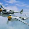
Focke Wulf Fw190D-13 1:48 Hobbyboss History Arguably one of the best fighters of the time, the Fw 190 was widely used during the Second World War. A total of over 20,000 were produced, including some 6,000 fighter-bomber variants. The 190 remained in production from 1941 until the end of the war, going through multiple redesigns. The Fw.190 made a name for itself as a true Luftwaffe workhorse and was used in a wide variety of roles, including a high-altitude interceptor (especially the Fw.190D), escort fighter, fighter-bomber and night fighter. When the Fw 190 started flying operationally over France in August 1941, it quickly proved itself to be superior in all but turn radius to the Royal Air Force's main front-line fighter, the Spitfire Mk. V. The 190 wrested air superiority away from the RAF until the introduction of the vastly improved Spitfire Mk. IX in July 1942 restored qualitative parity. The Fw 190 made its air combat debut on the Eastern Front in November/December 1942; though Soviet pilots considered the Bf 109 the greater threat, the Fw 190 made a significant impact. The fighter and its pilots proved just as capable as the Bf 109 in aerial combat, and in the opinion of German pilots who flew both, provided increased firepower and manoeuvrability at low to medium altitude. The Fw 190 became the backbone of the Jagdwaffe, along with the Bf 109. On the Eastern Front, and was versatile enough to use in Schlachtgeschwader (Battle Wings or Strike Wings), specialised ground attack units which achieved much success against Soviet ground forces. As an interceptor, the Fw 190 underwent improvements to make it effective at high altitude, enabling it to maintain relatively equal with its Allied opponents. The Fw 190A series performance decreased at high altitudes (usually 6,000 m (20,000 ft) and above), which reduced its effectiveness as a high-altitude interceptor, but this problem was mostly rectified in later models, particularly in the Junkers Jumo 213 inline-engine Focke Wulf Fw 190D series, which was introduced in September 1944. In spite of its successes, it never entirely replaced the Bf 109. The version this kit depicts, is that of the D-13 which was based on a D-11, Fitted with the up-rated Jumo 213F series engine similar to the Jumo 213E used in the Ta-152 H series but minus the intercooler. Two 30 mm (1.18 in) MK 108 cannons were installed in the outer wings to complement the 20 mm MG 151s in the inboard positions, but also fitted with a MG151/20 20mm cannon firing through the propeller hub. The Model This kit is the sixth Fw-190 released by Hobbyboss, and is based on the original D-9, released in 2013. The kit come ins a smallish, but quite well filled box, with an artists impression of a D-13 parked up at an airfield, which has obviously been captured, as the hapless pilot is being led away by a British soldier. Inside, there are eight sprues of various sizes, all in a light grey styrene, one sprue of clear styrene, a small sheet of etched brass, plus the decal sheet. As usual for a Hobbyboss kit, all the parts are well moulded, with no sign of flash or other imperfections, and only a few moulding pips. The instructions are very clearly printed and easy to follow, there being only eight steps to completion. Construction naturally begins with the cockpit and the fitting of the front and rear bulkheads to the single piece floor pan, complete with side consoles. Also fitted to the floor is the rudder bar, with its separate foot pedals attached, the joystick, lower instrument panel, with decal instruments, along with the seat and its supporting frame. The supercharger is then assembled, consisting of five parts it is then attached to the engine fire wall, along with the two piece oil tank. The exhaust stubs are fitted to each fuselage half from the inside before the firewall bulkhead, cockpit assembly, upper instrument panel, also with decal instruments, and four piece tail wheel assembly are sandwiched between the two fuselage halves. It is at thsi point when you realise that you not be able to see anything of the supercharger detail. The closed up fuselage is then fitted with the top forward decking complete with separate air intake, gunsight, PE rear canopy decking, horizontal tailplanes and rudder. The windscreen is then glued into position and the canopy, fitted with the pilots head armour and support, plus the three piece slider assembly, is also fitted. The main undercarriage bays are then glued to the single piece lower wing, the bays having been detailed with wing mounted cannon, plus centre and outboard cross braces. If the model is to be fitted with the various bomb racks, the holes of these will need to be opened up before the upper wing panels are attached. The trailing edge is fitted with separate flaps and ailerons, the wing tips fitted with clear navigation lights and the starboard wing tip with the pitot probe. There is a choice of cowling, one with closed gills and one with open gills, to be fitted to the nose of the fuselage. The wing assembly is then fitted to the fuselage assembly and it starting to look like an aircraft. Each main undercarriage is made up from a single piece oleo, bay door and wheel. Each undercarriage is then glued into position and fitted with a retraction actuator and spring unit. Whilst the model is upside down for undercarriage fitment, three aerials and the footstep are attached. The big fat prop is fitted with the separate backplate and spinner, before being fitted to the model, along with the large four piece intake scoop that is fitted to the starboard side of the forward fuselage. The model can be fitted with two bombs outboard of each undercarriage leg each bomb is fitted with two crutch pads and fitted to a pylon. On the centreline you can fit a quad bomb carrier. Made up from four bombs, again each fitted with two crutch pads, a four point stores carrier, with another pair of crutch pads and the long pylon. Decals Along with the instrument panels, the decal sheet carries national markings and unit markings for just one aircraft, that of Fw-190D-13, Yellow 10, W.Nr.836017, as used by Stab JG 26, based at Flensburg airfield. The decals are well printed with minimal carrier film. Ehy are slightly glossy, with good opacity and in register. There is a full set of stencils included, whilst the swastika has been printed in two halves, to get round the laws in some European countries. Conclusion This whole series of Fw-190s by Hobbyboss have been great little kits, maybe not as complicated, or some would say accurate as the Eduard offerings, but a nice kit none-the-less. Yes it’s a fairly simple kit, which can be a good thing if you’re trying to break modellers block, and also be a good kit to practice painting German mottle scheme for that bigger, more expensive kit you have in the stash. Highly recommended. Review sample courtesy of
-
Panzerkampfwagen 38(T) Hobbyboss 1:35 History The CKD (Praga) LT vz.38 design was straightforward and only based on well-proven solutions. The most distinctive features was its suspension, consisting of two-pairs of cold sprung bogies with massive road wheels. The size of these was seen as a benefit for protection, ease of maintenance and cost, compared to the over-complicated wheel train and suspensions system of the LT vz.35. It was an inspiration for the German designers of the Panzer II. However, they used a torsion arm system instead. The hull was mostly riveted, compartmentalized with the engine at the rear, and a transmission tunnel running to the front drive sprockets. The THN late export versions had three return rollers, but the LT vz.38 had two instead, the rear one being dropped and the relatively narrow tracks, lightly tightened. Armament comprised the fast-firing Skoda A7 37 mm (1.46 in) gun with 90 rounds, both HE and AP. It was flanked by an independent ball-mounted compact Skoda vz.38 machine gun, a second one being mounted in the bow. Total provision for these was around 3000 rounds. The TNHPS, or LT vz.38, thus designed was poised to enter service with the Czech army. On July, 1, 1938, 150 were ordered, but failed to be delivered because of the German invasion. Many vz.38s of the first original batch were later given to the Slovakian army. Although the Germans were impressed by the design, the Praga-Skoda lines were reorganized under their control, and the design of the new LTM 38 was revised while production was running. Modifications included a rearranged and roomier turret, holding a third crew-member, the commander being spared of any other tasks. Also added were an intercom system, a new German radio set, a revised commander cupola, modified sights, and new external fixations. These vehicles were renamed Panzerkampfwagen 38(t) in January 1940. Despite the fact that no less than eight main versions (Ausführung) of the Panzer 38(t) existed, not including the Ausf. S intended for the Swedish market, there are few differences between them, even to an exerted eye. The first Ausf. A (entirely riveted construction) was produced to an extent of 150 machines from May to November 1939, and the next batch of Ausf. B (110), C(110) and D (105) were produced from January to November 1940. They were very similar, except for some detail modifications, like external fittings, improved commander cupola, sights, a new headlight and a half-riveted, half-welded construction. But all had in common the main Czech Skoda KwK 38(t) L\48 gun and two vz.38 machine guns. Protection was slightly improved but was limited to 30 mm (1.18 in). The Ausf. E(275) and F(250), built between November 1940 and October 1941, were up-armoured to 50 mm (1.97 in), with an extra bolted-on 25 mm (0.98 in) appliqué armour on the frontal glacis. The turret mantlet and front were also thickened. New larger storage boxes and fixation points were added on the mudguards. The Ausf. S (May-December 1941) was an offshoot initially built for Sweden, but confiscated and incorporated in the Wehrmacht. The Ausf. G was the last “regular” version, with the same armour but better protection distribution and a nearly all-welded hull. This was the most prolific series, 321 being delivered by CKD-Praga from October 1941 to June 1942. 179 more were delivered as chassis and later transformed into SPGs. The Model This is another ex-Tristar kit, originally released in 2006, that Hobbyboss have re-boxed and released under their own branding. The kit keeps the same box art as the original, with just the Hobbyboss name replacing that of Tristar which makes them somewhat familiar. Now moulded in the now standard HB beige styrene the parts are well moulded, showing that the moulds are still in good shape, with no sign of flash of other imperfections, just a numerous moulding pips to worry about. In all there are seven sprues of beige styrene, three of dark grey and one of clear, with a smallish decal sheet completing the contents. The kit looks like it will quite a simple build, with only individual track links causing any bother. Construction begins with the assembly of the eight road wheels which come with separate tyres. The wheels are then attached to the four suspension units, each of which are made up from three parts. The wheels are kept on the axles by a large bolt head and cover plate. The sprockets and idlers are each made from five parts, whilst the return rollers are assembled from three parts. The lower hull is constructed is made from separate panels, consisting of floor, sides, rear bulkhead plus the upper and lower glacis plates, the upper section of which is fitted with a separate access panel. The wheel assemblies are now attached to the lower hull assembly along with the machine gun panel, which has the three piece machine gun, and two four piece outer vision blocks and five piece inner drivers block fitted. The two fenders are then attached to the lower hull, each fitted with the various pioneer tools, jack, jack block, aerial base and headlight. The turret and engine panels are then glued into position, along with the drivers hatches. A length of track needs to be assembled and fitted to the front lower glacis plate via the tie rod. The engine hatches are fitted with their respective PE grilles before being fitted to the engine decking. On the rear bulkhead, the large round access panel is assembled and glued into place, followed by the three piece exhaust which has a five piece stowage bin attached over it. Below the exhaust the two towing hitches are fitted and the reflectors are fitted to the rear of the fenders. The small grille to the rear of the engine decking is fitted with a PE grille before being glued into place. Assembly of the turret begins with the fitting of the three piece breech to the rear of the gun barrel and the mantel to the front of the breech section. The front plate of the turret is then fitted with the four piece co-axial machine gun and its ball socket, along with the three piece gun sight/vision block. The main gun is further detailed with the breech side pieces and trigger, followed by the trunnion mounts to which the gun is fixed to the front plate. The build then moves to the turret roof to which the commanders cupola, which is built up from ten parts, is attached, along with the aerial and grab handles. The turret itself is built up from the base, side and rear plates, plus a small plate at the front. To this the roof assembly is attached, along with the front plate, to which two additional side plate are fitted, one on each side of the mantle. Inside the turret two seats and the respective supports are fitted. The completed turret is then fitted to the hull completing the main part of the build. The kit does come with a couple of figures, although only one is used, that of the tank commander which comes as a single piece torso and legs, but with separate arms, personal equipment and a selection of three heads. The is also a pair of headphones which can be made up using the plastic and etched parts provided. Decals The decal sheet provides crosses, identification numbers and unit emblems for six vehicles, four in an overall panzer grey scheme, one in panzer grey and dark yellow and one in panzer grey with white distemper. Vehicle 833 of the 204th Panzer Regiment, 22nd Panzer Division, Crimea 1941/42 Vehicle 714 of the 204th Panzer Regiment, 22nd Panzer Division, Crimea 1942 Vehicle 525 of the 25th Panzer Regiment, 7th Panzer Division, Russia 1942 Vehicle 522 of the 204th Panzer Regiment, 22nd Panzer Division, Crimea 1942 Vehicle 243 of the 19th Panzer Division, Russia 1942 Vehicle 11 of the 10th Panzer Regiment, 8th Panzer Division, Russia 1941 The decals are nicely printed, with good opacity and in register. Since there are some awkward areas for the decals to sit the thin carrier film should settle down well with an appropriate softening and setting solution. Conclusion The Tristar kit garnered much critical acclaim when it was released and the change of ownership shouldn’t mean a change in quality. Not a difficult build, although the track links may cause some modellers a challenge, it should be fine for all but the newest of modellers, and a good introduction to 1:35 scale military vehicles. Very highly recommended. Review sample courtesy of
-
Panzerkampfwagen IV Ausf D/Tauch HobbyBoss 1:35 History The Panzerkampfwagen IV (PzKpfw IV), commonly known as the Panzer IV, was a German medium tank developed in the late 1930s and used extensively during the Second World War. Its ordnance inventory designation was Sd.Kfz. 161. Designed as an infantry support tank, the Panzer IV was not originally intended to engage enemy armour—that role being allocated to the Panzer III. However, with the inadequacy of the Panzer III becoming apparent and in the face of Soviet T-34 tanks, the Panzer IV soon assumed the original role of its increasingly vulnerable cousin. The most widely manufactured and deployed, fully turreted German tank of the Second World War (not including Germany's main assault gun) at some 8,500 examples, the Panzer IV was used as the base for many other fighting vehicles, including the Sturmgeschütz IV assault gun, Jagdpanzer IV tank destroyer, the Wirbelwind self-propelled anti-aircraft gun, and the Brummbär self-propelled gun. The Panzer IV saw service in all combat theatres involving Germany and was the only German tank to remain in continuous production throughout the war, with over 8,800 produced between 1936 and 1945. Upgrades and design modifications, intended to counter new threats, extended its service life. Generally, these involved increasing the Panzer IV's armour protection or upgrading its weapons, although during the last months of the war, with Germany's pressing need for rapid replacement of losses, design changes also included simplifications to speed up the manufacturing process. After manufacturing 35 tanks of the A version, in 1937 production moved to the Ausf. B. Improvements included the replacement of the original engine with the more powerful 300 PS (220.65 kW) Maybach HL 120TR, and the transmission with the new SSG 75 transmission, with six forward gears and one reverse gear. Despite a weight increase to 16 t (18 short tons), this improved the tank's speed to 39 kilometres per hour (24 mph). The glacis plate was augmented to a maximum thickness of 30 millimeters (1.18 in), and the hull-mounted machine gun was replaced by a covered pistol port. Forty-two Panzer IV Ausf. Bs were manufactured before the introduction of the Ausf. C in 1938. This saw the turret armour increased to 30 mm (1.18 in), which brought the tank's weight to 18.14 t (20.00 short tons). After assembling 40 Ausf. Cs, starting with chassis number 80341, the engine was replaced with the improved HL 120TRM. The last of the 140 Ausf. Cs was produced in August 1939, and production changed to the Ausf. D; this variant, of which 248 vehicles were produced, reintroduced the hull machine gun and changed the turret's internal gun mantlet to an external one. Again, protection was upgraded, this time by increasing side armour to 20 mm (0.79 in). As the German invasion of Poland in September 1939 came to an end, it was decided to scale up production of the Panzer IV, which was adopted for general use on 27 September 1939 as the Sonderkraftfahrzeug 161 (Sd.Kfz. 161). The Ausf D is the subject of this particular kit and one of the approximately 200 Panzer IIIs and IVs that were converted to be able to snorkel through rivers and lakes. The Model Having acquired the Tristar moulds around this time last year Trumpeters sister company Hobbyboss have finally started re-releasing the old Tristar kits. The first one arriving at BM Towers being the Panzerkampfwagen IV Ausf D/Tauch along with three others which will be reviewed in due course. Originally released by Tristar in 2006 the kit introduced new parts to the 2003 release of the Panzer IV Ausf C. The Tristar kit was pretty well received and although requiring a bit of care to build it was accurate with a very good fit of parts. Since Hobbyboss don’t seem to have altered the sprues in any way, (some sprues still have the Tristar name on them), the same should be able to be said of this release. The instructions are also the same, and whilst the modeller is able to effectively build four versions of the tank, the way the instructions are written, means that the modeller has to be very careful to use the correct parts for the particular version they choose. The four versions are; Panzer IV Ausf D – unconverted Panzer IV Ausf D Tauch – Combat mode Panzer IV Ausf D Tauch – Preparing to wade Panzer IV Ausf D Tauch – Fully prepared to wade Even the box art is the same as the Tristar packaging with the colour artists impression surrounded by a yellow boarder. As it is, all the parts are beautifully moulded, with the sprues and separate lower hull and turret in a sandy yellow styrene. There are forty eight sprues in total, if you include all the smaller sprues which are actually joined together. There are also three sprues of dark grey styrene for the track links, two of clear styrene, a medium sized sheet of etched brass, a length of copper wire and two decal sheets. There is no sign of flash anywhere, but there are quite a few moulding pips that will need to be cleaned up. This is definitely one of those kits where you’d be best to read the instructions beforehand and mark up the parts you are going to need to build up the particular version you intend to build. Since there are four ways to build this kit I will just write up the build for the fully prepared vehicle. Construction begins with the assembly of the thirty two road wheels, each of which is fitted with separate tyres followed by the individual suspension units, which are assembled from seven parts, ensuring that the correct parts are used as they are handed. Two pairs of road wheels are then glued to each suspension unit. The drive gearbox covers are then built up from three main parts and nine separate bolt heads, the bolt heads being at the ends of the parts that look like shell cases. The four piece sprockets are then fitted to each drive unit. The idler wheels are each made up from five parts, whilst each return roller consist of two parts. The lower hull is assembled next, with the sides, bottom, and rear bulkhead all separate parts. The hull is strengthened with the fitting of two interior bulkheads, whilst the hull sides are fitted with the individual bump stops. The underside of the hull is detailed further with the fitting of sixteen bolt heads and four brackets. The sprocket, idler, return roller and road wheel assemblies are then glued into their respective positions. The upper hull section is then detailed with the fitting of the front /front inner mudguard plates side armour panels, and viewing ports. These are followed by the fitting of the driver and machine gunners hatches, multipart machine gun mounting and frontal armour plate. To the rear the engine deck hatches, side and rear panels are attached, along with their associated grab handles, fittings and the rear mounted shackle brackets. The upper hull is then glued to the lower hull assembly, whilst the tracks are each assembled from ninety six of the one hundred and eight provided for each side. Back at e rear of the hull, the mudflaps are fitted with the reflectors before being fitted to the rear of the fenders. Also at the rear, the two exhausts are assembled, each from four parts, before being fitted to the rear bulkhead. The main gun/mantle is made up from twenty two parts, as the kit includes the breech section and spent ammunition basket. The gun assembly is then fitted from the front to the turret, to which the upper turret plate is then fitted, along witht eh loaders hatch. The kit provides a simplistic turret floor, which is attached to the lower turret section by three legs, two of which are fitted with folding seats, whilst a third seat is fitted to the lower turret section. With the floor attached the commanders cupola is made up from fourteen parts, before being fitted to the rear of the turret. The rest of the turret hatches are then glued into position, along with the various details, such as grab handled, handrails, Schürzen rails, vision ports and eye bolts. The port fender is then fitted out with the gun cleaning rods, jack rest block, track tool, shackles, fire extinguisher, step and various pioneer tools. The starboard fender is fitted out with the main jack, more pioneer tools, spare track links and the brackets for a long square post, (this item is not included in the kit, nor are there any references to as to what it is made of). The towing cable is then assembled and fitted to the brackets on the rear bulkhead and the kit finished off with the fitting of the turret. Decals The two small decal sheets are nicely printed, with good opacity and a nice thin carrier film. They provide the markings and unit ID codes/emblems for five different tanks, these being:- Panzer IV Ausf D, of 2nd Panzer Division, Semols, 1940 Panzer IV Ausf D, No.933 of 9./Pz.Rgt 18, Russia 1941 Panzer IV Ausf D, No.632 of Pz.Rgt. 18, Russia 1941 Panzer IV Ausf D, No.342 of 3./PZ.Rgt. 18, Germany 1940 Panzer IV Ausf D, No.231 of 3./PZ.Rgt. 18, Germany 1940 The second decal sheet also has Panzer IV Ausf D No.No.321 included, but this vehicle is not mentioned on the painting guide. Conclusion Whilst his is a very nice and interesting release, which when first produced by Tristar was pretty well received, it’s not without its problems. Not in the kit itself, but in the instructions. Great care will need to be exercised during the build, particularly in using the correct parts for the vehicle you wish to build. It’s also not one for the novice, but those modellers with a bit of experience behind them who should be able to produce a very nice model. Highly Recommended Review sample courtesy of
-
The last completed model of 2015. Represented as an F-84F from 311 squadron of the Royal Neterlands Air Force. The model is completed with the massive 450 gallon fuel tanks. The Royal Neterlands Air Force acquired a total of 180 F-84F Thunderstreaks. The kit is from Hobby Boss, the decals came from Dutch Decal F-84F Thunderstreak (48052) and colors used are from Vallejo Dark Sea Green (71.053), P.R.U Blue (71.109) and Dark Green (71.012). Thanks for looking. Jan Remco
- 10 replies
-
- 10
-
-
Source: https://www.facebook.com/TrumpeterModel/photos/a.103538733138062.8169.103526326472636/537476479744283/?type=3&theater So far really NEW in the 2016-2017 catalogue ref.81756 - Sukhoi Su-34 "Fullback" ref.81757 - IAR-80 ref.81758 - Sukhoi Su-17M-4 "Fitter-K" ref.81759 - Sukhoi Su-17UM-3 "Fitter-G" ref.81760 - Lavoshkin La-11 "Fang" For comparison quoted NEW in the 2015-2016 catalogue: 1/48th ref. 80379 - Messerschmitt Me.262B-1a/U1 Schwalbe ref. 80381 - Chance-Vought F4U-1 (early version) Corsair ref. 80382 - Chance-Vought F4U-1 (late version) Corser ref. 80383 - Chance-Vought F4U-1A Corsair ref. 80384 - Chance-Vought F4U-1D Corsair ref. 80385 - Chance-Vought F4U-2 Corsair ref. 80390 - Chance-Vought F4U-5N (early version) Corsair ref. 80391 - Chance-Vought F4U-5N (late version) Corsair ref. 80393 - Chance-Vought AU-1 Corsair ref. 80394 - Chance-Vought Corsair Mk.I ref. 80396 - Chance-Vought Corsair Mk.III ref. 81710 - Grumman A-6E TRAM Intruder ref. 81711 - Sukhoi Su-27 "Flanker-B" ref. 81712 - Sukhoi Su-27 (early version) "Flanker-B" ref. 81713 - Sukhoi Su-27UB "Flanker-C" ref. 81714 - Sukhoi Su-30MKK "Flanker-G" ref. 81715 - Shenyang J-11B ref. 81720 - Focke-Wulf Fw.190D-12 R14 ref. 81721 - Focke-Wulf Fw.190D-13 ref. 81731 - Northrop P-61B Black Widow ref. 81732 - Northrop P-61C Black Widow ref. 81734 - BAe Hawk T.Mk.67 ref. 81735 - BAe Hawk TMk..100/102 ref. 81736 - BAe Hawk T.Mk.127 ref. 81738 - BAe Hawk T.Mk.1/1A Red Arrows ref. 81740 - Lockheed U-2R Dragon Lady ref. 81741 - AMX ref. 81742 - AMX A-1A ref. 81743 - AMX-T ref. 81744 - AMX A-1B ref. 81745 - Saab J-29F Tunnan ref. 81746 - Saab J-29B Tunnan ref. 81747 - Focke-Wulf Fw.190V-18 ref. 81748 - Shenyang J-16 ref. 81750 - Messerschmitt Bf.109G-2 ref. 81751 - Messerschmitt Bf.109G-6 ref. 81752 - Saab J-32B/E Lansen ref. 81753 - MiG-31 "Foxhound-A" ref. 81754 - MiG-31B/BM "Foxhound-B" ref. 81755 - MiG-31M "Foxhound-B" V.P.
-
So I did this a little while for the "French Fancy" group build, but then never got round to posting up. First completed build of the year and also a genuine scheme worn buy the aircraft in question!
-
My hobbybossy Lws , i wanted to build something a bit different ,And to have some fun , was going to do a water dio with them fishing and drinking but liked the idea of the harbour . ps hand drilled out the vent holes in rear only 120 per side !
-
- 4
-
-
- land wasser schelper
- lws
- (and 6 more)
-
And so this flying barrell is finished: For those of you that have not seen my WIP, (here), here is a brief summary of this model. And let us start with the positive side. First: It looks like a Tunnan. And maybe that is the most important thing. AZ Models J 29 did not. Fit is also terrific, no problems at all, which makes it very easy to build, almost a weekend project. Surface detailing is fine and crisp and panel lines are correct. Cockpit is fairly good detailed as well as the wheel wells. It has a nice boxart, and the box is also very nice, made from - what I can see - very reliable cardboard. The plastic bags that contains the sprues seems to be of good quality, and... and... OK. Let's switch to the dark side. Decals are the worst I have ever seen on this side of 1970. And although it looks like a Tunnan, it has minor shape errors almost everywhere - however you have to be a Tunnan expert to see them all (I could not). Most annoying is that the air intake is too large. Another shape error is a continuous line from nose to exhaust, the real Tunnan has a more flat belly. But hey, still it looks like a Tunnan. The worst error is however that it is too small, about 1/52 scale. A bit sad is that the main wheels and the ejection seat seems to be in 1/48. SInce the decals were useless, i used decals from my spares box. Some of them are in fact from different 1/72 sheets. I painted it with Tamiya colours, the green is a mix of a number of different green and grey shades. Most is OOB. The only additions are seat belts, the red handle on the seat and brake wires on the main gears. In a few weeks Pilot Replicas will release their version if the same subject. It will be much more expensive, but also much more correct (I have seen it, it is amazing!) and you do not have to fix decals on your own. Anyone who wants to build a perfect model of this iconic aircraft should turn to their release. But for those of you that find it is too expensive (HB's Tunnan is about 3/5 of the price of PR), want a fairly enjoyable build and are satisfied with a model that in most people's eyes looks like a Tunnan, this one could be a good choice. So to quote myself from the WIP thread: The conclusion for this model is that it, apart from the decals, is a terrific kit for all the lovers of 1/52 scale.
- 14 replies
-
- 14
-
-
 Here is my latest build both 1:48. Using the HobbyBoss and Italeri kits with Eduard BigEd sets for both, some scratch building where needed and painted with Vallejo Air. I know the pureists amongst you don't like the shape of the HobbyBoss nose, but I have to say its a far superior kit to the Italeri! I have had to use filters for the photos to get some half decent images, I can assure you they are not quite as weathered as they appear in the pics!
- 16 replies
-
- 16
-
-
Hi folks, Second of the early U.S. Navy schemed builds.Another Hobbyboss easy kit and one of their early releases which has the usual accuracy issues associated with this range but still scrubs up well,at least they have given us a clear glass insert for the under fuselage window's rather than the decal on the buffalo.If you have not had a go at one of these kit,s give one a go I,m in the middle of another Wildcat in a later wartime scheme,Many thanks for looking in.
-
Evening folks,with the 1/72 stash reduced to the being built Halifax and Lancaster and a yet un-started Boston I was perusing the hallowed pages of King Kit,s sale items and picked up a Trumpeter Il 28 Beagle(I know) ! for the silly sum of six quid,I normally order at around the Twenty quid mark so after Airfix's Widcat build thought I would give the Hobbyboss easy kit a go in the early yellow wings scheme so to make up the rest I ordered the Little Buffalo also in a pre-war scheme.Now I know these kits get some stick but for ease of building and general quality they're not half bad and quick to go together which suit;s me as that;s the part I like! So here's the boxes and tomorrow when I get the light I will post the sprue's etc. And for six Quid the Trumpeter Beagle is a cracking kit too!
-
5cm Pak(t) Sfl.Fgst. Pz.Kpfw.35R 731(f) 1:35 Hobby Boss The Germans in WWII fell into the habit of reusing captured equipment, which was always fun for spares and repairs, but led to some interesting cut-and-shut jobs appearing that probably shouldn't have ever got past the sketches on napkins after a glass or two of the local vino. After the capitulation of France, a number of Renault R35s found their way into Nazi hands, with some of them being used in general security duties where their obsolescence was less important. Others were converted to various tasks, and this particularly catchily titled "thing" was one such beast. Originally sporting a 37mmm Czech gun in a slab-sided casemate emplacement perched on the R35 chassis, this sub-variant was up-gunned with a German built 5cm piece with a longer barrel, which gave it more hitting power. Although it was comparatively well-armoured and well-armed in this guise, the type as a whole was used more in protecting territory than in the front line, mainly due to its poor speed over ground, and the constant arms race making it less formidable as time went by. There is very little information available about this variant, with most pictures relating to other variants with different armament options. The Kit In keeping with Hobby Boss's liking for the unusual, this kit is of a vehicle that saw little service in small numbers, and yet here we have a styrene injected kit of it, and not only do we have the exterior, but we have a fairly comprehensive interior to boot! The kit arrives in a fairly compact top-opening box, which is full to the brim with over 500 parts. There are eleven sprues in a sand coloured styrene, two sprues in brown styrene containing tracks, and a solitary upper hull part in the sand styrene. There is also a sheet of Photo-Etch (PE) brass, decal sheet, instruction booklet, and separate colour printed painting and markings guide. The first thing that impresses is the sheer number of parts, and that the designers have managed to squeeze so much detail into such a small chassis. Then you look at the top heavy chassis and you might have a little smirk, as it reminds me of the similar Bison that sits up and begs whenever it is fired. When that moment of levity has passed, poring over the instructions shows that there will be a lot of painting to do as you go along, with an almost complete interior, the gun breech and mount, as well as the open-topped gun shroud that invites the viewer to look inside. You'll need to plan the build with that in mind, and once the interior is complete, there will be some masking to protect the effort you have applied there. There is always the option of the canvas "tent" that could be applied to the top to keep the weather out. You could sometimes see these stowed to the rear of the casemate, so with the addition of some rolled out Sculpey or similar, you could reduce your workload by covering over the interior. The engine is first to be constructed, with a two part block that is heavily detailed with additional parts, a great many of which are absolutely tiny, which conspires to give you a very nicely depicted motor for your R35 chassis. Work then commences on integrating the engine with the lower hull, beginning with the sand-cast rear bulkhead, which has the idler tensioning devices and towing hook added, after which the radiator, cooling fan and ducting are assembled with the power-take-off wheel projecting from the rear of the box. The hull itself is made up from two side panels and a floor piece, into which the radiator housing, a styrene/PE stiffening plate and driver controls are added. The side panels are fitted out with three return-rollers and a final drive housing per side, and four bogies with two wheels per housing and a big suspension spring are built up. Two more solo bogies, two drive sprockets and two idler wheels are also constructed, and are installed on the suspension mounting points on the hull sides. At the same time the driver's seat, fuel tank and engine-mount bulkhead are ensconced within the hull, and the rear bulkhead closes up the rear. After adding a few more driver controls and their linkages, the drive-train is dropped into the hull, with a transmission housing added to the front, and driver-shafts to the sprockets complete the drive-train. Tracks. Given their small size in 1:35, HB have decided to go down the link and length route, and I can't say I blame them. The straight track runs are made up from six parts with a few links in between the curved lower sections, and twelve individual links at each end. Each of the individual links have three sprue gates, while the lengths have additional dead-end tabs that ensure against short-shot links, and also double as ejector-pin positions, saving the delicate detail from marring by mis-alignments. Unless you're going to the trouble of using metal replacements, these should do you proud with a bit of sympathetic painting and weathering. Give them a rub with an artist's pencil to impart metallic sheen where they get worn, and you'll never know they weren't metal. With the tracks in place, the full length fenders are added, along with a little stowage and a big bottle-jack on the right rear. The upper hull is a very nicely moulded single part with a rather too-fine casting texture that you might want to augment with a stiff brush and some Mr Surfacer. The off-centre transmission housing cover is added to the right side, while the driver's two-part hatch is placed into the right side, with the option of having his flip-up vision port open if you choose, by swapping one opener for another when adding the instrument panel and hydraulic prop to the underside of the upper hull. At this point the upper hull is glued to the lower, hiding away most of the detail in the very rear of the hull. The side-mounted exhaust muffler and a set of pioneer tools are added to the port side, and on the starboard a small vertical panel with what looks like a starter handle fits to the rear corner. The casemate surrounding the gun is built onto a separate floor that sits on top of the original hull, but first the 50mm gun must be built up. Like the engine, it is high on parts, with a horizontally split barrel and multi-part breech sat upon the mount and recoil mechanism. Elevation and traverse mechanisms and a rather simple iron-sight are glued to the mount, and a number of bracing tubes are added to the sides to support the dual-layered inner gun-shield. The outer casemate shield is then decked out with equipment such as ready-rounds, pistol holster, ammo pouches and a gasmask canister, plus the sighting hatch cover. The floor to the compartment is then flipped over to install the fillet that allows it to fit neatly to the curvy cast upper hull, with a number of short brackets supporting the overhanging bustle. Righting the floor allows the fitting of the radio box and other internal details, before adding the large ammo boxes that fill the bustle area and explain the bustle supports you added earlier! The gun mounts on a pair of holes in the floor, and the casemate front slides over the barrel and mates with the edge of the floor panel, as does the rear bustle. You may have noticed a pair of sprue protectors around the sharp front of the bustle part, as it tapers to a point and could easily be damaged without them. Take these off and clean up the gates at the last moment, or you might find yourself regretting it. Two crew access doors on the sides fill the gaps, and could be posed open if you wanted to show off your hard work, and that just leaves you to glue the casemate to the hull. Markings HobbyBoss aren't overly generous with markings at times, and given the lack of information that's available on this variant of a lesser known Beutepanzer, it's hardly surprising that the instructions show a Panzer Grey scheme and you get a set of four white crosses with two rows of white numerals from 0 to 9. For some unexplained reason there's also a set of white crosses with sand coloured centre lines. They're not shown in the markings guide either, which is odd. The decals are printed in-house, and look to have good colour density and sharpness, while the sandy crosses are in good register – not that it matters! Use one of the spare numbers or crosses to test their light-fastness, and double up with other spares if any grey shows through. Conclusion A nicely detailed weird little tank that has a lot of parts in the box when you consider how small it is, even after the casemate was grafted on. Even though it wasn't one of the best designs of WWII, it's still a personable tank, and well worth a punt if you like to model off the beaten track. Highly recommended. Out of stock at time of writing Review sample courtesy of
-
Russian BM-13N "Katyusha" Rocket Launcher 1:35 HobbyBoss Stalin's Organ as it was known in WWII was a truck chassis with cab where the flatbed had been replaced by a rack of rocket launch tubes that contained various diameter rockets over the years, as well as differing numbers of tubes, range and explosive power of the rockets. They were useful at delivering a lot or ordnance to a location rapidly, but suffered somewhat in accuracy due to their unguided nature and the variability of their propellant efficiency. Their ability to relocate between salvos was a plus, giving them the ability to hit fast and hard, then escape retribution by relocating, which offset their long reload time. The BM-13 was a WWII variant, although they continued in service long after cessation of hostilities in various guises, using various chassis. They were often built on lend-lease trucks such as the Studebaker US6 or post war the indigenous ZiS-151 (a rough US6 copy), and fired 13.2cm rockets weighing in at 42kg each from eight launch rails. The Kit This is a new tooling from HobbyBoss, and represents the post WWII BM-13N mounted on a Zis-151 that bears a striking resemblance to the Studebaker chassis, having some minor differences around the engine cowling at the front. Even the engine was copied to a large extent, much of which is replicated in the kit. If you are planning on building a WWII Katyusha, this kit won't be strictly accurate to the time period, but a great many folks won't know it wasn't produced until 1948. Inside the standard HB box are ten sprues, two truck parts off sprues, plus eight launch rails all in sand coloured styrene, a clear sprue, twelve flexible styrene tyres, two sheets of Photo-Etch (PE) brass, a decal sheet, markings guide on glossy colour stock, and the instruction booklet in black and white. On unpacking the sprues from the myriad of bags that protect every part of the kit, detail is good, with lots of small parts, some very nicely moulded larger parts that take full advantage of the available modern moulding techniques such as slide-moulding. The cab body is a single piece, as is the shroud that flips down for firing, and the launch rails have detail on all sides, including the lightening holes on the sides. Construction begins with another set of rails however, which are the chassis rails, because you get an almost full rendition of the vehicle inside the box. Cross-braces, transfer boxes and drive couplings are added first, with exhaust and suspension details after, including some lovely leaf-springs and hubs, onto which the wheels are placed. Each wheel has a two-part hub that fits inside a nicely done tyre that even has maker's mark and specification moulded into the sidewalls, as well an aggressive V-tread on the contact surface. The two rear axles are doubled-up by the use of handed hubs, while the single-width steering wheels are installed on a through-axle with steering gear and a transmission shaft added along the way. The engine is built up from a large number of parts, and should look impressive painted and weathered with oil and dirt. The engine and radiator assembly are added to the front of the chassis, while the battery box and fuel tank are fixed to the outside of the chassis rail along with some perforated crew steps on sturdy brackets. The cab is then built up on a floor panel, including; foot pedals, steering column and gear stick; instrument panel with accompanying dial decals; and a full-width bench seat for the crew. It is inserted into the underside of the cab, with the addition of glazing front and rear, with additional clear parts added between the inner and outer cab door skins. Separate windscreen wipers are installed in the top frame of the windscreen, and the bonnet/hood is then built up from a finely moulded set of panels, the sides for which have perforated louvers in their sides. The radiator grille is multi-layered, and includes the Cyrillic manufacturer's mark on the front for good measure, with large swooping fenders added over the front wheels. The flatbed consists of a floor panel that includes the rear fenders with light-clusters, plus several stowage boxes and a pair of spare wheels in a large and well detailed bracket that holds them vertically behind the cab. The rocket launch assembly is next to be constructed, beginning with the base, onto which the upstands and substantial tubular frame are built up over a series of steps. The eight launch rails and their rockets are constructed and linked together by three rods that hold them together, resting on cut-outs in the top of the support frame, which are glued in place with small shaped covers. The sighting equipment is then attached to the left side and the whole assembly dropped onto the rear of the truck, with a choice of travel mode or firing mode, by using a shorter or longer brace at the front of the supports. In firing mode a single-piece armoured cover is placed over the top of the cab to protect the windows and occupants from the hot exhaust gases, but this isn't shown in a stowed position for the travel option. These seem to vary in design somewhat according to available information, so check your references before you decide how to portray it. Markings The single-pages guide shows only one example, wearing Russian Green and a red star on each door, but as you can see from the decal sheet, there are other Soviet nations included on the decal sheet for your use if you feel the urge, although the Polish checkerboard looks a little out of proportion, so you'll need to check that too. Decals are usual HB, with reasonable register (looks like blue is out a fraction), slight stepping in some places, but usable. Conclusion A nice kit that needs to be set properly in a time-period, as I suspect some might think buy it thinking they're building a WWII era kit. Detail is excellent, and the use of PE is nicely done, but the decals are a bit of a damp squib overall. Recommended. Review sample courtesy of
-
The kit is intended to simulate louvres and meshes on aircraft models F/A-18C/D (Late) in 1/48 scale produced by Hasegawa and Hobbyboss. Made of steel with a thickness of 0.05 mm.
-
The kit is intended to simulate louvres and meshes on aircraft models F/A-18A/B and Early C/D in 1/48 scale produced by Hasegawa and Hobbyboss. Made of steel with a thickness of 0.05 mm.
-
 My contribution and first ever build on Britmodeller will be Hobbyboss`s V100 Armored car. I am predominantly an armour modeller and seem to be swaying towards military police subjects at the moment. I am using the "Improved product" version of the V-100 or M706 as it is sometimes called. I have a part built Vietnam version in the stash but am not entirely happy with it. The kit I am using contains all the parts required for the earlier version. The V100 was designed as a high mobility armored car to product freight convoys in unsafe areas of Vietnam to protect against attack by the Viet Cong. I am also using some decals from Echelon Fine Details of a car assigned to the 720th Military Police Battalion and called "Abraxas" Those of you who know your classic rock will know that this is a album by Santana and typical of its time.
 -
Hi! Can I join in? I need to get my modelling mojo back and this GB ticks all the boxes: Interesting time period: Vietnam War Interesting subject: F8F Bearcat - Last of the Grumman Piston Planes Easy Build: Hobbyboss 1/48 Bearcat OOB Here's what I'be building and the reference I'll be using (yep - that's it!) The kit comes with decals for a F8F-1B Bearcat from GC 1/22 'Saintonge', Armée de l'Air stationed at Dien Bien Phu airfield january 1954 (according to my reference! ) I plan on building OOB only adding seatbelt, antenna etc. Keeping it simple is of utmost importance for me at this stage, as I've had some modelling setbacks lately. ...and need to get back in the saddle! Is this OK with you? Cheers Hans J
- 5 replies
-
- 4
-
-
- Vietnam II Group Build
- 1/48
- (and 3 more)
-
Russian T-38 Light Tank HobbyBoss 1:35 History The T-38 was derived from the T-37 amphibious tank, itself based on the Vickers amphibious tank purchased from Great Britain in 1930. Perhaps it was also influenced by the French AMR-33. The Vickers was quickly modified into the mass-production T-37A. By 1935 the model had already shown many shortcomings which needed a solution in an improved model. Zavod n°37 in Moscow studied a replacement and eventually a prototype was constructed that year. The range of modifications was rather limited. The turret and driver positions were shifted (from the left side to the right), friction couplings were added to transmit power to the tracks and a new, vibration free, running gear suspension was added and perfected for better driving and crew comfort. Moreover, the T-38 was sightly simplified, lower, lighter, slightly larger and buoyancy characteristics were also better. The Zavod 37 R team choose to not deviate greatly from the original model and only applied a set of modifications to improve, most of all, the handling, driving and mobility characteristics on all terrains. It was thought the firepower could be improved greatly by fitting a 20 mm (0.79 in) SchWAK gun in the drivers compartment, in a fixed position, but the solution proved far too cumbersome and was only briefly tested. The T-38 hull was substantially lowered, with the upper superstructure almost blended with the lower hull and widened at the same time. So were the hollow mudguards to improve buoyancy as well as the handling in water. The double-drive system was unchanged as well as the Ford-derived GAZ engine, transmission, gearbox, drive sprocket and idler configuration, but friction couplings were added. A small three-bladed propeller screw did the job when submerged and, in shallow water, the widened tracks provided more underwater grip and friction surface. On land attention was focused on the sprung bogie suspension, which was substantially reworked to reduce the vibration level at high speed. The larger tracks also lowered the ground pressure. The shifted driver/commander positions improved driving visibility and handling (optimized for right-hand drivers). The hull was made of light rolled steel plates bolted on a frame, specially sealed. Protection was unchanged, as well as the armament, the usual belt-fed DT machine-gun. No provision was made for a radio. Production started at Zavod 37 in 1936 and was discontinued in 1939 when it became apparent that the lack of a radio and the firepower were two major issues, later corrected with the T-40. Numbers built differ greatly from source to source, ranging from 1200 to 1500 units delivered and put into service before the war started. In 1936 a handful of these vehicles were displayed during the May Red Square parade, under the belly of TB-3 bombers. Numerous exercises were performed for deep battle operations and each paratrooper unit was allocated 50 vehicles, and infantry battalions 38 vehicles each. The T-38 entered service in 1937 and showed that, in operations, the lack of radio was a major flaw. Once the radio-equipped vehicle of a platoon was destroyed, the unit had no means to communicate the enemy position, except to physically dispatch a vehicle to the HQ. Plus, the lack of protection and armament meant that in most encounters with an enemy their military value was scarce. Their first mass-engagement came in Finland, especially in the summer because of the swampy and marshy terrain. But they proved that even machine-gun bullets could pierce the armour and these were gradually phased out when the all-out improved T-40 was introduced in 1941. By the time of the German invasion, many seem to have been transformed into dug-out pillboxes in fixed positions on various lines of defence. Large numbers were destroyed, but an equally large numbers were captured, either by the Finns, for their own use, or the Germans which turned them to the Luftwaffe for guarding their advanced airfields. The Model The kit is packaged in the standard Trumpeter style top opening box with an artistic representation of the tank emerging from a river, much like the T-37A kit reviewed HERE. The difference is that this box has to be the absolute minimum size that Hobbyboss could get away with, being about 2/3rds the size of the T-37A box. Inside, there are eight sprues, a separate lower hull and a separate turret, all in a pale beige styrene. There are also seven sprues of brown styrene, one small sheet of etched brass, a length of brass wire and a small decal sheet. As with the previously reviewed kits from Hobbyboss, the mouldings are very well produced, with no sign of flash or other imperfections and only a few moulding pips. The details are pretty much as per the T-37 kit, in that they are well rendered with some very nice rivet detail. It also shares the same track system as the T-37, with the individual track links, which, whilst well moulded are joined to the sprue are three points, so not only will they take quite a bit of careful cleaning up, they will need a lot of patience putting a full run of eighty six links per side together. As with the T-37A kit, construction begins with the assembly of the road wheels and their suspension parts. Each pair of wheels is made up form eight parts and there are two pairs fitted per side. The difference is that with each of the bogies there is a length of brass wire, bent to shape with a mould provided, fitted between each upright. These assemblies are then fitted to the lower hull section, along with two return rollers per side and the idler wheel axle bearings. The sprocket wheel gearbox covers are attached followed by the sprocket wheels themselves. At the rear of the hull the propeller shaft housing and propeller are fitted, as is the propeller guard on the underside of the hull and a towing hook assembly with the rudder fitted between them.. The idler wheels are then attached and the assembled tracks can be fitted. The towing shackles on each side of the rear panel are made by the modeller bending the brass wire to shape, using a suitably shaped mould provided on the sprues. The upper hull is then glued to the lower hull and the separate engine cover, with added PE mesh grille and crew access hatch fitted. The two fenders are attached to the hull, whilst the horn and various brackets are fitted to the upper hull. The tow cable is fitted to the right hand fender and other fittings fitted to the left hand fender. The two, two part headlights are then attached to the front of each fender. With the pioneer tools fitted the two part exhaust is attached to the rear engine deck and a two piece storage box fitted to the right hand fender. The simple machine gun turret, with separate base, is fitted with the single piece machine gun, turret hatch and two PE plates. The external section of the machine guns ball socket is glued into position, meaning that the machine gun cannot be posed in anything other than straight without modification. The completed turret is then slotted into position on the hull, completing the build. Decals The small decal sheet only provides two sets of markings for the two vehicles provided on the colour chart. Both of which are in overall Russian Green, which is a shame, as there are quite a few colour schemes that could have been chosen, including those for the captured Finnish and German vehicles. although the Finnish swastikas are included in a split form. There is quite a lot of information on these schemes on the internet, so it shouldnt take long to find a different scheme for your model. Conclusion Yes, its yet another small Russian tank from Hobbyboss. They must be reaching the limit of production types by now. At least they are different enough to have a small squadron of them in your collection, and they do look rather cute, especially if posed next to a monster T-35. Now theres an idea for a diorama. Highly Recommended Review sample courtesy of
-
Hello! After a long forced absence from the workbench I managed to get this one finished at last. This is the Hobbyboss 1/48 F/A-18C Hornet built with the aid of Two Bobs decals and a scratched seat harness from me. Painted with Lifecolour/Tamiya acrylics and weathered with my own wash and an oil paint dot filter. Markings are that of the USMC Squadron VFMA-122 "CRUSADERS" Hope you enjoy the model.
- 36 replies
-
- 34
-
-
Schneider CA - Armoured 1:35 HobbyBoss Development began on the first French tank in 1914 at around the same time as the British were working on their Mark.1s. Although it lacked a turret and was plagued by similar reliability problems to the British, it was still pressed into production, despite having some serious design deficiencies that limited its usefulness. It was armed with a 75mm cannon and two Hotchkiss machine guns, with the cannon on the starboard side, which limited its field of fire as well as forcing a kind of broadside manoeuver in order to draw a bead on targets on the vehicle's left side. It is easy to confuse it with the larger St Chamond that followed it, and this too suffered from some of the same problems. The sloped frontal armour of the Schneider was initially effective, but once the enemy started using armour-piercing bullets, an additional 5mm spaced armour sheet was added to strategic places, which of course increased all-up weight, putting more strain on the 60hp engine. The overhanging "bow" was also an impediment to getting over rough ground, and the internal fuel cells were moved outside the hull after a number of tanks exploded due to hits in that area. The type saw action until the end of the Great War, but due to its flaws, any further development was cancelled, leaving just the remainder to be converted or scrapped. Six tanks were used by Spain, but were soon withdrawn when their uselessness became apparent at the beginning of the civil war. One original example in running condition survives in Saumur in France, which is the oldest functioning tank in the world. The Kit The early model without the improvements was released first, with this tooling variation bringing up the rear, just like the real thing. It is just what the WWI tank lover needs to add to the growing stable of Great War armour that surely now qualifies as a golden age of WWI modelling. The kit arrives in a compact box in usual HobbyBoss style, with an internal divider keeping parts movement to a minimum during transit. Within the box are five sprues, tow hull halves and two armour panels in tan styrene, four sprues of track parts in brown, two sheets of Photo-Etch (PE) brass, decal sheet, instruction booklet and of course the painting guide. Looking over the sprues, it's a well-detailed kit of the exterior of the vehicle, with plenty of slide-moulding evident at the edges of the sprues and on the hull parts to add extra detail without increasing the part count. The second large fret of brass is actually a rather nicely etched emblem commemorating the Great War, with the words World Peace under a British Mark IV tank with some Tommies trudging past. A very nice little extra that would look good attached to the base of a diorama. The date has been done in a reverse format though (YYY-MM-DD), which detracts a little bit from the overall effect to both British and American audiences. The caterpillar track sponsons are first to be built, both of which are split into front and rear parts which are joined once the road wheels and suspension parts are added. A ladder containing five return rollers attaches to brackets at the top of the sponsons, the axles for which slot into the lower hull. A pair of triangular fairings house the final drive for the rear-mounted drive-sprocket, each one made up from five separate parts. The tracks are individual links, each of three parts that are first glued together, then made into runs of sixty four links after the glue has set. The track can be tensioned on fitting by rotating the swing-arm on the sprocket before gluing it in place. A bracing strut is also added to the underside of the hull at this point, improving rigidity of the tracks. The upper hull is substantially complete as moulded, with only a few panels missing, which are added along the way, together with the fuel tanks mounted either side of the aft hatch, and a spinal hump that extends over most of the roof panel. A rear unditching "shovel" is attached to the rear box frame, and the additional spaced armour is added to the sides along with a PE grille on the nose. More armour is fitted to the vertical section behind the nose, and the driver's double-layered vision panel covers his hatch at the front. There appears to be a goof in the instructions at this point, as the panel with the circular machine gun mount just appears in place with no mention. It then disappears again until later in the build. The main gun is mounted in a hemispherical(ish) mount, as are the two Hotchkiss guns, and the 75mm cannon gets a full breech with controls tucked away behind. The machine guns are mounted on substantial curved brackets that could be left unglued in their mounts if you wanted the guns poseable. The main armament is glued to the starboard sponson floor and the upper hull fitted over it, so that it projects from the angled panel next to the driver's ear, after which it has a piece of additional armour added to the mantlet. The two secondaries fit onto mounts further back on the sponson floor, and are covered by the panels with circular cut-outs. More spaced armour is added under the nose, and a long exhaust runs from the front-mounted engine bay to the very rear of the tank where it kicks up vertically to vent above the roof level. Markings There are two markings options included in the box, each covering one side of a sheet of glossy A4 and printed in colour. No details are given other than the serial number, so a little digging will be needed if you'd like to know where and when they appeared during the war. From the box you can build one of the following: 61213 in dark yellow, red brown, navy blue and dark green camo, with black delimiting lines. 61024 in dark yellow, red brown and dark green camo, a white diamond with red circle within and the words "Fee Kaputt" on a white flag-style background painted on the rear fuel tank. The decal sheet is barely bigger than a large postage stamp, but as it only contains eight decals it's to be expected. Colour density, registration and sharpness are good, and the carrier film is of the thin glossy type. Conclusion If you missed the early mark like I did, just fancy the updated version sporting a very early form of spaced-armour, or just like WWI armour, then this is a great little kit that won't take you too long to put together, but gives you plenty of scope for painting and paint effects. Highly recommended. Armoured Early Review sample courtesy of
-
Sd.Kfz.221 Leichter Panzerspahwagen (1st Series) 1:35 HobbyBoss Based on a heavy duty off-road chassis from Horch, this light armoured car was used in reconnaissance battalions with varying degrees of success. Where there were existing road networks it excelled, but in rough or desert terrain it was less successful, which led to its early replacement with alternative vehicles. Production ceased early in the war, to be directly replaced by the uprated and more heavily armoured Sd.Kfz.222 with a 30mm cannon. It was crewed by two men, and lightly armed with a single MG34 machine gun, and protected by 8mm rolled steel armour that was protection only against rifle and other small arms fire. The best defence was to get out of harm's way using the 90hp Horch V8 engine that drove all four wheels from its position in the rear of the vehicle. The Kit This is a new tooling from HobbyBoss, and on first inspection it appears to be quite expensive considering the size of it. When you open the box however, you realise that a lot of effort has been expended in the tooling, as there is a lot in there to justify the price. There are thirteen sprues plus two hull halves in sand coloured styrene, a small clear sprue, four flexible plastic "rubber" tyres, two sheets of Photo-Etch (PE) brass parts, a decal sheet, instruction booklet and separate colour painting guide in the box, with a divider helping to reduce the chances of damage during transit. There is a full interior as well as a detailed chassis and engine, with lots of detail throughout to keep you busy. Construction begins with the big lump of a V8 engine, which is well detailed and includes the radiator and cooling fan, which is mated to the chassis along with the four-wheel drive-shafts, suspension linkages and coil-springs, with cross-braces and sub-frames for the axles. It really is detailed under the bodyshell, and is finished off by adding the four wheels, which consist of two hub halves and an inner cap each, pushed through the tyre to seat on the rims. A further two-part hub-centre is added before they are pushed into place, and if you apply the glue sparingly into the inner cap, you should end up with wheels that will rotate freely. The lower hull has a section of floor missing to accommodate the engine, and is festooned with PE brackets for stowage, as well as an MP40 and short-handled axe, driver foot-pedals, hand-controls, and various boxes of ammo and supplies. The PE brackets are filled with potato-masher grenades on both sides, with MG34 ammo and gas-mask canisters added for good measure. The driver's position is relaxed, with a tubular framed chair, and a curious reverse-angled steering wheel that must have taken some getting used to. The engine firewall is added behind the crew area, and on the outside a large shaped stowage box, covered spare wheel, and the two crew-hatches are added, although you can leave one or both open if you wish. With the hull attached to the chassis top, the radiator assembly can be added, and the upper hull is then detailed inside with hatches, vision-blocks, pioneer tools and a firer extinguisher. On the exterior hatch outer panels are added, with mesh panels covering the flat top section of the deck, and bullet splash strips around the turret and hatches in PE. The lower hull is finished off with additional armour panels and towing shackles, then mated with the upper hull, using alignment pegs in each corner to assist in making a good seam. The fenders are built up off the hull, and have additional fuel cans, jack, and width indicators added before they're slotted into the holes in the hull sides. The turret is built up on a central assembly that has a conical section and bracing struts that attach to the underside of the shallow open-topped turret. A crew seat is attached, and the turret walls have the choice of an alternative with two extra side view panels. The completed assembly is dropped into the hull and a nicely detailed MG34 is placed into its mount, with an additional anti-tank rifle lashed to the vehicle side. The turret is topped with protective mesh panels at the frot that open in a clamshell manner, while leaving the rear section open for the crewman to poke his head out if he dare. The last job is to add the two headlamps to the front, which have large clear lenses supplied in the box. Markings As is often the case with HobbyBoss kits of this nature, only one decal option is included, which is Panzer Grey and has the number plate WH – 66322. Other blank number plates are included however, along with the necessary numerals, so that you can make up your own. The decals are printed in-house, and have good register, colour density and sharpness. They are predominantly black, with white plates and crosses, but the instrument panel decal has some red accents to brighten it up. Conclusion These low-key kits from HobbyBoss are often surprising in terms of detail and the sheet quantity of stuff in the box. This one is one of those kits, and you can go to town with painting the details, without taking up too much room in your cabinet afterwards. Highly recommended. Review sample courtesy of
-
Me.262A-2a 1:48 HobbyBoss The 262 was the first production jet fighter of WWII on any side, and gave a pretty good account of itself, all told. Thankfully for the Allies, it was delayed hideously by Hitler's insistence that it should also be able to carry bombs, as well as the advances in metallurgy that were needed before they could get sufficient reliability in the engines to make jet powered missions practical. There are a plethora of variants that were either planned, proposed or in development, while only a few types actually saw service. Of the fast bomber or Schnellbomber variants, the A-2a was the definitive in-service variant, which was the "Sturmvogel" that Hitler so obsessed with, to attack the expected invasion beaches with little in the way of retaliation due to the Sturmvogel's speed differential. This insistence helped the Allies immensely, leaving fewer fighter variants to attack the incoming bombers and fighter bombers supporting the invasion. The A-2a had only the lower two 30mm Mk.108 cannons in the nose for defence/offense, and had two mounting points for either 250kg or 500kg bombs under the nose. The Kit This is one of the latest editions from HobbyBoss in a long and growing line of kits that represent great value, as well as providing plenty of detail into the bargain. The kit sprues are modular to squeeze best value from them, and if you've seen one kit, you've seen the majority of the parts already, so you'll know what to expect. We've reviewed a few of the previous kits already, and you can see the A-1a/U1 here and the B-1a here if you need a refresher. Although the box art sometimes lets them down, the contents of the box does not, and this variant even includes some decent box art painted by forum member Kostas Karvathias no less! Inside the box are ten sprues of various sizes, two small clear sprues, a metal nose-weight/gear bay part, decal sheet, the instruction booklet and separate colour printed painting guide. The build is as you'd expect, with a cockpit tub that has plenty of detail and also forms the inner section of the main gear bays. The gun bay shows all four Mk.108s installed, but only the bottom two were carried in reality, so you could either leave them out and add some more nose weight, or put them in anyway. The upper gun troughs in the nose are shown blanked over in contemporary photos, and you're incited to use part P9 that has them covered by a flat fairing. If you were going to leave the gun bay panels open (which is an option), you'll need to do some research to check how the open bay looked without the cannons. The bay is fitted to the top of the nose gear bay former, which is a chunk of white metal to provide nose weight, although there is a styrene equivalent left on the sprues. The nose gear leg can be added now with a choice of smooth or treaded tyres that also require different strut parts, but share retraction struts and door parts. Before the fuselage can be closed around the two assemblies, a quantity of parts are added to the rear fuselage in the shape of radio gear and other small parts, which only will be seen through a small bay door on the fuselage side if left open. The interior of the fuselage has been moulded with ribbing detail to accommodate this option, so check your references and add any wires and extra parts that you think will be seen through the open hatchway. Oddly, the interior of the engine nacelles also have the same ribbing moulded-in, but none of this will be seen with the intake bullet and exhaust cones installed and their fairings added front and rear. It's possible that they're either a hangover from a more ambitious earlier nacelle design that included opening panels, or that the rigidity that they imbue to the parts is desirable. Needless to say, you build up two nacelles, which are handed left and right, but once complete they are difficult to mix up due to their angled exhaust fairings and keyed joints. The lower wing is full width with cut-outs for the engines, and this is joined to the two upper wing panels, leaving a gap where the fuselage will sit, which receives some additional detail parts for the main gear bays. Check the fit of the fuselage in the wing assembly, and fettle as necessary, after which you can add the nose cone and cowlings to the nose, and then the rear deck behind the pilot plus his three part canopy, consisting of a windscreen that has a small section of the surrounding fuselage moulded-in, the canopy opener, and the fixed rear section. A piece of bullet-proof glass is added inside the windscreen, and head armour is inserted inside the canopy, which can be posed open by leaving the attachment lugs on the starboard side. The engines are installed under the wing, and two panels under the nose that contain the location points for the bombs and shell ejector chutes finish off the fuselage. The main gear legs have separate oleo-scissor links and retractor jacks, plus a two-part captive bay door on each leg, with the inner doors hinging together on the fuselage centre-line. The large nose bay door has its own retractor part, and that's the basic build completed. The Sturmvogel's main purpose was to drop bombs, and these are included in the kit, with 250kg or 500kg options both in the box. The bombs are in two halves, with fin braces added at the rear from slim styrene parts, while the stubby pylons are made up from two halves, the smaller ones having separate sway-braces. It's your choice which size you use, or you could leave the pylons un-loaded. Markings The Luftwaffe were keen on mottle to help camouflage their aircraft against Allied attacks, and the two decal options provided in the kit make heavy use of these techniques, but one is easier to carry off than the other! From the box you can build one of the following: Me.262A-2a White Y of I./KG51, 1944/1945 – RLM82/02 squiggle pattern over an RLM76 base. White nose cone and tail tip. Wk.Nr.500200 Black X of II./KG51, 1945 – RLM82/83 splinter camo on upper sides and heavy mottle on the sides, over an RLM76 base. Red nose cone and tail tip. The decals are printed in-house as usual, and are up to the task, although I'm not massively impressed with the resolution of the black, which has some stepping evident under magnification. Registration between black and white on the swastikas is fractionally out on our sample, but colour density appears good, and there is a thin glossy carrier film over each decal. The swastikas are printed in halves, and a handy set of instrument panel decals are included to spruce up the cockpit, although their carrier film might need trimming to ease fit. Conclusion Another solid Me.262 from HobbyBoss and a couple of fun colour schemes, the first of which will really test your fine line skills with your airbrush, with a price-point that is very appealing. There are more variants in the works including some of the more unusual types, and they're constantly calling on me to build them from the stash. Very highly recommended. Review sample courtesy of
-
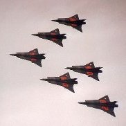 I am going to build a MiG-17F as a fighter bomber as used by Egypt in the war of attrition against Israel form the 6 days war of 67 up to the 1973 war to reclaim the Sinai peninsula. good in interesting reading from the arab/ not so well known point of view: Arab MiGs vol. 1-5 from Harpia publishing first dilema: which camouflage scheme to do? Egypt started to camouflage its aircraft right after the 67 war for good reasons. in the beginning quite crudely with light blue/ light grey undersides and sand/green/brown upper sides. hardly all aircrasft seem to be different. Later the famous nile valley scheme started to appear... to make matters more complicated, up to 1972? the roundels of the UARAF (United Arab Republic Air Force) Then the 2 stars of the roundels deleted and the flag usually carried on the tail received the so called Eagle of Saladin... I have decals for those... or could search for the older ones on other sheets. Here is what I have for now: kit with some necessary accessories and the kit's decals. looks good so far... fuselage with deep panel lines but quite nice shape: and the all important ordnance for a egyptian aircraft: unguided 76mm sakr rockets only available in the SMER kit additionally fuselage bomb pylons and bombs (to be replaced I think with aerobonus or similar) as well as 57 mm rocket pods. I bought more sheets than necessary... Hi Decal upper left, ILIAD upper right, SMER low: looking at the Eagle of Saladin in detail though: the kit decal look more childish, don't they? Hi Decals chose to do a very different eagle with a black outline, whereas Iliad design did a sheet for the Mig-15UTI with a red / gold outlined eagle.(apart from that, it is to be used for an aircraft of the 6 days war of 67....) so, which ones to use? or should I ditch them all and use the UARAF 2 stars and go for an "early" war of attrition?