
Search the Community
Showing results for tags 'Hobby Boss'.
-
 Next Hobby Boss Corsair kit will be a 1/48th Chance Vought F4U-1 Corsair early version - ref.80381. Release is announced for late August 2015. So should be available in the best hobbyshops in September-October. Source: http://www.hobbyboss.com/index.php?g=home&m=product&a=show&id=1125 Box art V.P.
 -
Hi All Started yesterday, Trailer first as I think a bit more leeway for poor fitting parts, get a feel for assembly for the Scammell itself, so far so good, gooseneck a bit of a tight fit to get the deck plate in, might not take too long, as the whole thing is just Green all over. Cheers All any tips on this would be appreciated if you have done one Mark
- 183 replies
-
- 15
-

-
- Scammell
- Hobby Boss
- (and 1 more)
-
Hello everyone, I have decided that I will start the new year 2024 with a chinese submarine: a Golf type 031: . . . . Very difficult for me to find the "right blue"... . . Chris
-
US T34 Heavy Tank (84513) 1:35 Hobby Boss via Creative Models Ltd Toward the end of WWII, when Allied tanks were encountering German heavy tanks such as the King Tiger and Jagdtiger, the American military put projects in motion that would be capable of matching them and dealing with German heavy armour (or Soviet for that matter), whilst remaining safe thanks to their own thick frontal and side armour. The designs were designated T29 and T30, both of which were almost identical save for the guns mounted in their turrets, sporting 105mm and 155mm main guns respectively. A further development, possibly inspired by the Nazis using their 88mm anti-aircraft gun in heavy tanks, was to see the high velocity 120mm M1 Anti-Aircraft gun reconfigured into an adapted turret. The gun could fire on aircraft up to 60,000ft, and consequently its armour penetrating power was devastating, far outstripping the other two guns that suffered from lighter-weight shells and with slower muzzle velocity respectively. It took until 1947 for the prototypes to be delivered to the proving ground in the US, and to balance the enormous barrel a sizeable chunk of armour was fitted on the bustle of the turret, possibly 99% redundant, but useful if the crew were caught napping. At a startling sixty-five tons, it was a weighty beast, and the US Army felt that it would be difficult to find a use for it thinking its weight could cause problems with bogging down on softer ground, and crossing bridges, in much the same manner that the Germans experienced with their heavy tanks during WWII. There was also an issue with fumes from the gun entering the turret, which was fixed by using an aspirator, but this came too late, and no production orders were made, the prototypes going into storage, and eventually finding their way into museums. The work wasn’t a total waste however, as a year later a lightened version of the T34 was designated as the T43, and was to enter service later as the M103 Heavy Tank, by which time its weight had ballooned up to the same 65 tons that had doomed the T34, using the same M1 gun, which was re-designated as M58 due to changes that had been made to it in the interim, including higher barrel pressure and quick-change capability. The M103 served with US forces until retired in the mid-70s, by which time Main Battle Tank doctrine had rendered the Heavy Tank a historic dead-end of tank design. The Kit Unsurprisingly, this kit is based upon the 2016 tooling of the US T29 tank that the T34 was based on, in a case of modelling production mirroring history. It has since had new parts added to turn it into a later T29 variant, a T30 and now a T34. The kit arrives in a typical Hobby Boss top-opening box with a slight corrugated surface to the lid, which has a dramatic painting of a T34 in the process of firing its main gun, with the muzzle-flash rebounding from the mantlet and turret. Inside the box is a cardboard divider glued to the tray to keep the large hull and turret parts from moving around the box and causing damage, plus most of the sprues are individually bagged, with additional foam strapping taped around various areas of the sprues and the front of the upper hull to further protect them during shipping and storage. There are ten sprues, two hull parts and the upper turret in grey styrene, eight sprues of track-links in brown styrene, two small frets of Photo-Etch (PE) brass, and a tiny decal sheet. The package is completed by the black & white instruction booklet that has a glossy, full-colour painting and markings sheet loosely inserted between the pages. Detail is good, and includes weld-beads, sand-casting and rolled-steel armour textures, plus individual track links and PE grab-handles/tie-downs for the sides of the many stowage boxes on the hull deck. Construction begins with preparing the lower hull for its road wheels by adding bump-stops, swing-arms and other suspension parts to the sides of the hull, including the idler and drive axles, with some wheel stations having additional dampers moulded-in to improve the ride for the crew. Massive final-drive housings are inserted into gaps in the rear bulkhead, along with a pair of hinged armoured panels, first fitting the seven paired idler wheels all along the upper run of each track, then building paired road wheels with a loose washer trapped between them, doing the same with the four-part drive sprockets, all of which can be carefully glued to the axles with the hope that they will remain mobile once the glue has cured, which might work, or might not, depending on how dainty you are with the glue. Each track run consists of 113 links, which are joined together by fitting the figure-eight pivots to the track pins, the outer edge having additional plates to widen the track that spreads ground pressure. A jig is included to assist you with production, and you’ll be pleased to hear that there are no ejector-pin marks on the inner faces of the tracks. Each of the track links has three sprue gates, while the pivots have just one each, all of which are sensibly placed to minimise clean-up, so whilst it will take some time to create the tracks, it shouldn’t drive you crazy in the process. With the lower hull looking good, attention turns to the upper hull where all the detail is. The upper deck is started by building two banks of stowage boxes around the base of the turret, which have separate lids, rails with eyes, and eight PE handles running along the outer sides. These assemblies are installed either side of the turret aperture, adding various small parts, including headlights, side-facing vision slots for the front crew, and a pair of two-part exhausts that mount at the rear of both fenders. A short run of track is bracketed to the glacis opposite the bow machine gun housing, and a few pioneer tool are fitted onto the fenders. On the engine deck, six louvred panels are inserted into holes, fixing a C-shaped exhaust pipe to the backs of the mufflers on the fenders, with an armoured cover protecting the straight central section. More pioneer tools are glued to the fenders, and these are joined by more PE handles along the edges, with cages mounted over the headlamps and the bow gun made from three parts including the barrel, sliding into the armoured shroud moulded into the glacis. The front crew hatches have rotating 360° vision blocks inserted into holes in the surfaces, then they are fitted into the hull, adding a grab-handle next to each one for egress purposes. At the rear, a small section of bulkhead is inserted into the remaining space, adding rear lights and other small parts once installed. The turret of the T34 is as large as some early WWII tanks, and is built from upper and lower halves, with a seam running along the side of the deep bustle, along the swage-line where the vertical side sweeps underneath. A machine gun is flex-fitted in a pintle-mount, adding twin grips, an ammo box made from three parts, and a two-part post into which the mount slides. The mantlet is also prepared from two layers of styrene, adding caps over the pivot pins so the gun can elevate, plus a pair of lifting eyes on the upper surface, making the commander’s cupola with a separate hatch, then fitting this and the mantlet to the turret, which has some very nice texture moulded-in, including weld-beads and casting roughness. The bustle receives an armoured panel to balance the barrel weight, inserting four parts into holes in the lower edge, plus brackets around the bustle sides, a shell-ejection port on the right side, stowage basket on the same side, a pair of aerial bases at the rear of the bustle, and the other two hatches either side of the keel that is moulded into the roof of the turret. The machine gun fits in front of the left hatch, and behind the commander’s cupola, a fairing sweeps around the side of the deck. The last parts for the turret include a choice of two styles of barrel, both of which are made from two halves that are split vertically, inserting your choice into the mantlet with a circular PE washer trapped between them. The turret locks in place on the hull by its bayonet lugs, and you have a choice of finishing the build with the travel lock in the stowed position flat against the engine deck, or vertically, supporting the barrel of the turret, which must be turned to the rear. Markings There is just one option on the decal sheet, and four white decals on the front fenders and the rear bulkhead, denoting T34 and 1949 on opposite sides. You might have already guessed that it’s a green tank, so pat yourself on the back if you did. Hobby Boss decals can be a little scant, but that’s what’s needed for this prototype, and as there is no registration to worry about, they’re perfect for the job in hand. Conclusion The T34, not to be confused with the Soviet T-34, was a monster of a tank, and it’s the first thing that hits you on opening the box. Detail is good, especially the textures moulded into the surface, resulting in a good-looking model that can be a canvas for your weathering techniques. Highly recommended. Review sample courtesy of
-
Hi, It's the last submarine I built:, HMS Astute (Hobby Boss): . . . . . . The sea made of resin... Chris
-
Hobby Boss is to release a new tool 1/48th Lockheed U-2R Dragon Lady kit in 2015/2016 - ref.81740 Source: http://www.britmodeller.com/forums/index.php?/topic/234972796-hobbyboss-148-for-2015/?p=1828290 V.P.
- 86 replies
-
- 1
-
-
- Hobby Boss
- U-2
- (and 1 more)
-
 #2/2024 One of my dad´s more rare excursions in the modern jet world. IMO still the most bada$$ ground attacker and CAS aircraft. As I´ve read it is declared dead once again in a few years....let´s see. Hobby Boss kit, mostly oob. HB did the same as Italeri and used their A-10A kit and added some things. But like Italeri also HB did miss some. For example the wing tip detail, found a solution by using 3D decals from Quinta Studio. On the original aircraft all is yellow, but kept the decals grey to keep the nice detail. The kit seat comes with shoulder belts but no lap belts, added them from the sparesbox. Ailerons and flaps can be positioned as you like, kept them in neutral position. Also the gun bay can be displayed open if you like. The racks come without "clamps". There would be aftermarket PE ones from Eduard but this is a bending nightmare for sure . Kept the pins on the racks, so they somehow look like the "clamps" from a distance. Painted with a selfmixed tone. Looking at the original aircraft, depending on the light it sometimes looks more green, then more olive. One little decal detail HB missed, the "O" of Norris includes a front view of the gatling. Build thread here https://www.britmodeller.com/forums/index.php?/topic/235132035-centennial-brrrrt148-fairchild-republic-a-10c-thunderbolt-ii-104th-fs-fightin´-o´s-maryland-ang/#comment-4806011 For the centennial anniversary of the Maryland ANG in 2021, one of their A-10C received a special livery. Later on, some green painted areas on the belly and underwings have been washed off again. DSC_0001 by grimreaper110, auf Flickr DSC_0002 by grimreaper110, auf Flickr DSC_0003 by grimreaper110, auf Flickr DSC_0004 by grimreaper110, auf Flickr DSC_0005 by grimreaper110, auf Flickr DSC_0006 by grimreaper110, auf Flickr DSC_0007 by grimreaper110, auf Flickr DSC_0008 by grimreaper110, auf Flickr DSC_0009 by grimreaper110, auf Flickr DSC_0010 by grimreaper110, auf Flickr DSC_0030 by grimreaper110, auf Flickr DSC_0031 by grimreaper110, auf Flickr DSC_0013 by grimreaper110, auf Flickr DSC_0032 by grimreaper110, auf Flickr DSC_0015 by grimreaper110, auf Flickr DSC_0033 by grimreaper110, auf Flickr DSC_0017 by grimreaper110, auf Flickr DSC_0018 by grimreaper110, auf Flickr DSC_0019 by grimreaper110, auf Flickr DSC_0020 by grimreaper110, auf Flickr DSC_0021 by grimreaper110, auf Flickr DSC_0022 by grimreaper110, auf Flickr DSC_0029 by grimreaper110, auf Flickr DSC_0001 by grimreaper110, auf Flickr DSC_0024 by grimreaper110, auf Flickr DSC_0001 by grimreaper110, auf Flickr DSC_0001 by grimreaper110, auf Flickr
 -
After the recently finished A-7E, my dad starts the next modern subject. DSC_0001 by grimreaper110, auf Flickr DSC_0002 by grimreaper110, auf Flickr
-
USAF XM706E2 (84536) 1:35 Hobby Boss via Creative Models Ltd The Commando series of light amphibious armoured cars was developed by Cadillac Gage in the US and was designated the M706. It was developed specifically for the Military Police and convoy escort in Vietnam, Its high ground clearance and waterproofing being suitable for the terrain being encountered. It was one of the first vehicles the US had which combined the roles of the APC and a conventional armoured car, carrying upto 10 troops in the back. The design would spawn a whole range of vehicles some with turrets carrying up to 90mm guns. The XM706E2, was supplied to the U.S. Air Force primarily for base protection purposes, but was also used for post strike reconnaissance and EOD roles. The open top lending itself to a variety of weapons including 50 cal, & 7.62mm machine guns, and in some case 40mm grenade launchers, though they were most seen with the duel machines guns. Not many of these vehicles were kept after the Vietnam war, but the USAF did retain some which served as late as the 1980s in Korea and the Philippines. Though by this time they were becoming very hard to keep operational. The vehicle would be replaced in various roles by the M1117 made by Textron who by this time had merged with Cadillac Gage. The Kit Hobby boss have done a variety of kits based on the same chassis. The kits are well engineered and build up with no problems at all as this reviewer has built one of them before. The kit arrives on 6 sprues of grey plastic, a clear sprue, upper & lower hull castings, a sheet of PE, I small sheet of masks, a small length of chain, and a small sheet of decals. All of the parts are well moulded with no defects. Construction starts with the interior, this is not massively detailed but there is enough in there to make it busy. The centre transmission tunnel goes in followed by some seats and the drivers controls, at the rear the engine compartment is boxed in. For the upper hull a series of holes need to be made and some internal equipment installed. The two main hull parts can then be joined, the lower hull actually slots into the upper one. Flipping the vehicle upside down all the suspension, steering, and drive components plus the axles are installed. Take care here as the front and rear springs look the same but are not (ask me how I know this!). To the rear hull a toll rack is added complete with individual tools. The wheels can then be made up and fitted onto the axles. Moving back to the top side the rear jerrican stowage is added along with various hatches, grab handles and the armoured windows. The exhaust grill is added to the rear also. Headlight guards and mirrors are added to the front. The main hatch for the vehicle is now made up. This can either be open or closed up depending on how you stow the covers. PE mounts now need to be made up the for machine guns. A 50cal and M60 are both included in the kit to mount here. Markings A small decal sheet gives markings for one camo vehicle and one overall green vehicle. No other information is given. Conclusion This is a great kit from Hobby Boss of a little seen vehicle, the kit is first rate and builds up easily into a good looking vehcile. Highly recommended. Review sample courtesy of
-
U-2R ‘Dragon Lady’ Senior Span (81740) 1:48 Hobby Boss via Creative Models Ltd Back in the 1950s, extreme high-altitude anti-aircraft missiles weren’t yet available, and aircraft could over-fly foreign nations with a degree of impunity, as long as they could stay high enough to keep out of range of enemy fighters and less capable missile batteries. Lockheed’s Skunk Works were tasked with creating a new aircraft on reasonably short notice that could fly higher than any previous aircraft or missile, virtually on the edge of space, to accomplish the task of gathering intelligence on America’s Cold War enemies, predominantly over-flying the Soviet Union. They took the fuselage of the new F-104 Starfighter that was then in development, adding massively extended wings more suitable to a glider, and shortening the fuselage, leaving sufficient space to carry high-definition optics and/or electronic intelligence gathering equipment. Developed in secret using black project money from the CIA, the airframes were developed in close proximity to the engineering staff, embedding them in the factory to quickly resolve any issues that came up, which resulted in the initial order coming in on time and under budget. New high-altitude fuel had to be developed, and the custom optics were designed specifically for use in the aircraft, which garnered the designation U-2, the U standing for Utility, to confuse anyone hearing about it, thus delaying its discovery a little longer. Once flights over the USSR had begun, it was discovered that the Soviets were regularly tracking the aircraft, which led to a project to reduce the type’s radar return, which was initially unsuccessful, but later was revisited by covering the skin in a Radar Absorbent Material (RAM) that was a matt black colour on application. There have been many upgrades and alterations to the type since it was initially fielded, leading to an aircraft that looks somewhat like the original, but is hugely different in terms of capabilities, especially when it comes to intelligence gathering. They still jettison their wing-mounted stabiliser legs on take-off however, and are stalked on landing by a muscle car to improve the pilot’s situational awareness from his cramped cockpit, which is worsened by the pilots having to wear a space suit due to the altitudes involved that would have a fatal effect on anyone flying whilst wearing a standard flight suit. The largest change other than building two-seat airframes for complex tasks and training of the elite pilots was the U-2R in 1967, which increased the size of the airframe by around 30% and introduced the wing ‘Superpod canoes’ that could be filled with intelligence gathering equipment and gave the aircraft a greater range by the enlargement of the fuel tanks. Despite the age of the basic premise and the march of technology, the U-2 has persisted attempts to retire it, even surviving the introduction of the un-manned Global Hawk, which is capable of many of the same tasks with extended loiter times due to the pilots being ground-based. NASA use a few U-2s, redesignated as ER-2s, which are used for high-altitude civilian research, painted white with the blue NASA cheatline as no-one is likely to want to shoot them down. The Kit This is a new tooling from Hobby Boss that was released late in 2023 and has only recently arrived this far from China, with another boxing depicting the U-2S expected soon(ish). The kit arrives in a top-opening box with a painting of the aircraft flying high, which is what it does best, with the stars visible in an inky black sky. Inside the box are seven sprues in grey styrene, a clear sprue, Photo-Etch (PE) sheet, decal sheet, instruction booklet, plus a colour profile sheet in A4, printed on both sides. Detail is excellent throughout, and incorporates some intelligent use of slide-moulding, particularly to create double-wall, single part intake trunks with detail on the interior and exterior. There are also a ton of aerials, antennae, a dorsal pod, and optional flat-spotted forward areas to the Superpod canoes under the wings. There is also plenty of detail in the cockpit, gear bays, and even a pair of detachable wing support wheels on their banana-shaped struts, plus air-brakes that can be fitted in the deployed position with a suitably well-detailed bay behind each of them. Construction begins with the two long fuselage halves, drilling out several holes in the top and bottom, and inserting the air-brake bay parts toward the aft end of the parts. Attention then turns to the cockpit, starting with the ejection seat, which is made from seven styrene parts plus four-point PE belts, which is installed in the detailed cockpit tub along with a two-part control yoke, fitting a bulkhead to the rear, and the instrument panel in front of the pilot, with a decal to depict the dials. Two side wall inserts are then fixed to the top of the consoles to finish the tub, moving on to the rear gear bay, building it from individual wall and roof parts, locating the gear strut between the side walls, and adding small diameter wide tyres to each end of the cross-axles. The exhaust is a simple tube made from two halves, and it is capped by a representation of the rear face of the engine after painting everything a suitable shade of burned metal. The front gear bay is moulded in excellent detail, showing the shape of the merging intake trunks within, to which the front strut and its retraction jacks are fitted, adding another pair of larger wheels to the stub-axle ends, painting both bays a grubby white. The merging intake trunks are made in two stages that are joined together to create a Y-shape, which is blocked at the rear by a part that represents the front of the engine, gluing it to the roof of the front gear bay, then fitting the cockpit, both wheel bays and the exhaust between the two fuselage halves and gluing them together. A forest of antennas is dotted around the underside, adding sideways opening front gear bay doors, a tail-bumper, and the actuators for the air-brakes into the bays near the rear. Yet more antennae are fitted along the belly, a sensor dome is mounted in front of the front gear bay, and the rear bay doors along with the air-brake panels are installed, flipping the model over onto its wheels to fit the instrument coaming to the cockpit, plus another antenna and light to the spine. The canopy is moulded in two parts, fitting a small exterior rear-view mirror on the port side of the windscreen, and PE interior rear-view mirrors to the canopy, gluing both into position, the canopy hinging to the port side if you plan to pose it open. The two intakes are an impressive piece of slide-moulding, having inner and outer surfaces provided as one part, with a hollow interior that reduces the likelihood of sink marks, whilst providing plenty of detail, each one gluing into the openings behind the cockpit. There is a slight seam around the intake lips that is easily removed, but the detail is well worth those few seconds of effort. The dorsal pod is made from two halves with a small raised blister on the pylon added to both sides, fixing it to the spine over the wing roots on pins, while the tail fin is built from two halves plus a single part for the rudder, which has a corrugated surface that is a little too deeply defined. Check your references and either fill the depressions, or sand back the raised portions as you see fit, although several coats of primer and some light sanding of the high spots might be better to retain the original thickness of the part. This also applies to the ailerons and other flying surfaces, so you might as well do them all at once, unless you’re upset by this minor issue. Each wing is made from top and bottom half, adding the majority of the Superpod body to the underside, with the top half of the tail cone a separate part, and the forward section that uses either two halves to create a cylindrical section with tapering nose cone, or by using different parts to create the nose cones with a flat-spot on the outer face, both styles having an optional L-shaped antenna installed on the top. The flying surfaces along the trailing edge are all separate, and are glued to the rear of the wing, with the possibility of deflecting them if you wish. Note that the black RAM isn’t painted under the extended flaps, so take care to check your references to help you paint this area correctly. A spoiler is also fixed to the upper wing around mid-span, near the jettisonable stabilising gear legs that are made from curved struts with a wheel glued to each side of the bottom end. These locate in a socket under the trailing edge of the wings, and of course the same process is carried out in mirror-image for the other wing. The wings are glued to the fuselage sides on three separate slots, and here it will become obvious that they have been moulded with a slight sag, which is correct for wings of this aircraft, so don’t be tempted to correct this. The two-part elevator fins have separate flying surfaces, and these fit to the fairing under the fin using a relatively small tab and slot, taking care to achieve the correct dihedral by checking your references. There are several nose modules used in U-2 missions, and this boxing includes a simple more aerodynamic nose that is made from two halves, plus a single cone tip, with two PE probes fitted to small depressions in the rear edge of the nose. It is glued in place to complete the build phase of the model. Markings Any U-2 after the early days is painted in black RAM, with very few markings, unless it’s one of the civilian airframes. There are three options included on the sheet, predominantly stencilled in red, and most of the decals are applied to the tail fin. From the box you can build one of the following: Hobby Boss decals and the decaling instructions can be a weak point of their products at times, and they are generally printed anonymously in China. This sheet is printed in this manner, but is suitable for purpose, particularly as the majority of decals are printed in red. Registration where it occurs is good, as is colour density and sharpness, with a clear backed decal depicting the dials and switch-gear for the instrument panel. Conclusion The moulding and detail included in the kit is excellent, and other than the excessive corrugated texture on some of the control surfaces, there is little immediately visible to grouch about, although some are still trying. Other than making sure you have enough space in your cabinet to accommodate the enormous wingspan of the Dragon Lady, there’s no reason not to have one. Very highly recommended. Review sample courtesy of
-
Bergepanzer BPz3A1 Buffalo ARV (84565) 1:35 Hobby Boss via Creative Models Ltd The Büffel as it is known as in its native Germany, is an Armoured Recovery Vehicle based upon the chassis and lower hull of the well-liked Leopard 2E Main Battle Tank, which itself is a variant of the 2A6. Most of the lower hull is identical or similar to its progenitor, but the turret is missing, replaced by a casemate and crane, a winch and a bulldozer blade that allows it to retrieve damaged or immobilised tanks from the battlefield even if the fighting is still ongoing thanks to its armour. It is also equipped with an MG3 machine gun for self-defence purposes, a set of smoke grenade launchers to hide itself and its charge from those that wish it harm. It is powered by a large 12-cylinder diesel engine from MTU Friedrichshafen, a division of Rolls-Royce, that outputs almost 1,500bhp that allows it to travel at good speed across all sorts of terrain, but also to pull its immobilised compatriots, whether they were retrieving Leopards or PzH2000 SPGs, or anything up to a similar tonnage. The BPz3 was a joint project between Rheinmetall Landsysteme of Germany who produced an initial 75 for the Bundeswehr and a further 25 for the Netherlands, where its name lost its umlaut over the U in translation. It was also sold to other countries including Canada where it is known as the L2-ARV, and Spain where it is known as the Leopard 2ER Búfalo, with Switzerland a surprisingly large 25 export, and Sweden taking a number on charge after adapting them to their specific needs to improve armour and customise their electronic systems. For service in Afghanistan, the German vehicles and some Canadian machines were upgraded with new high quality vision systems by Karl Zeiss for the drivers that would give them 24/7 visibility, no matter what the conditions. The crane is electrically driven, and can operate independent of the power-pack, so even the unusual sight of a Buffalo replacing its own broken engine isn’t outside the bounds of possibility, presuming they have enough electrical charge in the vehicle. At time of writing, the type is in the middle of another extensive upgrade programme to give it more capability on the interconnected battlefield. The Bpz3A1 is up-armoured to work under enemy fire, and included the addition of mine protection equipment, and slat armour that is intended to reduce the effectiveness of shaped charge weapons in key areas. The MG has been changed to a remote mount, and the driver’s vision is enhanced by a thermal imager and low-light TV system that are combined as a single picture in front of the driver, improving their situational awareness. The Kit This is a partial retool of a retool of the 2015 release from Hobby Boss, adding yet more new parts to depict the differences between the early Buffalo and the improved variant that is depicted here. The kit arrives in a typically sturdy top-opening box with a painting of a Buffalo at work on another tank, and inside are fourteen sprues and two hull halves in sand-coloured styrene, a small sprue in black, a clear sprue, two trees of poly-caps, a length of braided wire, two Photo-Etch (PE) brass sheets of parts, two flexible black lengths of track, decal sheet and black and white instruction booklet that has the colour painting guide sheet inserted between the centre pages. Detail is good throughout, as we’ve come to expect from Hobby Boss’s armour models for the most part, although there is some thought that the hull is around 4mm narrower than it should be, but that’s a question for your micrometre, not mine. Construction begins with the lower hull, which has the suspension and return roller details added after cutting small sections from some suspension units, while the road wheels are prepared, consisting of fourteen pairs of main wheels, two drive sprockets and two idler wheels, all of which have a poly-cap sandwiched between the two wheels. Once the swingarms with stub-axles plus return rollers are glued in place, the road wheels can be pushed into place for removal during painting if required, thanks to the friction-fit of the flexible polythene sleeves. Quickly, the bulldozer blade is built from large, bulky parts, adding supports and pivots, plus an oversized towing eye at the front of the blade. It is joined to the hull by a pair of large pins that you should leave unglued if you wish to move or remove it later. The track runs are of the “rubber-band” style, but have good detail throughout, and you are advised that they will accept standard plastic glue and paints during construction, however a test with Tamiya Extra Thin glue reveals that this isn’t the case, so test your preferred glue on the short length of sprue at one end of the tracks before proceeding. There is an overlap of two links per run, and once the glue is dry they are slipped over the running gear so that attention can turn to the highly detailed crew interior that is included. The interior is begun by taking a floor panel with a lip around most of the edge, and detailing it with three crew stations, their equipment and comfortable-looking seats. The completed lower half (there is more to come) is glued into the bottom of the hull along with an insert against the lower glacis plate, and at the same time the rear bulkhead with towing eyes and shackles are put in place along with the convoy-light shield that has a PE lighting bracket over it. The next stage of the interior begins with the upper hull half, which first receives an insert over the front that has two holes in it, creating the roof of the casemate in which the crew sit, opening a few small slots in the front of the hull, and drilling out six holes in the short section of roof that is moulded into the upper hull part. A very detailed insert is made up into a four-sided assembly with a lot of equipment placed inside over the next five steps, including tools, some PE parts and stencil decals. That is glued into the casemate and backed up with a box and some brackets, then more equipment and wall panels are dotted around the left side of the casemate after being detailed in rather busy steps around the main diagrams. Similarly, the right side is built around a long insert with five steps that increase the level of detail substantially, and includes PE and styrene parts as well as some more decals for stencils and dials. The driver’s console with D-shaped steering wheel is inserted into the glacis plate, then the assembly is turned over to detail the exterior, first cutting right-angled notches in three of the six triangular supports at the rear of the casemate, using the accompanying diagrams to measure them before cutting. The upper hull’s rear is boxed in with a wide bulkhead that includes rear mudguards, adding another small box on the rear deck, removing a few tiny raised areas and filling depressions nearby. Front mud guards, a front hatch and two side crew hatches are installed with handles, adding an armoured cover over the new rear view vision block. The two hull halves are joined, and a gaggle of small parts are scattered around the engine deck and the casemate, then the side doors are shown being installed again – oops! This time the rear door is fitted with styrene and PE parts inside, while in the front of the engine deck, two PE strips are bent around a pair of raised cylinders on the deck surface. The driver’s almond-shaped hatch is given clear vision blocks before it is inserted into the hole, and at the rear bulkhead several detail parts are fitted. A frame is fitted over the two circular vents, adding three PE mesh sections to the rear, and fitting a foldable panel to the left side, plus more detail parts on the visible part of the deck. The next few steps are incredibly busy due to the upgrading of the type requiring many more parts, creating an L-shaped box that is covered in PE mesh before it is located on the rear right corner of the deck. The top hatch with remote MG3 machine gun station is first fitted with six vision blocks in the toroidal lip, making the hatch from three layers for installation along with another vision block, then adding two bracket-like armoured covers over the top, and fixing the five-part gun and its mount onto the rear edge of the cupola. This is mounted in the socket in the roof, then a huge stowage box is built from styrene parts and PE mesh, installing it on the rear deck over the mesh cover, and fixing smoke discharger packs around the left rear corner and on the back edge of the deck. A lifting brace is detailed with eyes and a large shackle at the top of its sloped upper edge, connecting it to the right side of the engine deck via a pair of pins that mate with supports at each end. Two spare wheels are made and mounted on bobbin-like fittings, attaching it to a shallow tray with brackets around the edge, inverting it and fitting a four-part sled over it and fixing it to the dwindling open area in the centre of the engine deck. A stack of stowage boxes that bear a resemblance to coolers are made with separate lids, mounting two of them on the left side of the engine deck, adding two appliqué armour panels over the glacis above the dozer blade. The main crane is built around a single three-sided jib, the hydraulic lift cylinder is mounted at one end within the three sided part, then closed over by fitting the fourth panel, with a V-shaped cut-out to allow the movement of it and its ram, which is attached to a two-part base and ram with the turntable beneath it, mating them by inserting the ram into the cylinder and positioning the pivot-points at the bottom of the jib with those on the base so that pins can be inserted without glue. Even the crane doesn’t escape the application of pioneer tools, with several items on one side and slat armour at the aft end on the other, plus more details and of course the block and tackle that performs the heavy lifting. The pulleys are assembled with the supplied wire linking them, so some care will be needed, gluing the outer parts and the lifting hook in position, then locating the top pulley into the end of the jib, securing it with a pin from each side, again without glue. Another two towing rods are built in a V-shape with eyes glued to the ends and located on the rear bulkhead by a pair of clamps. The side skirts of the original vehicle have been replaced by new boxy assemblies that are fitted over the forward wheel stations, and have narrow slat armour panels at the bottom, spaced away from the skirts by triangular brackets, using two or three depending on the length of the section. The left skirts have a sloped top-section, while the right are box-shaped, but have the same slat sections on the lower sides. The next two pages are again incredibly busy, adding dozens of additional slat armour panels above the skirts, around the deck and casemate roof, and behind the built-out skirts toward the rear. Additional smoke grenade launchers are mounted on stations in the front corners of the glacis, adding more equipment and towing eyes to the rear of the vehicle, and a pair of antennae on the casemate, one with a flasher unit at the top that should be painted clear orange and used only when the vehicle isn’t on active duty. The quantity of small parts requires concentration and careful study of the instruction steps, as they aren’t always totally obvious, and could easily be missed by anyone skimming the steps. Markings There are two options available from the sheet, one wearing a two-tone green/sand camouflage, the other in all over sand. There are further decals on the main jib that can be found on the instruction booklet, which you will want to refer to during painting. From the sheet you can build one of the following: As usual with Hobby Boss, there’s no information on the vehicle’s location, date or user, so a bit of Googling will be in order if you’d like to know a little more about your model. The decals are well-printed, in good register and sharpness, and are suitable to the task in hand. The instrument decals for the interior equipment with dials has a grey background, although much of the interior is painted white or NATO green. Here, Google is your friend. Conclusion It’s a well-detailed model of a low-profile, but extremely important vehicle in the Bundeswehr and other operators, with a lot of attention paid to the interior, as well as a huge level of detail to the exterior. You don’t get the engine, but that’s not a big deal, and could be a relief, given the already high part count. Highly recommended. Review sample courtesy of
-
Russian MiG-29K Fulcrum D (81786) 1:48 Hobby Boss via Creative Models Ltd The Mikoyan MiG-29, known in the West by its NATO reporting name 'Fulcrum' is an air superiority fighter designed and built in the Soviet Union in the 1980s. As with other comparable aircraft of that period, such as the Su-27, F-16, F-15 and Panavia Tornado, it was produced in significant numbers and is still in fairly widespread service with air arms around the world. The MiG-29 was developed as a lighter, cheaper aircraft compared to the Sukhoi Su-27 Flanker, an aircraft with which it is broadly comparable in terms of layout and design, if not size and weight. As with the Su-27, the engines are spaced widely apart, with the area between them being used to generate lift and improve manoeuvrability. The MiG-29 is powered by two Klimov RD-33 Turbofans, each of which generates over 18,000lb of thrust in reheat. As with many Soviet types, the aircraft is well suited for use on rough airstrips, particularly as the engine air intakes can be closed completely when on the ground, allowing air to be drawn through louvres on the upper surfaces of the wing roots avoiding FOD. Armament consists of a combination of Vympel R-27 medium-range air-to-air missiles and R-73 or R-60 short-range air-to-air missiles, as well as an integral GSh-30-1 30mm cannon in the port Leading Edge Root Extension (LERX). The aircraft can be used in a range of roles and can carry bombs and rockets in addition to more technologically advanced missiles. The MiG-29 has been widely exported and is still in widespread use with Russian, former Soviet and aligned nations, including several NATO member states such as Poland. Based upon the MiG-29M, the K was developed in the 1980s as an all-weather carrier-borne multi-role fighter that incorporates modern technologies that make it comparable in terms of generational capabilities as the Eurofighter, Saab Gripen and Dassault Rafale. After two prototypes were built and demonstrated, the Russian Navy didn’t make an order as they were already wedded to the Su-33, and it was an order by the Indian Air Force that saved the project as late as 2009, which the Indian Navy intended to fly from the former Soviet carrier they had bought. The initial order of a dozen airframes was followed by another of 29, plus training and simulation equipment, although a pre-delivery crash put the brakes on temporarily until it was revealed that the crash had predictably been caused by pilot error. Reliability issues of the engines dogged the fleet for a while, solved by India’s efforts that led to their satisfaction with their aircraft, although talk of replacing the fleet at one point was taken seriously by Western aircraft manufacturers. Russia’s Navy eventually decided that rather than build new Su-33s to replace those that were reaching retirement, they would take advantage of the open production lines of the MiG-29K in 2009, adding two dozen to the production schedule, which led to the Russian Navy holding a mixed inventory of MiG-29K and refurbished Su-33s as of 2016 when the last MiGs were delivered. A small number of MiG-29KUBR airframes were built with two cockpits under the same shaped canopy for training, with tandem controls for the student and instructor. The operational airframes were received in time to take part in Russian operations in Syria, losing one that failed to return to base after an operational sortie. The Kit This is a new tooling from Hobby Boss, and it arrives in a sturdy top-opening box with a painting of the subject on the front, and profiles of the decal options on one side. Inside the box is a cardboard divider to reduce movement of parts during shipping and storage, and most sprues are individually bagged, with delicate parts pre-wrapped in thin foam sheets, secured by tape. There are nine sprues, two fuselage halves and four exhaust nozzles in grey styrene, a long clear sprue in a bubble-wrap envelope, a fret of Photo-Etch (PE) brass backed by a piece of card, decal sheet, instruction booklet in black and white, plus a folded sheet of glossy A3 printed in colour with one decal option per side, and another A4 sheet for the painting and decaling of the weapons that are included in the box. Detail is good, with intelligent use of slide-moulding to create additional detail without increasing the part count, and a choice of exhaust nozzles in closed or open positions, with excellent detail moulded into both layers. Construction begins with the K-36D-3.5 ejection seat, which is made from thirteen styrene parts, plus four seatbelts and ejection actuator handle in PE. This is slotted into the front compartment of the cockpit tub, adding the instrument panel and control column, and applying six decals to the panel and side consoles. Additional parts are fitted along with the cockpit sidewalls in both compartments, fixing a rudder bar with two PE foot straps in the front of the cockpit, remembering that most of the rear tub will be covered by an insert later in the build, so don’t waste any time painting and weathering that area. The nose gear bay must be built next, as it will be trapped between the fuselage halves, and this is built up from four parts, with the nose gear leg made from a single strut with integral supports near the top, fitting the oleo and swing-arm to the bottom, plus a clear landing light and other small parts before you attach wheels on either end of the cross-axle, building them from two halves each. The cover for the rear cockpit is raised, and has a grille on the front, plus two small boxes added to the top surface, then the fuselage can be prepared, drilling out several flashed-over holes under the wings, and one on the roof of the space between the engines. The nose gear bay is inserted into its cut-out, adding a pair of extension cups to the main gear bays behind the moulded-in sections, then gluing the cockpit tub into the upper fuselage along with an insert in the nose for a refuelling probe, whilst cutting off and sanding back a bulge on the deck in front of the windscreen as per a nearby scrap diagram. The two fuselage halves are brought together, fixing the rear cockpit cover and a small spine insert, then building the HUD from a sloped styrene core with clear lens, PE supports for the two clear panels, and applying a decal to the lens before it is fitted in a recess in the cockpit coaming. Soviet/Russian fighters tend to have built-in FOD guards, which in this case are supplied as large mesh panels that fit into the front of the inner engine intake trunks, that have a cylindrical profile and are blocked at the inner end by an insert that has the front of the engine moulded-into it, inserting the completed assembly into the engine nacelles, painting the inner surface grey, then adding the roof of the trunks to the sloped forward edge. This is done twice of course, and the two finished assemblies are inserted into the underside of the fuselage after adding extra wall detail to the main gear bays that nestle into the outer sides of each nacelle. In preparation, two short cowling sections are fitted to the upper fuselage where the exhausts will later sit. The twin fins are each made from two halves plus rudder, but they are equipped with different sensor fits in the trailing edge of the tip, which is further accentuated by the probe and sensors added to the rear, whilst both share the same T-shaped aerial near the change of angle of the leading edges of the fins. There is a large tapered cylindrical fuel tank between the engine nacelles, and this is built from two halves that are capped at either end, the nose cone made from two halves to include the forward pylon mount. This and the fins are put to one side while other assemblies are built for the underside of the model. This begins with the landing gear, the main gear made from a thick strut with trailing retraction jack, captive bay door, and a two-part scissor link, which receives a two-part wheel with circumferential tread moulded-in, although you’ll have to take a sanding stick to them if you wish to depict the weight of the airframe on the tyres. The exhausts have a short two-part trunk as their starting point, with a double layer depicting the rear of the engine and the afterburner ring, then you have a choice of posing the exhaust petals opened or closed, using two different sets of parts to portray the inner and outer layers of the nozzles. The closed nozzles have their inner part inserted from within, while the opened nozzles have their inner layer slid in from the rear due to the angles of the respective parts, with the resulting detail worth the effort. Both sets of nozzles are glued to the rear of the trunking, and are slipped inside the rear of the fuselage, adding the main gear legs and a bay door actuator to each side, then fitting the chaff & flare boxes on the fairings each side of the exhaust trunking, a pylon under each of the inner wing panels moulded into the fuselage, gluing on leading edges slats, and finally the twin fins that are attached to the fairings to the sides of the engines on pegs for strength. Doors are added to the gear bays, flaperons and their actuator fairings to the rear of the wings, a gaggle of antennae under the nose, and a two-part arrestor hook is fixed between the rear of the engine nacelles, mounting the large central tank between them. The next step is to fit the hinges to the ends of the inner wing panels, which are only applicable if you intend to fold the wings for storage on or below deck. This removes the option for a model ready for, or in-flight, and there is no discussion of the straight-wing or in-flight option in the instruction booklet. It is however possible using the parts provided, and simply involves omitting the hinge parts, laying the hinge cover panel flat to the wing, and fitting the outer wing panel at the same angle as the inner. The outer wing panels are built from two halves, adding slats at the front and ailerons to the rear, plus the hinge cover, which for folded wings should be placed at an angle. It’s best to test fit this in situ to obtain the correct attitude for the various parts. Regardless of whether you choose to fold the wings or not, each tip has a small strake inserted in a slot on the upper surface. More probes and antenna are clustered around the nose along with the refuelling probe with its cover, adding a clear lens to the sensor under the windscreen, which is also fitted at this stage. An actuator for the main canopy is installed behind it, and further aft two jacks for the air-brake are glued in position, which might be best done whilst fitting the panel to ensure they all line up. The canopy has a separate styrene lower frame with a cross-brace, four PE latches on each side, and a pair of rear-view mirrors in the front frame, fitting to the rear of the cockpit opening on the afore-mentioned jack. The elevators/elevons are single parts that fit into plugs on the side of the fuselage, and a gun fairing is fixed in the leading edge of the port LERX with another pair of PE antennae, one on each side of the nose cone, which has a separate pitot probe mounted at the tip. Like many Hobby Boss kits, this boxing has a plethora of weapons to suspend from the various pylons under the fuselage and wings. The following are included: 2 x R-77 (AA-12 Adder) BVR A2A Missile 2 x R-73M (AA-11 Archer) Short Range A2A Missile 2 x MSP-418K active jammer pod 2 x PTB-1150 1,150L Fuel Tanks 2 x KH -29T (AS-14 Kedge-B) TV guided A2S Missile 2 x KH-31P (AS-17 Krypton) Anti-Radiation Cruise Missile 2 x KAB-500Kr TV-guided bomb 2 x KH-35 (AS-20 Kayak) Anti-Ship Cruise Missile The various missiles are moulded as two halves, have separate fins fore and aft, and clear seeker heads where appropriate, adding adapter rails as necessary. The KH-35s however have their aft section removed before they are built, fixing folded fins to the sides of the missile, with a scrap diagram showing how they should appear once completed. A diagram at the end of the instruction booklet shows where the various munitions and pods can be mounted, but check your references for real-world load-outs if you prefer. Markings There are two decal options on the sheet, one in Russian service, the other in Indian colours. From the box you can build one of the following: Blue 39, Russian Navy 672 Indian Navy The various weapons, tanks and pods have a great many stencils that can be applied, using a separate colour page to guide you, all of which adds realism to your model. Decals aren’t always Hobby Boss’s strong point, but these are of good quality with registration, sharpness and colour density that are suitable for the task at hand. They usually go down well, and there are plenty of stencils for the airframe and weapons to add detail to your model, including more detailed instrument panel decals than many other companies provide. Conclusion The MiG-29 is an attractive aircraft, and the Navalised K from Hobby Boss seems a competent representation of what is a niche variant that was only produced in small numbers, including lots of detail and a large quantity of weapons. Highly recommended. Review sample courtesy of
-
RMS Titanic (83420) 1:700 Hobby Boss via Creative Models Ltd There can’t be many people that haven’t heard of the appalling and unnecessary loss of life that happened when the Titanic’s maiden voyage route intersected with an iceberg, causing huge gaps down the ship’s side due to blown rivets, overwhelming the safety measures that led many to believe that she was unsinkable. At the end of the day on 14th April 1912 she hit that fateful iceberg and began taking on substantial quantities of water. The ship’s waterproof bulkheads only extended to a level below the main deck, and one-by-one they overflowed, causing the Titanic to settle lower and lower in the water. Less than three hours later she broke into two and slipped beneath the surface with many of the passengers still aboard, and many more forced to jump into the almost freezing water, where most died from hypothermia or drowning. Over 1,500 souls were lost that day thanks to the hubris of the designers and impatience of the supervising crew, but many lessons were learned from this tragedy that are still applicable today, and many lives have subsequently been saved as a result. The 1997 blockbuster release of the film The Titanic brought the story to the public consciousness again after the wreck had been found over 13 miles from her expected location some years earlier. She was found lying upright and in two major parts, both of which had hit the sea bed at a considerable speed, badly buckling the underside. She has since been thoroughly inspected, and some of the knowledge gleaned from those expeditions was incorporated into the fictionalised plot of the James Cameron helmed film, which itself has become part of modern vernacular, with phrases such as “paint me like one of your French girls” raising the occasional titter. The Kit This is a new tooling from Hobby Boss, and represents the Titanic on her fateful voyage, although we understand another boxing will be forthcoming soon that depicts her sister ship Olympic in Dazzle camouflage livery, as she appeared during WWI as HMT Olympic, performing troop ship duties. The kit arrives in a rectangular top-opening box with a painting of the Titanic on the front, and two cardboard dividers inside that keeps the various aspects of the kit separately. There are ten sprues in grey styrene, plus the hull and six deck parts of varying sizes, a black styrene stand, a small sheet of Photo-Etch (PE) brass, decal sheet and black & white instruction booklet with separate colour painting guide slipped inside the pages. It’s immediately evident that this kit is intended to be a more “serious” kit than the recent offering from another company that came with a basic lighting kit, as the higher number of parts and monotone grey styrene suggest. When you remove the sprues from their individual bags, the detail is very finely engraved, showing delicate planking to the decks, window frames, doors and other fixtures, found all around on the visible surfaces thanks to a substantial use of slide-moulds that improve the model without increasing the part count unduly. The inclusion of PE parts is welcome, however this is a small sheet, and doesn’t include railings or other fine fittings that would be outwith the scope of most kits, and would cause frustration and extra expense to many modellers, who would see it as unnecessary complexity. They’d be entitled to think so, but the aftermarket producers are able to assist if the urge takes you to super-detail your kit. Hopefully, the research that Hobby Boss have put in is as good as the detail present. Construction begins predictably with the hull, which has hundreds of portholes, fittings and the distinctive banding around the hull moulded into it, plus the tapered stern where the rudder and screws will be placed later. The initial deck part covers the majority of the top surface, leaving the stern and bow to be added later, turning the hull over to fit the port and starboard prop-shaft fairings into grooves in the underside, with three props, one in the centre, which was the only screw with strong rudder authority, making her slow to turn, and could well have contributed to the collision with the iceberg once it was eventually spotted by the lookouts, who weren’t issued with binoculars, amazingly. With the hull righted again, the bow and stern deck parts are installed, and various deck fittings are applied over the next several steps. The superstructure is built from two deck parts, adding sidewalls to the lower layer, and building up the ends to prepare for the next deck, and includes the bridge. Two more deck parts are placed on the raised guides, adding a few detail parts to the smaller section to cover a blank space that couldn’t be dealt with by sliding moulds. The gap between the two superstructure parts is filled by a pair of walls, adding more inserts around the forward area near the flying bridges so that the deck above can be laid on top, detailing the open areas with more deck furnishings. The smaller upper deck areas are each detailed with dozens of parts, including life boats, davits, and a PE compass platform, resulting in seven sub-assemblies that are also placed in situ with guidance from the raised shapes all around the promenade, which is then covered with dozens of benches. The ostensibly complete superstructure is mated with the hull, taking care to align the bridge with the bow end, which shouldn’t be hard thanks to the raised guides that are used to assist throughout. A small forest of deck cranes are mounted on turret-like bases at the bow and stern, adding a couple of PE doors to the sides of the hull near the stern, which are likely either particular to the titanic, or were left off the mould by mistake and added later. Who knows? The Titanic had four large oval funnels, one of which was fake and was used to vent the heat and fumes from the kitchen so that the First-Class passengers didn’t have to smell the cooking odours. The three active funnels are made from halves with nicely engraved and raised details, adding an inner ring near the top, and covering it over with a PE grille. Painting the interior of the funnel tops a deep black should prevent anyone seeing the shallow base, and while the exterior of the aft funnel is identical to the others, the insert has a tube projecting up the centre, plus a pair of holes should be drilled in the floor. The PE grille is also different, with a solid forward section setting it apart from the others. The completed funnels are installed on the decks with their raised oval base plates assisting with placement, and taking care to glue the correct aft funnel at the stern end. Dozens of davits for the life boats are arranged around the sides of the main upper deck, with a few having a different design, and these are pointed out in the instruction steps. The lifeboats are suspended from each pair on the deck, which is best done after the glue on the davits is totally cured, fitting the two masts as the final act. The foremast has a small crow’s nest for the lookouts and an angled jib, while the stern mast has a single level jib facing forward. Both masts will have copious rigging, but there are no diagrams showing where it should be fitted, however the box art should assist with this, as the Titanic is almost directly side-on to the viewer. Markings The Titanic didn’t last long after it embarked on its first and final voyage, floundering without completing a single crossing with huge loss of life. You can build her as she left Southampton below: Decals are printed by Hobby Boss’s usual printers, and are fit for purpose, although under magnification the blue seems very slightly out of register on our sample, but unless someone is very sharp-eyed, it probably won’t be noticed, especially if you don’t use the US flag that’s supplied. Conclusion This is a very nicely detailed kit of the Titanic, particularly at this relatively small scale, with deck, windows and portholes finely engraved. It’s not a gimmicky kit that lends itself to a quick build with lighting, it’s for the modeller that wishes to build a well-detailed model as a little part of maritime history, as an homage to those that lost their lives. Highly recommended. Review sample courtesy of
-
German Sd.Kfz.171 Pz.Kpfw. Panther Ausf.A (84830) 1:48 Hobby Boss via Creative Models Ltd The Panther was Germany's answer to the surprise appearance of the Russian T-34 after they finally reacted to the invasion that was Operation Barbarossa. Although the project had been in gestation some time before, they took some design cues from the T-34 in the shape of the sloped front and side armour, resulting in the Panther that was intended to fill the gap between the Panzer.IV and the (then) new Panzer VI Tiger. It was eventually supposed to replace both the Pz.IV and the earlier Pz.III that was really showing its age, but in reality it often fought alongside the Panzer IV. It was planned as a lighter, more manoeuvrable tank than the Tiger, and was fitted with a high velocity gun from the outset, which gave it enormous penetrating power that was only equalled later by the 17-pounder the British fitted to the American Sherman to make it into the more lethal Firefly. The sloped frontal armour gave it an increased effective armour thickness, but this was not so true of the side armour, which was comparatively weak, and this area became the preferred target of engaging allied tanks, especially in urban combat where this was a telling issue. Like most German WWII tanks it was filled with advanced engineering and therefore complex to produce, so suffered in terms of output volume, and this led to it being rushed into service with a long tick-list of issues still to resolve. Later production resolved most of these initial gremlins, but loses in the interim were high with many being abandoned after breakdown during combat. Confusingly, the Ausf.D was the first to enter production, with the Ausf.A following later in 1943, replacing attrition of the less reliable Ausf.Ds until they themselves were superseded by the Ausf.G, which became the final major variant with increased ammo storage, simplified design to ease production, and further improvements to reliability, although this was never fully cured with a high rate of attrition persisting due to mechanical issues, some of which resulted in catastrophic fires. The Kit There was a discussion thread within the last week here on Britmodeller about why 1:48 didn’t take off as a common scale for AFV modelling, and no-one could come up a definitive reason for it. A possible reason could be that not enough companies were willing to put their time and effort into creating new toolings, amongst others. Now we have this Panther from Hobby Boss to widen the range a little, and we suspect it won’t be the last from them. It is a new tooling, and arrives in a shallow top-opening box in the usual HB style, and inside it is divided up into two areas by a card insert. There are four sprues and three hull parts in tan styrene, a tree of translucent poly-caps, a small fret of Photo-Etch (PE) brass, a decal sheet, instruction booklet in black & white, plus an A4 sheet of glossy paper, printed in colour on both sides. Detail is good as we’d expect from Hobby Boss, and the inclusion of PE goes further in the quest for realism. Construction begins with the running gear, building up a pair of three-layered idler wheels, eight pairs of road wheels with poly-caps in the middle, suspension bump-stops, the final drive housing with two-part drive sprocket and a small wheel that helps prevent the tank from throwing a track. The rear bulkhead is detailed with a pair of exhausts linked by a cross-brace, a jack with separate handle, plus two stowage boxes with stiffening Xs moulded-in. The lower hull is fitted with armoured final drive surrounds, bump-stops, the drive sprockets, interleaved road wheels and idler wheels on both sides, finishing the lower hull by installing the rear bulkhead. The tracks are link-and-length, with long sections top and bottom, a short straight section on the diagonals, and individual links around the tightly curved ends to the runs. A scrap diagram shows the correct sag to the return run, and of course the task must be carried out on both sides of the vehicle. The top run will be mostly hidden by the side skirts, which are mounted under the sponsons on L-shaped brackets, finishing the front by adding the curved mud guards. Two towing eyes are mounted on the rear on the torch-cut ends of the hull sides, which are smooth and would benefit from adding the texture with a little liquid glue and a blade indented across the end. The upper hull is well-detailed, and should have two small holes drilled at the front of the deck, adding hatches for the front crew, racks filled with separate pioneer tools, and additional racks at the rear that hold spare track links. The large engine inspection hatch is prepared with lifting handles, the driver’s vision port is made from two parts and installed, adding a headlight to the side, and fitting track links to the racks at the rear, then covering the louvres on the engine deck with PE mesh to keep smaller debris such as grenades out of the engine bay. A two-part travel lock is mounted on the front of the hull using the two holes drilled earlier, and a tube for the barrel cleaning rods is locked into place on brackets on the left side of the hull. The turret is moulded with all but the rear face that has a circular hatch moulded into it, plus the roof. It is glued onto the lower turret part, and has a choice of two cupola types for the commander. One has a tapered cast body and vision blocks moulded-in, the other is layered from four parts and has an MG34 machine gun on a pintle mount at the front. The gunner’s hatch is a single part with a handle attached just in front on the corner, leaving just the main gun to build. This is made from the breech, which is not accurate because it won’t be seen, adding two poly-caps to the pivots, the mantlet to the front, and the single-part barrel with slide-moulded hollow muzzle slipped into the front, pushing the completed assembly back into the turret aperture to locate it. The final step involves joining the upper and lower hull halves, and adding the turret to the ring, then installing a pair of width indicator ‘lollipops’ to the front mud guards. Markings As is usual with Hobby Boss, the markings options don’t give any details of when and where the schemes were seen, but give colour codes in Mr Hobby, Acrysion, Vallejo, Model Master, Tamiya and Humbrol paint systems. From the box you can build one of the following: The sheet includes three rows of 0-9 digits plus a few spare zeroes and 741 codes for one of the decal options, plus two Balkenkruez crosses in case you wish to use them. All the numbers and crosses have a thin white outline, and they appear to be in good register under magnification. Conclusion If you’re looking for a crisply-moulded 1:48 Panther for your next project, this will make a good candidate, striking a balance between size and detail, without unnecessary oversimplification. It will however be a faster build than a 1:35 scale alternative, and take up a lot less space in the cabinet. Highly recommended. Review sample courtesy of
-
Hobby Boss is to rebox in late December 2016 the Tristar's 1/35th Fieseler Fi 156A-0/C-1 Storch kit - ref.80180 Source: http://www.hobbyboss.com/index.php?g=home&m=article&a=show&id=76 Box art Even the box art is the same Sources: https://www.scalemates.com/kits/105657-tristar-35034-fieseler-fi-156-a0-c1-storch http://www.tonyshop.fr/tristar-103/tristar-35034-fieseler-fi-156-a-0/c-1-storch-1/35-6060.html For kit reviews: http://www.cybermodeler.com/hobby/kits/tri/kit_tri_35034.shtml http://www.perthmilitarymodelling.com/reviews/vehicles/tristar/tri35034.html http://www.militarymodelling.com/news/article/fieseler-fi-156-c-3-trop-storch-in-1-35/7466 V.P.
- 9 replies
-
- 1
-
-
- Hobby Boss
- Storch
- (and 1 more)
-
While I was building my Me 262 2-seater I thought it would be a good time to build this kit that I have had for a few years, the Hobby Boss Me 262A-1a/U4. First a bit of history behind it: As the daylight bomber attacks on Germany intensified in 1944, attempts to bring down large numbers of American B-17 and B-24 bombers was getting more difficult. they were coming in ever larger formations of up to 800 aircraft and with over a 1,000 fighters for protection. Gorings first idea was to build more German bombers, he reasoned that if the Luftwaffe bombed the UK severely they would be too pre-occupied to carry on attacking Germany. This idea didn't go down well and it was pointed out that German industry was unable to produce sufficient aircraft to match the allies productivity even without the bombing of their aircraft industry. General Galland knew that his fighter pilots were being killed in ever greater numbers due to the defensive fire from the bombers and also their fighter escorts. As heavier weapons were fitted to the FW 190 and Bf 109 German defensive fighters to enable them to bring down the US bombers, this extra weight reduced their performance and they became easier targets for the US escort fighters. An idea to use ever larger calibre weapons that could destroy the attacking bombers with a single round from outside the range of their defensive fire was devised. Bf 110's with 37mm canon and then Me 410 aircraft with a 50mm canon were utilised, however results were inconclusive, these heavily armed twin engined fighters were easy prey for the more agile single engine US fighters and with such a long barrel, even a small deflection made the projectile miss it's target. Despite evidence that the 30mm weapons were downing the majority of US bomber losses an attempt to fit the 50mm canon to the jet powered Me 262 interceptor was attempted in 1945. The first Me 262 was converted from a standard fighter, to accommodate the large weapon the nose shape was enlarged and the nose wheel had to rotate flat with the underside of the nose on retraction. after evaluation this aircraft was issued to JV 44 and flown in combat on 16 April 1945, attacking a force of B-26 Marauders of the 9th AF it's canon jammed. No other flights were recorded and the aircraft was destroyed as US ground forces approached the base. Two other aircraft were being converted to carry a 50mm weapon, only one was completed and it was captured by US ground forces at Lechfeld airfield. It was marked up with US markings and then flown to France with the intention of being shipped back to the USA for testing. Unfortunately it crashed on landing, thus ending the saga of the 50mm armed Me 262's. Here is the Hobby Boss kit: As can be seen, it has not been started. These kits are good fitting but need a bit more work to assemble than the Tamiya kit, but HB made all the obscure versions so we are lucky for that. I have some extra bits to help make this kit, some Eduard resin wheels to replace the strange kit ones, a Master metal barrel with a nicely perforated brass muzzle break to replace the kit's solid plastic one. The kit provides a metal nose wheel bay to provide sufficient nose weight and it is correctly shaped so that the nose wheel could lay flat. Some Quinta 3D cockpit decals to perk up the instrument panel and side consoles. The kit markings are a bit mixed up, it shows the initial nose art applied by the US forces, "Wilma Jeanne", this was later changed to "Happy Hunter II" before its final fight to Cherbourg where it crashed on landing. It never carried either of these names with German markings just the alpha/numeric V083. I'm not sure yet how I will finish the aircraft, but if you want the nose art you have to source your own US star and bar decals. It will give me something to do while my other Me 262 build has it's sprue gloop hardening. Any questions or comments are always welcome.
- 23 replies
-
- 18
-
-
- Hobby Boss
- 1/48th
- (and 1 more)
-
In Autumn 1944 I./KG(J) received a Me 262B1 trainer jet, it was painted with a white lightning bolt from the windshield to the nose cone on both sides of he nose. There were two photos published in the Luftwaffe Im Focus magazine. I have the 1/48th Hobby Boss kit of the Me 262B-1a that has these markings. The kit is nicely detailed but the real thing had most of the panel lines and rivets were puttied and smoothed to maximise the speed that could be obtained from the Jumo jet engines. The wheels in the kit look a bit strange, the wheel rims are moulded smooth with the tyres and the sidewalls of the main tyres have a strange pattern marked on them so I will replace them with some resin ones from Eduard. There is a set of Montex masks for the canopy and also the national and other markings and some Quinta 3D decals to enhance the cockpit. I started off by adding some dissolved putty on the fuselage panel and rivet lines just like the real thing, while that dried I set to on the cockpit parts. There aren't too many parts, the side consoles and i/p had all the raised detail removed ready for the 3D decals, all other cockpit parts were added to the tub ready to get painted. I assembled the gun bay, since I will be having the gun bay panels closed so it seems pointless to add the 4 canon and belt chutes. The upper and lower wings parts were removed from the sprues and cleaned up, I'm looking at photos to see which panel/rivet lines I need to fill. In the lower photo you can see a second cockpit tub from a single seater, this is because I realised that HB have only made the cockpit of the nightfighter. I thought it was strange that there were no rudder pedals or control column in the back when the trainer version had full dual controls for the experienced pilot in the rear seat. The aerials are included in the kit so it is exactly the same moulding, just different decals and box art, but it means it's up to the builder to correctly modify the kit if they want to make the trainer version. So much for a quick, straight forward kit build. The aircraft that were built as nightfighters had no flight controls in the back, only the radar controls, but the main difference was the 600 litre fuel tank added behind the radar operator, this meant his seat was moved forward reducing the area of the rear cockpit. I've worked out how to correct this error, I need to cut off the short rear cockpit behind the pilots seat and add a spare single seat cockpit section with all the flight controls onto the front tub, with a bit of fettling this will make it right, then I just need to scribe a new step panel and fuel access panel to the left side of the fuselage under the rear canopy... simples! Any questions or comments always welcome.
-
Here’s my "VIRGINIA" I did just finished recently: . . . . . . Chris
-
I've put the finishing touches to this 1/32nd scale B-24 over the Bank Holiday weekend and took advantage of some spring sunshine to take some pictures of the completed model outside in natural light. I've been working on this on and off for a year or so, and it has been the ideal project to pick up and do a bit to as and when I felt like it. This model doesn't get the best press but I must say I thoroughly enjoyed every minute of it. You can spend a fortune on after-market improvements if you wish, but other than some seat belts, resin wheels and gun barrels, this is how it comes in the box. The interior is crammed with detail and took a long time to complete - excellent value for your money when you compare it to the price of the other 1/32nd 'heavies' on the market. Fit was excellent throughout and the only filler used was to deal with a small gap along the underside of the nose where, I believe, I hadn't got the interior aligned as perfectly as I could. The turrets, however, are a weak point of the kit. It's been well documented that the rear turret (and forward turret on the J-version) have a very visible seam right down the middle. Aftermarket replacements are currently sold out so instead I used the kit rear turret and painted the mating surfaces black before gluing and this has made the unsightly join a little less conspicuous. For some reason Hobby Boss put heavy framing on the upper turret which doesn't exist on any B-24 turret I've seen, so this was sanded off and the dome given a good polish so it now better represents the Martin turret fitted to this model of Liberator. I didn't want to risk putting the colossal amount of nose weight into this as I was using the kit's plastic landing gear (which is perfectly strong enough to cope with the weight of the 'un-weighted' model) so I made a tail strut as was so often put in place when B-24s are parked on the ground. The kit doesn't come with the most inspiring of schemes for an olive drab B-24, so I did a bit of research on 'Satan's Angels' and painted the model to represent this aircraft as it would have looked in the autumn of 1943 with the group insignia on the tail and the short-lived red surround to the stars and bars. This aircraft was actually written off in a landing accident at Lympne in Kent, when the nose wheel collapsed and it ended up in a ditch on 13th November of that year. I used Kits World national insignia as well as the Profimodeller stencil set. All in all a very enjoyable build, and if you want a large 1/32nd bomber that doesn't break the bank but still gives you plenty of detail, I thoroughly recommend this kit. All the best, Tom Consolidated B-24D Liberator, 'Satan's Angels' of the 328th Squadron of the 93rd Bomb Group, based at Hardwick, Suffolk, Autumn 1943.
- 28 replies
-
- 98
-
-

-
- Hobby Boss
- Liberator
- (and 1 more)
-
 Hi all, Trying something new with this tried and tested Hobby Boss kit of the tropicalised Spitfire Vb. This model is intended to complement the 1/32 Spitfire Vc I'm also planning to build over the winter! The box! Nice artwork of Wg Cdr Ian Gleed's clipped and cropped Vb with the Aboukir filter. My intention is to build it with an interchangeable nose section so I can swap out the exposed full engine nose for the streamlined covered version using magnets. Quite ambitious, but technically possible! I'll be building it as AB502, Ian Gleed's Vb of 244 Wing. All the best, Alan
- 84 replies
-
- 8
-
-
- 1/32
- Hobby Boss
- (and 1 more)
-
Sometimes I cheat on my Luftwaffe planes with USN a/c, although, an F4F was actually my first ever 1/48 scale kit. Last effort: the Revell Dauntless. Besides my fascination with carrier aviation, I also wanted to use this kit to try out weathering with oil paints. It came out, well, let's say allright - with much room for improvement. and it goes nicely with my collection so far, especially on the flight deck (and YES I am aware that the flight deck is Japanese, but I couldn't get my hands on the US version ) As always, thanks for looking Cheers here's my collection from the "dark" side https://photos.app.goo.gl/od4agvy1tebuSm7L8
-
Pz.Kpfw.VI Sd.Kfz.182 Tiger II Henschel 105mm (84559) 1:35 Hobby Boss via Creative Models Ltd The King Tiger needs little introduction to most armour aficionados, as it became one of WWII's truly iconic AFVs, even though it saw only limited action in the closing months of the war, and had serious flaws that were never fully resolved due to its short time in service before the factories and then the Reich were over-run. As with any new equipment, Hitler was insistent that he was involved and always wanted bigger (compensating much?), which resulted in a heavily armoured tank with a massively powerful gun, but weight problems that put undue strain on its engine and transmission, resulting in a high preventative maintenance burden and frequent breakdowns on the battlefield. It has been said that more King Tigers were lost by crews having to abandon and scuttle a broken-down vehicle during a fight than were knocked out in battle. The design was complex, and although the simpler later turret design was chosen over the alternative and more complicated early offering to ease construction, it still took far too much time and valuable resources to create one, especially when compared to the comparatively rustic T-34s that the Soviets were churning out in huge numbers. The initial turret design was more complex to produce, and can be identified by their curved sides to accommodate the commander’s cupola, which was difficult to produce as it demanded high levels of accuracy in shaping thick armour-grade steel. This is the turret we usually call the “Porsche Turret”. They were fitted to the first tanks off the production line, and as such the later simplified design that we call the “Henschel turret” should by rights be the "second production turret", as the initial turret design was a common element of both Porsche and Henschel designs. Upgrades were proposed to solve some of the more pressing issues with the type, which included a replacement fuel-injected engine that would add around 100hp to the power available, although a new gearbox and transmission unit was discarded due to negative experiences during testing. The main armament was also to be upgraded to a 105mm KwK L/68 unit, but the army had not yet accepted the design, so it would have been a risky upgrade. As it happened however, events conspired against the Nazis and the war ended before any significant improvements could be made to the already impressive capabilities of the Königstiger, which we interpret literally as King Tiger, but actually refers to the Bengal Tiger in German. It took bravery on the part of Allied tankers to tackle a King Tiger, as they had to get well inside the killing zone of the mighty 88mm gun in order to penetrate the frontal armour, and even the flanks weren't easy to breach, having 80mm of sloped armour on the hull and turret sides. The Allied tankers developed a technique whereby a squad of tanks would attack a KT from various directions, hoping that in the confusion one or more would be able to flank their target and get close enough to penetrate the side armour, while the others dodged incoming rounds from the devastating main gun. This task was made a little easier by the introduction of the ‘Jumbo’ Sherman with high velocity gun, and the Pershing heavy tank, although these were also only available in limited numbers before the war ended. The Kit This is a new boxing of the base kit from 2018 with additional parts to depict the larger gun, building on their well-detailed rendition of the behemoth. The kit arrives in a large top-opening box with a painting of the 105mm equipped KT that is presumably rolling through the debris of Berlin in a last-ditch attempt to stave off defeat. Whether any up-gunned KTs were taken from the testing ground into action we’ll probably never know for certain, although that doesn’t mean it didn’t happen. The fact that one of the decal options has a red primer covered turret certainly implies that the designers of the kit think they did, but I can’t remember seeing any evidence in my wanderings. Inside the box is a small divide to keep the sprues from moving about unnecessarily, and there are plenty of them to be kept still. There are fourteen sprues of grey styrene, ten in brown, a single clear sprue, a sheet of Photo-Etch (PE) in a small bag with the decal sheet and a card backing, the instruction booklet that is printed in black and white, and a single sheet of glossy A4 printed in colour that depicts the two markings options. Detail is very good, especially on the armoured areas of the tank, where there is a nicely restrained depiction of the texture common to rolled armour-grade steel of the era. The sand-cast texture on areas such as the exhaust armour and the mantlet is present, although it would probably benefit from being accentuated by stippling with liquid glue or Mr Surfacer and an old brush to ensure it doesn’t disappear under paint. Construction begins with the lower hull, adding the armour covers to the front of the final drive housings, then threading the swing-arms and torsion bars through the hull from both sides, followed by the road wheels, which must be applied in the correct order to achieve the interleaved effect. The four-part idler wheels and two-part drive sprockets with the final drive bell-housing incorporated are made up in a confusing flurry with arrows everywhere, then they too are installed along with long and short caps to the centres of the road wheel stacks. The tracks come next, and they’re an interesting part of the model as they have good detail, and with a little care can be made up to be workable. Each track run is handed, and every link is made from the main part that has the tread detail moulded-in, and has an insert added to the inner face, with another overhanging behind it un-glued. This then forms the insert for the next link, with another insert added to the rear, a process that continues until you have a run of 92 links per side. The main link has two sprue gates on the hinge-points, while the inserts each have two sprue gates on edges that are easily sliced away, so shouldn’t take long to prepare. There are also three tiny recessed ejector-pin marks on the exterior face, but with paint and a little bit of mud they probably won’t be noticed, so fill them if you’re inclined or hide them later. Attention shifts to the rear bulkhead, which is detailed with twin exhausts in armoured shrouds, adding two track tools, Notek convoy light and a large shackle between the exhausts, which is something I’ve not seen before. The bulkhead is slotted into the rear of the lower hull and has a pair of towing shackles clipped on with no glue, allowing gravity to do its work. The upper hull has the domed kugelblende armour fitted to the glacis from the outside, adding the pivot and socket from inside, and a clear periscope through a slot in the front deck. To fill the hole in the ball-mount, the machine gun is made up with sighting and grip mechanisms, plus a twin saddlebag magazine, and a domed cap on the left that allows the top of the gunner’s head to take some of the weight of the breech and assist with movement. The rear of the upper hull is open at this stage, with just two rails joining the front to the back, which will help support the engine deck insert when it is completed. Work starts on this by adding the large maintenance hatch in the centre with triple mushroom vents mounted on top, then detailing it with lifting hooks, more mushroom vents and hinge-covers, applying PE meshes over the grilles to prevent debris and grenades getting into the engine bay, followed by mounting it over the bay. The front hatches are usually moulded in an insert on King Tiger kits, but Hobby Boss have elected to mould it into the upper hull, having a small insert with a clear periscope in front of the driver’s hatch, fitting armoured covers over it and the other periscope that was installed earlier, plus simple hatches. The pioneer tools are installed all over the deck and side of the upper hull, the hand-tools having PE clasps, while the fully styrene towing cables with moulded-in barrel-cleaning rods are mounted on pegs on the sloped hull sides, surrounded by more pioneer tools with PE clasps. At the front, a cyclopean headlight is mounted on a central bracket on the glacis, with the wiring snaking away aft, adding some PE details for effect. The fenders are moulded as single lengths on each side, and these have been thinned at the edges to give a more realistic look. At first glance, the instructions seem to imply that adding the fenders should be done over the small rectangular PE mounting blocks, but a short text to the side states (using mostly part numbers) that you either fit the fenders or the mounting blocks. If you cut sections of the fenders out to depict lost portions, you can apply the blocks in the missing area, and depending on whether you think that the area behind the fenders would be left in primer, that gives some leeway for a little bit of fancy painting. In action, these fenders were often casualties of incautious or hurried manoeuvring, and were bent, mangled, or even torn from their mounts, as evidenced by many photos of the type. A pair of front mudguards of the later type are pushed onto rectangular holes at the front of the hull, adding separate sloped sides, and two more towing shackles are clipped over the torch-cut ends of the hull sides below. The texture of torch-cut armour isn’t replicated at the front or rear, so check your references and have a go at recreating that if you wish. It’s not too difficult, and can be achieved with a file or sharp blade. Speaking of the rear, simple sloped panel mudguards are fixed to the rear, with small PE eyelets added to the mounting point. Turret time! The turret build starts with some of the ancillaries, first of which is the commander’s cupola, which has seven vision blocks inserted into the two-part surround, with seven frames glued to the interior, plus six armoured covers and one that has a pin moulded into the top, attaching the three-part hatch with a long pin from below so that it can raise and turn to open, adding a PE backup sight to the front of one periscope. The mantlet shroud is next, which is specific to this variant, made from three interlinked cylinders of varying sizes and lengths, plus a PE part folded and glued on top of the widest section. The gunner’s hatch is a simpler radiused rectangular affair, having grab-handles inside and out, plus a locking wheel in the centre and a curved hinge-guide on the underside. The rear turret hatch is built from two layers that trap another part in between, then a pistol-port is inserted into the centre from both sides (I thought these were deleted on later production?), adding grab-handles and hinge-points, which are partly covered by either a styrene inner layer, or alternatively, a PE part that is bent to the curve shown next to it in the instructions. The outside also has a grab-handle fixed to the top edge. The larger 105mm barrel is particular to this variant, and is made from a full-length section that has the wider portion fleshed out by adding the other half of the cylinder to the hollow half, fitting a four-part muzzle brake to the dangerous end. With careful fitting and sanding of the mould seams, no-one will know it isn’t made from turned aluminium. As it’s an exterior kit, the turret interior is absent, the gun pivot made by fixing a short cylindrical socket to the two-part floor by a pair of trunnions, using no glue on the pegs if you want to pose the gun later, or just leave it mobile "for reasons". The upper turret is slide-moulded as a single part minus the front, adding two bent PE parts to the forward roof, positioning them with the aid of two scrap diagrams nearby. More detail is fitted to the roof in the shape of mushroom vents, a shell ejection port and some lifting eyes, then inserting the two-part mantlet in the open front from both sides. Surprisingly, there are detail parts inside the roof of the turret, carrying the external details inside, and adding a periscope and more details just in case humanity gains the ability to see round corners later in our species’ evolution. The gunner’s hatch, commander’s cupola and yet more details are installed over the following steps, including multiple cleats on which to hang spare track links, adding three to the rear and two to the front of the side armour. All the location points for these small parts are marked on the hull texture as very fine, almost invisible shapes to help you, which also extends to the strange blister-shapes that are applied to the top edges of the turret sides. I must find out what those are, as I’ve not seen them before. The spare track links have small portions removed because they are hung individually rather than as a run, showing where to cut in more scrap diagrams. The gun shroud slots over the tube projecting from the mantlet, and that accepts the rest of the barrel, adding the rear hatch at the same time. Incidentally, this was the only way the gun could be removed from the turret after completion of the real thing, which explains its presence and comparatively large size, as well as the fact that it can hinge almost flat against the deck. The completed turret drops into position on the hull, and as it doesn't have the usual bayonet fitting to hold it in place, you'll need to remember that if you ever turn it upside down. Markings There are two options on the profile sheet, and as usual Hobby Boss’s designers aren’t forthcoming with information on their veracity or otherwise, but as this particular variant wasn’t officially involved in combat, you can take them with as many pinches of salt as you wish, or just go your own way and paint it how you see fit. From the box you can build one of the following: Decals are printed in China, and have decent register etc., but as none appear to be used on the profiles, they’re only there in case you’d like to use them. The shaping of some of the blue-on-white digits is unusual and would probably send a font-designer into apoplexy, but the vehicle codes were often hand-painted by crew members, and could be pretty amateur. Conclusion I have a fair few Tigers and KTs in my stash, and this appears to be a decent model of the beast that terrified Allied tankers whenever it turned up on the battlefield. It’s unusual because of the gun, and detail is good all over, even down to the texture on the hull parts. The tracks will be time-consuming, but that’s tracks for you, plus there’s the easy get-out of slapping some muck on them to hide any seam lines or ejector-pin marks you didn’t get round to. Highly recommended. At time of writing these kits are on heavy discount with 30% off their usual price at Creative Review sample courtesy of
-
GAZ-AAA with Quad Maxim AA Gun (84571) 1:35 Hobby Boss via Creative Models Ltd Based on the license-built Ford AA Truck, the predecessor to the Triple-A was named the AA, and was the GAZ factory’s first truck, built at their Gorky plant, which was renamed in the 90s to Nizhny Novgorod. The AA was however, an upgraded version of the original Ford truck, built from more robust steel and with similarly improved suspension to cope with the rigors of Soviet era Russia’s “roads”, which were sometimes little more than muddy tracks in the winter, and dusty, rutted trails during the summer once the mud had solidified. By 1938 almost a million had been produced, and the AAA is a three-axle variant, with just under 37,000 built between 1936 and 43, many of which were pressed into military service, with a substantial number of those fitted with a pedestal that mounted a four-gun arrangement of Maxim 7.62mm machine guns, arranged four-abreast, with a single ring and bead sight that would be used by the gunner to aim his weapon. Its load capacity of 1.5 tonnes allowed it to carry plenty of ammunition to feed the hungry Maxims, which could fire up to 600 round per minute, per gun, a rate that would rapidly deplete any stores during an extended air raid. The truck’s design was supremely oblivious to aerodynamics, mounting a vertical windscreen and grille, only the tapering engine compartment giving any concession to the concept of wind resistance. Fitted with a pair of frog-eye headlights in front of the GAZ 3.3 litre engine that put down its 50hp of power through a four-speed gearbox reaching a maximum speed of just under 50mph, although how often the roads were suitable for such speed is unknown. As well as being used to carry four Maxims, two other single-barrelled weapons could be fitted instead, using the 12.7mm DShK “Dooshka” or a 25mm 72-K autocannon that must have really shaken the truck’s chassis and crew. The Kit This is a reboxing of Hobby Boss’s 2016 release of the basic AAA truck, but with the quad Maxim installation on the truck bed, and ammo storage added behind the headboard. It arrives in a standard top-opening box with the corrugations showing slightly through the box art, which is well painted. Inside are thirteen sprues in sand-coloured styrene, two sprues of clear parts, ten flexible black tyres, a small Photo-Etch (PE) fret, a sheet of pre-cut masks (not pictured), decal sheet, the black & white instruction booklet, and a separate painting and decaling guide that is printed in colour on both sides of a sheet of glossy A4 paper. Detail is good, with a full chassis, engine and bay, plus the cab interior and load area with gun mount. The inclusion of masks for both sides of the cab is useful, although the cut edges are very hard to see on the sheet, which is one of the reasons we didn’t photograph it. flexing the sheet between your fingers should reveal them though, and referring to the sprue map should help further. Construction begins with the chassis, installing the cross-braces between the individual rails, the rearmost rails made from three parts each. The rear axle is a model in its own right, including leaf-springs, differential housings, cleats and the drive-shafts that link the two axles together. The finished assembly is fixed to the tubular cross-brace at the rear, adding another brace in the mid-chassis, and a stowage box, possibly for the battery on one rail forward of the centre. The engine is then built from a prodigious part-count, including block, transmission, ancillaries, serpentine belt that runs the fan and dynamo, adding hosing, other ancillaries and two of the driver’s foot-pedals on the left of the gearbox, after which is it mounted on the chassis, along with a pair of long control rods that lead to the rear axles. The front axle is built on an A-frame, with a single leaf-spring across the top, adding the drum brakes and steering linkages that forces the wheels to move in unison in the same direction. A clutch plate and short exhaust pipe with muffler are fitted at the same time as the front axle is installed, fixing another thick tubular linking rod between the pivot-point of the rear axle assembly. Drop-links are added to the front axle, and the power is brought to the rear axles by way of another drive-shaft, completing the assembly by fitting dampers and another pair of leaf-springs to the rear axles. The front wheels are made from single-part hubs and have their tyres stretched over them, while the rear wheels are assembled in the same manner using different hubs that are then joined together to create the paired wheels, four of which are mounted to the ends of the rear axles. The tread detail moulded into the tyres should react well to flooding with pigment, and the raised manufacturer’s details and specification is nice to see. Between the front and rear wheels, two dropped brackets are installed on the rails to support the running boards that are moulded into the front wings, adding a pair of outward-curving brackets for the bumper at the front, fixing the engine firewall and some dash-pots, as well as the two chunky chassis rails to the top of the basic chassis, with notches to accept the load bed later. The cab floor is fitted directly to the chassis with the gear stick, mode-change lever, handbrake lever, and third pedal, then the bench seat part is mounted at the rear of the floor. At the same time, a set of U-bolts are used to join the two chassis rails together, and a towing hitch is fixed to the rearmost cross-brace. The dash board with instrument panel and decals is glued against the firewall, adding a three-part steering column and wheel underneath, then creating the back wall of the cab by inserting the rear window and masking it, and adding a lip around the sides and roof, the reason for which will become apparent later. A three-part cow-catcher is made and inserted under the front of the vehicle, then the windscreen and tapering forward cab section is made from several parts including a clear windscreen, covering the dash and stopping just over the firewall. A pair of support rods are fitted between the bulkhead and front of the engine, and another pot is fixed to the bulkhead, a little out of sequence, so it’s worth noting and gluing on earlier before you paint the firewall. Incidentally, the windscreen has masks for both sides, which is great news for the modern modeller. A pair of busy diagrams see the doors being fitted with windows that also have double-sided masks, the cowling panels and radiator grille, then the two top cowlings, which offer the possibility of posing one or both open, and finally the roof, closing the cab if you have chosen to leave the doors closed. A cross-bar that links the wings has a horn fixed on the left side, and a headlight with clear lens at either end, radiator cap, PE badge, twin-rail bumper with number plate, and a single wing mirror finish off the plastic parts of the cab, leaving PE drip-rails above the door cut-outs, and handles to the lower panels of the bonnet. A scrap diagram from overhead shows where the radiator cap and another filler cap should be on the cowling for some reason. The planked truck bed is made in short order, adding four shallow sides to the bed, then flipping it over to install two substantial cross-beams, and a stowage area between two more beams, plus six hooks under the lips of the sides for securing tilt tie-downs. Turning the bed over again, a winding wheel is mounted to a panel on the inside of the bed, and a PE latch is added to the tailgate. A full width storage box contains eighteen individual ammo cans, with a slightly smaller flat box sat on top, and a door folded down to access the boxes within, which is fixed on a pair of pegs to the front of the load bed. The bed is then mounted on the rear of the chassis, the cross-beams lining up with the recesses in the top chassis rail, and two PE strips are folded into two sides of a triangle, and fixed to the tailgate, probably a job for after main painting. There are three holes left in the load floor, which will locate the gun mount. The mounting frame for the Maxim has them laid four abreast, fitting the firing lever across the back of the frame, then mounting each of the four guns and their redundant twin-handles across the frame, and securing them at the front with a swooping hose that leads nowhere, possibly the feed for the cooling jacket around the barrel, although there doesn’t seem to be an obvious reservoir anywhere nearby. A pair of curved tubular frames are fitted beneath the main frame, and the rack for three ammo cans is made up from several parts, adding feeds to the underside of the guns, which initially seems odd, as there are four guns in total. The last ammo supply is fixed directly to the gun from the side of the frame, and it’s that way because all the guns have their ammo feeds from the right side of the breech. A pair of receiver hooks on the top of the ammo supply assembly supports the underside of the gun frame, then a traversing mechanism is placed on the conical mount, which has a three-pointed base and is further supported by three rods. The gun frame slots into a hole in the top, and the last ammo feed is glued to the right-most gun so that the completed assembly can be fitted into the load bed floor on three pins. Markings There are two decal options portrayed on the sheet, and as is usual with Hobby Boss, there is no information given about where and when they served, but you do get drawings from all sides in full colour. From the box you can build one of the following: Hobby Boss’s decals are usually functional, although they’re not their strongest suit. This small sheet includes number plates that are repeated as stencils on the tailgate and doors of the vehicle in black and white, plus the dials in the cab, a couple of red and white stars, and an all-white roundel for the tailgate. They’re all printed well enough to be used, have good register, and although you can see some stepping on the stars at magnification, they should be sufficient for the task at hand. Conclusion The GAZ-AAA is an unusual-looking vehicle with a gaping space under the load bed, but even though it is based upon a Ford design, it is quintessentially Russian in looks, accentuated by the quad Maxim mount in the back. A couple of crew figures would have been nice, especially a gunner with hands aligned to the gun mechanism. I’m sure someone will oblige in due course though. I’ll wait. Highly recommended. Review sample courtesy of
-
Hello Everyone After a long time of not posting anything here, i catch moment of break in a business obligations, and use that opportunity to take a picture of one of the modes made in the meantime. Hobby BOSS U-2A, beautiful model, with smaller errors related to exact 2A version (as far as I read), but extremely enjoyable model to make. Everything fits excellent, except for smaller problems with cockpit glass, which need a little fitting . The colours used are AK REAL COLOURS , decals from Caracal U-2 Dragon Lady. And that's it, I hope you like the model, , until the next finished one, best regards to all
- 11 replies
-
- 55
-
-
- U-2A
- Dragon Lady
- (and 1 more)
-
#16/2023 So, here´s my dad´s fifth and last yellow winged chubby naval fighter. Hobby Boss kit mostly oob, added seatbelts, antenna wire with EZ Line, fuselage code decals were to large and upper wing numbers way too small, used some decals from other kits, the black pinstripes are decals from the AM F3F kits. Painted with AK Xreme Metal White Aluminium , a selfmixed yellow and lemon yellow. Build thread here https://www.britmodeller.com/forums/index.php?/topic/235126202-yellow-wings148-grumman-f4f-3-early-wildcat-vf-72-blue-burglarwasp-air-group-usn/ VF-72 received their first F4F-3 in December 1940, the unit was stationed on the USS Wasp. The unit was disbandoned end of March 1943. DSC_0001 by grimreaper110, auf Flickr DSC_0002 by grimreaper110, auf Flickr DSC_0003 by grimreaper110, auf Flickr DSC_0004 by grimreaper110, auf Flickr DSC_0005 by grimreaper110, auf Flickr DSC_0006 by grimreaper110, auf Flickr DSC_0007 by grimreaper110, auf Flickr DSC_0009 by grimreaper110, auf Flickr DSC_0010 by grimreaper110, auf Flickr DSC_0011 by grimreaper110, auf Flickr DSC_0012 by grimreaper110, auf Flickr DSC_0013 by grimreaper110, auf Flickr DSC_0014 by grimreaper110, auf Flickr DSC_0015 by grimreaper110, auf Flickr DSC_0002 by grimreaper110, auf Flickr DSC_0018 by grimreaper110, auf Flickr DSC_0019 by grimreaper110, auf Flickr DSC_0020 by grimreaper110, auf Flickr DSC_0021 by grimreaper110, auf Flickr DSC_0001 by grimreaper110, auf Flickr DSC_0002 by grimreaper110, auf Flickr DSC_0003 by grimreaper110, auf Flickr


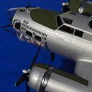
.thumb.jpg.ad2b820bfdebfdb8541e9255a05f38c7.jpg)
