Search the Community
Showing results for tags 'Airfix'.
-
I'm going to build this classic Airfix kit, with some improvements along the way. The livery is Alitalia, not the original pinstripe but the subsequent Landor scheme, thanks to these very good 26Decals. Quite busy at the moment with other GBs, I plan to start later.
-
 Hi all, The Airfix 1:72 Me-410 is finally complete! Started back in November '23, I got bogged down through Christmas and New Year, but here she is! Apart from the decals for this specific 410, everything is out of the box. I never make things easy for myself and this was very much the case when I saw this scheme on the Xtradecal sheet - I knew I had to attempt it! This is a fantastic new tooling from Airfix of a subject not very well covered in scale. There are signs in the kit that future variants may come (the A-3 Recon version would be very welcome)! As previously mentioned I slightly modified the kit to have the standard closed bomb bay doors to make this machine a true Me-410A-1 rather than the kit's A-1/U2 (or /U4). Hataka paints were used for this build for the majority with Mission Models US acrylic paints being the saviour to allow me to pull off the Wellenmuster camo using the re-fillable paint pen (see previous updates for details on this). These are some of my favourite photos of the build to upload now, but if the interest is there, I will upload the rest for everyone - let me know in the comments! A massive thank you to Phoenix Scale Publications for providing this sample at SMW'23 - this will be a full build article in a future issue! See you soon for the HobbyBoss 1:72 U-2A reveal!
- 19 replies
-
- 79
-

-
In the new (December) Airfix magazine is an announcement of a new Scale Modelling show, in conjunction with model railway, at the NEC in Birmingham 27/28 April next year. This is organised by Key Publishing, and I can't imagine that it is intended as a competitor to SMW and the Warley railway show at the NEC. I'm prepared to give it a punt, they are selling advance tickets now on the key underworld web site.
-
Hereby I present you another finished project; a Airfix Hawker Hunter F6 in 1/48. It's finished in the colours of 324 squadron, based at Leeuwarden airbase. You will have noticed that I've put on the wrong tail with parachute housing. Well... I thought it looked good, but I'm having doubts right now.. Will change that probably in the future. I've kept the other part.. build OOB with vallejo. Here are the pictures: Not 100% satisfied, but will try later. Thank you for looking!
-
 With the situation in Lebanon worsening, the British Govt decided to send an air support presence to the region in September 1983. Having considered the RAF’s other attack types, the Buccaneer was deemed most suitable because of its laser targeting capability. Six aircraft were dispatched to Akrotiri; three each from numbers 12 and 208 squadrons. Here is the full story for anyone interested in further reading. http://www.naval8-208-association.com/NewsArticlesOpPULSATOR01.html This is the new tool Airfix S.2B and it’s a superbly engineered kit and great fun to build. All of the parts fit together well and only minimal filler was required. The cockpit is already good so I didn’t use any aftermarket apart from the decals. There’s also a decent array of underwing stores included, all I needed to do was alter the Paveway so the main body was the same size as a standard 1,000 lb bomb. Thanks particularly to @Phone Phixer and @Selwyn during the WIP, especially regarding stores and flare dispensers, etc. WIP here: https://www.britmodeller.com/forums/index.php?/topic/235135865-from-one-bucc-to-the-next-…-‘pulsator’-pirate-148/ The real XX901 at Akrotiri during Operation Pulsator … Anyone have any yellow ‘901’ numbers they’d be willing to sell!?
 -
XW544 was an S2.B delivered to the Royal Air Force in 1972 and entered service with 15 Squadron at RAF Laarbruch. Here she is as at Luqa, 23rd May 1975. XW544 later moved to 16 Squadron in 1979, before returning to 15 Squadron in 1982. She spent many hours in the hangars due to fuel leaks and in only after a decade of flying, was withdrawn from service on 4 July 1983 into RAF Shawbury with 2227:10 hours of flight logged. The airframe was then placed into storage with its engines replaced with scrap ones, various other instruments were also removed to help keep the rest of the fleet flying. In 1984, XW544 was moved to No.2 School of Technical Training at RAF Cosford and gained the maintenance number 8857M. During its time at the SoTT, XW544 camouflage green was repainted, and 16 Squadron markings were readded. It also obtained a refuelling probe which it never flew or retired with. XW544 was seen at the RAF Cosford airshow in the 1990s alongside Buccaneer XW547 (now at Hendon).
-
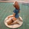
As one that doesn't normally build wingy things, after Santa had been to the Grandsons house, I had no choice but to venture into the aviation world and was ably helped and 'supervised' by him to build this. Straight out the box, painted with the supplied paints, although thinned with water and no weathering ...... Personally, I found this enjoyable, albeit fiddly as I'm not used too working at such a small scale and the Grandson seems happy with it ...... phew! Keith 😁
-
I really should not be doing this as it is totally insane, but as my Stirling build has gone quite quickly I may have a go at this. It is certainly big for its day and not small even by modern standards! Whether or not I complete it probably depends on the other kits I have to build and whether or not we get granted an extension to this GB but I will give it a go, The kit was first released in 1967 and I must have bought it straight away as I can remember getting it from the old Frizinghall model shop, later Frizinghall Model Railways, which was just round the corner from my school, which I left that year to go to Uni! The shop closed quite a while ago after the business moved to a warehouse. The model survived 2 house moves but was then knocked off a shelf and broken beyond repair though I still have quite a few of the bits, and this is a 2012 replacement boxing. The nice thing about this kit is that the various main wing sections are split into upper and lower halves and unusually for the time Airfix have provided holes and instructions for some rigging, however basic. As you can see from the box art there were either 2 or 3 wires in most cases but I will stick to just a single one for simplicity and speed - not accurate I know but at least it gives an impression of the real thing. There were originally 2 paint schemes - an PC-10 over natural linen one and a Post War Nivo ("Night Invisible Varnish-Orfordness" which was the result of testing at that establishment to find the best colour for night bombers) overall version though the reboxing has two in overall Hu155 pretending to be PC-10. Two types of roundel and fin flashes are provided but just the one set of aircraft ID markings for both which seems a bit strange, and there is also an optional big single 1650lb bomb to be carried externally if preferred, though I will probably go with the normal internal load. I have very little info on this machine so it will be OOB with rigging and maybe some replacement Aeroclub white metal Lewis Guns. Liked I said, it may not happen and I doubt it will be finished by the current deadline but what the heck! I like a challenge sometimes, particularly after the odd glass of "Scottish Wine".😄 I had hoped to build at least one of my "V Bombers" in this GB but I just don't have time. Pete
-
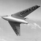
Gloster Javelin FAW9/9R (A12007) 1:48 Airfix The Gloster Javelin was an all-weather interceptor that started as an advanced concept just after WWII, but due to protracted design difficulties didn't see service until much later. It took until the FAW7 and the later FAW9 before it was capable of doing its intended job, and even then it was challenging to fly by all accounts. It was an important type for the RAF however, bridging the gap between the first generation and more recent designs by carrying external missiles, having afterburners for extra speed and in the R designated machines, the ability to refuel in the air using a long probe fitted over the starboard wing root. Its distinctive Delta wing with large T-tail made it easy to recognise, and it usually wore the familiar green/grey disruptive camouflage that typified Cold War era aircraft. Although it never fired a shot in anger, it had a reasonably long term of service for the period from 1956 to 1968, despite the rapid changes in aviation technology during the period. It was well liked by the crews, a solid performer at airshows, and was used by RAE as a test aircraft after some modifications, which included a rather colourful red and white paint job. The last aircraft flew in 1978, and there are thankfully a relatively large number preserved, with the majority being in the UK. Over 400 were made including all marks, and although there was some interest from some NATO countries, the Javelin was never an export success, with the RAF being its sole operator. The Kit This was and still is the first injection moulded styrene kit of this type in 1:48, although 1:72 has seen a couple over the years. Previously if you wanted one in this scale, you'd have to build a Dynavector vacform, which although an excellent kit is very hard to come by these days due to there being no possibility of a new supply. Having pored over the sprues for a while, the detail is a great example of the reinvigorated Airfix, and some additional parts have been included to display the model after construction and the whole package smacks of a company doing their best to raise their standards in every department. The kit arrives in a large top-opening box with a digital painting on the front, and inside are eight sprues of light grey styrene, a clear sprue, a large decal sheet, instruction booklet with colour painting guide at the rear and a separate A3 stencil guide. Construction begins with the nose gear bay, having separate detailed side walls and a satisfyingly deep depression in the roof for the wheel. This keys into the underside of the cockpit, which has a corresponding hump in the floor, showing how tight the spacing in that sleek nose was. The cockpit floor has built in side-consoles with raised instrument detailing on their topsides. The sides are blank however, but given the claustrophobia inspiring nature of the cockpit, it's doubtful anyone will ever notice once it is closed up. The rear bulkhead is a separate part, and one of the front console tops is too, with rudder and control column up front. The Martin-Baker Type 3J seats are built up from two halves that make up the frame, plus separate seat and back cushion parts, with a head box incorporating the prominent pull-handles attached to the top. They are well detailed, and the cushions have a slightly wavy material look to them, which makes them appear more naturalistic. There are no belts provided however, so you'll need to make your own from tape or foil, unless use an update set from Eduard. The instrument panels separate the pilot from the rear seater, and again there is good detail moulded in. It's perhaps not the most sophisticated instrument panel, having slightly simplified dials, but once painted and with the instrument dial decals installed it should suit most modellers, and with the lack of light in there, no-one will see. The cockpit sidewalls are supplied as inserts that cover the whole upper of the assembly, as well as providing the first sections of sill detail, and once the front bulkhead and the rear instrument coaming are installed, the outer skin of the nose is added, locating on a large lug low down on the front of the cockpit sidewall parts. The nosecone is added later in the build, and needs 25g of weight to keep all the wheels on the ground, but there's plenty of room in there for some dark matter. Next come the full-length intake trunks, which are supplied as horizontally split halves and terminate in the bullet-fairing and stator blades, with a reasonable representation of the front face of the engine behind them. Given the length of the intake trunking, it might be as well to paint it before assembly and try to get the best joint possible, particularly near the intake lip where it might be seen. Surprisingly, these attach to the sides of the nose assembly, and a double-yoke/wing spar part glues to the rear, keeping the engines at the correct orientation to the fuselage. The exhaust tubes are built in a similar fashion, but with the early afterburner nozzle at the forward end and an additional skin around the exhaust end, coupled with a one-piece set of "petals". These are secured in the lower fuselage with another double-yoke/wing spar part at the forward edge, with a resulting gap between the front and rear of the engine where the working parts would go on the real thing. With the insertion of the cockpit and engine trunking, the horizontally split fuselage is closed up, with a couple of optional holes drilled in the top before doing so. The texture of the fuselage is slightly different to the rest of the parts, and the guides for the wing spars have caused a few very light sink marks where the styrene has shrunk during cooling. It's neither massive nor deep, so you can fix them quickly with some Mr Surfacer or other filler, so don't tear your hair out. The intake lips are separate from the fuselage, and again there are a couple of sink marks around one side where the locating tab has resulted in extra volume of styrene, and subsequent shrinkage. Again, break out the filler, apply it sparingly and try not to fill any panel lines, preferably before gluing them to the fuselage. The large triangular main gear bays are moulded as a single part for each bay, but some ribbing detail has been added to the side walls, to prevent them looking too bland. A chordwise strengthening member is added to split the bay, and part of the retraction mechanism is glued to the roof before they are inserted into the upper wing. At this point you need to choose whether you are portraying the dive brakes/spoilers as open or closed, because there are different inserts for each option, and they sit toward the rear of the wing top and bottom parts. The ailerons are each two parts, and they are trapped between the wing halves to remain mobile if you feel the urge, but without sacrificing realism. The big T-tail can have its rudder and elevators movable too, and the massive fin glues into a deep slot on the back of the fuselage that should ensure it never comes off. The horizontal tail also rotates around a point roughly in the centre of its chord, which is achieved by the centre portion of the tail being modelled as a separate two-part section, the closing of which traps the stub axles of each side, with a large cylindrical nub holding them fast within the tail. The wings slide onto the fuselage along the two widely set spars, so if you've put the spars in the correct place (it's very hard not to), you should get good alignment. With main construction completed, it's onto the smaller parts, all of which would be broken off during painting if I was involved. It's a testament to Airfix trying to help the modeller by giving us a build process that matches real modelling, rather than something more convenient to the instruction designer. You have the option to close the gear bays and show your Javelin in flight, or you can use the stout gear legs to park her up in the cabinet. The main legs with their separate oleo-scissors fit firmly into a cupped slot in the gear bays, and the main retraction jack is fed through a strengthening beam and rotated into position, when it is joined by the remainder to link the bay roof to the leg. A pair of retraction jacks for the main door are moulded as a single C-shaped part, and they attach to the bay and the door, which should give you the correct angle without any effort. The outer bay doors both attach to the gear leg, with the only difference between port and starboard (apart from their handing) being a landing light on the port leg that isn't present on the starboard. The nose gear leg is a two-part affair, with a yoke and mudguard split so that the nose wheel is trapped between them. A Y-shaped retraction jack extends to the rear of the bay, and the two bay doors hang vertically (as shown in a scrap diagram) on three hinge tabs. Various intakes and exhausts are dotted around the underside and topside of the aircraft, most of which could be fitted before painting, as is the rear fairing behind the cockpit. The flaps, sited in front of the spoilers can be posed deployed or stowed at your whim, but the detail within the flap bay is too nice to hide away, so I'd be tempted to leave them open. A pair of jacks are included for each flap to set them at the correct angle and lend a little more realism, and this also follows through to the spoilers if you are leaving them open. If you've opted to display them closed, the insert mentioned earlier is all you have to add. If you have chosen to model them hanging out, the insert has the shape of the spoiler engraved deep into the surface, and the spoiler is a separate part with its two actuators glued to the inner face. There are four in total with one under and over each wing, so they should keep you busy for a few minutes. Another modeller friendly break in the build has you making up the four Firestreak missiles, four fuel tanks, or some combination, which is a task that so often gets forgotten until the last minute and consequentially sometimes gets abandoned due to burn-out. The Firestreaks each have two fins moulded into one half, and the other two as separate parts, plus a launch rail adapter and a faceted nose cone to finish them off. The fuel tanks are simple tubes with aerodynamically curved ends, and are made of two halves. There are four hard points under the wings, and you have a choice of three types of pylon on the inner stations, one each for Firestreaks, fuel tanks and unladen. On the outer station, only two choices are needed, with the missiles and tanks sharing one, and the other having no location pips for the empty option. Due to its prodigious thirst for fuel, the Javelin often carried two semi-conformal fuel tanks on the underside of the fuselage that were oval in plan, stowed side-by-side in the large flatter area under the engines. These are provided in the kit, and are single piece mouldings that hug the fuselage, with three locating pins to ensure they end up in the right place. The canopy, which is both thin and clear, is supplied in three parts, and can be posed open or closed, with separate side-rails that are attached to the edges of the cockpit, and pegs to link the glazing to the rails. It's clever, but it lends itself best to a closed canopy. If you're leaving the canopies open there's no benefit, as you still have to mask the front and rear rails, so you might as well glue the bottom rails to the canopy anyway. A pair of scrap diagrams show the correct positioning for the two sliding sections, and of course your windscreen will need fairing in with a bit of putty to replicate the real thing. Running alongside the cockpit and out over the wing beyond the tip of the nosecone, the refuelling probe is a large piece of kit, and is made from just two parts, which slots into one of the holes you made earlier in the top of the fuselage. A spigot pipe leads to the other hole (you did drill those holes, didn't you?), presumably to balance out the incoming fuel load. A pair of long pitot probes mount one on each wingtip, and that's the main build finished. Airfix have thoughtfully included some goodies to dress up your finished model to give it a little extra interest and realism. You get a pair of single part front intake FOD covers as well as another smaller pair for the rear, and a nicely detailed crew access ladder that curves gracefully over the large intakes to allow crew ingress and egress without resorting to contortionism. The steps, side supports, a platform and stabilising link to the bottom of the intake all build into a lovely little piece, which you can probably weather quite heavily to suit yourself. Markings The Javelin was usually found sporting green/grey uppers over a silver underside, but Airfix have also given the option of an all-over silver Squadron Leader's personal machine, which makes a nice change. You'll have to break out the masking tape and scratch-building skills if you want to do the red and white test airframe though, and who can blame them for not including it. You'll be pleased to know that the roundels have slots in them for the vortex generators on the upper wings, and they've even managed to include holes in the carrier film, so you'll be able to get them lined up in exactly the right place, and not have to flood the area with too much setting solution, which is always a little fraught. The big fin-flash for the tail is supplied as a single decal that folds over the leading edge, which leads to perfect alignment of both sides, but might be tricky for the less experienced decal user to wrangle. From the box you can build one of the following choices: FAW.9R No.64 Squadron, RAF Tengah, Singapore, 1960s FAW.9 Flown by Sq. Leader George H Beaton, CO of 228 OCU RAF Leuchars & Binbrook, 1966 FAW.9/9R 33 Squadron RAF Middleton St George, County Durham, England 1962 The third choice is now preserved at the Jet Age Museum at Gloucestershire Airport, Staverton, UK, so if you're nearby, you can go and see it anytime. The decal instructions are printed in colour on the back pages of the instruction booklet, and there is a separate A3 page showing the location of the stencils, to avoid cluttering of the main drawings. Decals are by Cartograf, which is a guarantee of good registration, sharpness and colour density, with a thin gloss carrier film cut close to the printed areas. Conclusion I was really excited by the announcement of the initial boxing of this kit, and it’s great to see it back in the catalogue again. Airfix have been raising the quality bar with almost every release, and this kit’s moulding is excellent, the detail is good, and the part count is commensurately high without delving into the realms of "over engineering". The inclusion of a set of FOD guards and a crew ladder just adds to the value, as well as the overall appeal of the kit, and including a non-camo decal choice is a good plan. If you avail yourself of a set of Xtradecal serials (X48044) that have been reprinted so should be readily available, you should be able to portray almost all of the fleet, with the exception of the "funnies" like the aforementioned red/white machine. Very highly recommended. Review sample courtesy of
-
In September 2023, Airfix researchers visited Flysamlingen at Gardermoen (at Oslo airport) for another scanning session. Previous visits have resulted in kits like Heinkel He 111P (1:72); F-86F and Vampire Mk.III (both in 1:48). I don`t know what aircraft they scanned - and the ones who know won`t tell. Personally, I would really like to see a Ju 52/3m done by the current Airfix team. On display are: https://flysamlingen.no/utstillingen/flyene/ Rumpler Taube Farman F.46 BE. 2f - can use parts from Airfix BE 2c Auster J/1 Autocrat Fairchild M-62 (PT-19 and PT-26B) Interstate S.1A Cadet Northrop N-3PB kitted by MPM Noorduyn Norseman Mk.IV coming from Ukraine Lockheed C-60A Lodestar kitted by MPM Douglas C-47A Skytrain (Dakota) recently kitted by Airfix. Junkers Ju 88A-1 is still undergoing restoration and not assembled. Junkers Ju 52/3m missing a decent Ju 52/3m, the aircraft in Flysamlingen is an original German built example. Heinkel He 111P-2 scanned and kitted by Airfix Supermarine Spitfire PR XI - easily available to scan in England. Piper L-18C Super Cub SAAB 91B-2 Safir Cessna O-1A Birddog De Havilland Vampire F.3 scanned and kitted by Airfix De Havilland Vampire T.55 getting kitted by Pilot Replicas Lockheed T-33A Republic F-84G Thunderjet Republic RF-84F Thunderflash North American F-86F Sabre scanned and kitted by Airfix North American F-86K Sabre Canadair CF-104 Starfighter Lockheed TF-104G Starfighter Northrop F-5A(G) Freedom Fighter Northrop RF-5A(G) Freedom Fighter Northrop F-5B(G) Freedom Fighter General Dynamics / Lockheed Martin F-16 AM De Havilland of Canada DHC-6 Twin Otter Lockheed C-130H Hercules also available at Cosford. Bell 47D-1 Sikorsky H-19D-4 Chickasaw Bell UH-1B Iroquois Westland Lynx Mk. 86 Westland Sea King Mk.43 recently done by Airfix in 1:48 & 1:72.
-
Having just finished Airfix’s superb Royal Navy Buccaneer, I couldn’t wait to start an even newer kit, of the 1/48 RAF’s S.2B version. The sprues are pretty much the same but with a bulged bomb bay (that I won’t use as this one will be open too) and handily an ECM pod, AIM-9 and Paveway LGB as used in Operation Pulsator, the deployment of six RAF Buccaneers to Akrotiri in 1983 to support the British Army peacekeeping force based in Beirut. These jets flew at ultra low level through (rather than ‘over’!) the streets of Beirut to deter terrorist attacks on the UK contingent. There’s a fascinating account of this deployment here: http://www.naval8-208-association.com/NewsArticlesOpPULSATOR01.html This will be my chosen aircraft; XX901 of 208 Sqn: I’ll need some aftermarket decals for this one, plus an extra Paveway LGB from somewhere (only seems to be one in the kit that I can see). I’m also going to stick four 1,000lb bombs in the open bomb bay. I bought an Xtradecal sheet for the underwing serial. I need two yellow ‘0’s for the tail fin but I’ll worry about that later! This will come in handy, particularly for the Pulsator weapons loadout. Tally ho! …
- 50 replies
-
- 11
-
-
Fairey Gannet AS.4, 815 Naval Air Squadron, HMS Ark Royal, 1958. The new Airfix kit, OOB painted with Humbrol, Vallejo, and Revell acrylics.
- 23 replies
-
- 64
-
-

-
I have been eying on an A-4 for long time, not sure which brand and scale to start. And when I came across the Airfix 1/72 A-4B, I think it is the ONE ! If you are interested on the build process, please refer to here : and here is the final outcome after quite some months of work, total about 21 hours spent. The only upgrade part is the resin ejection seat. Hope you like it and as usual, welcome for comments and suggestions. Thanks for reading A little video :
- 15 replies
-
- 36
-
-
iBristol Bloodhound (A02309V) 1:76 Airfix Vintage Classics Following the cancellation of an earlier Ramjet-powered Surface-to-Air missile project by the name of Blue Envoy, due it seems to the 1957 Defence White Paper by the now-infamous Duncan Sandys, a shorter-range project was considered to pick-off the remaining enemy bombers that made it past the English Electric Lightnings that were responsible for point-defence of the Great British airspace. The fact that the Blue Envoy project had been progressing well, with successful trials of a scale-version of the missile, caused some scratching of heads, but the new Bloodhound missile benefitted from its technology, giving it a head start on its development path. Much of those technology benefits were incorporated into the Mark.II Bloodhound, extending its range to almost double that of the Mk.I. When launched, the missile accelerated incredibly quickly thanks to the four booster rockets that were ejected after only three seconds, by which time it would be travelling at an ear-popping 1,800mph, with attendant sonic boom in addition to the roar of the rockets and ramjets, making hearing defence an absolute necessity. It homed in on its target using a combination of semi-active radar and powerful computing capability (for the day) that gave it a high level of resistance to electronic countermeasures, and allowed it to accurately track low altitude targets, making it a lethal opponent for the expected waves of lumbering Soviet bombers and their escorts in the days before ICBMs took over the role of delivering nuclear weapons. It remained in service with the British and Swedes until the 90s due to its abilities, and Britain took their Bloodhounds out of service when the Berlin wall came down, while the Swedes kept theirs until just before the new millennium. The Bloodhounds first paired with the Thunderbird shorter range missile and then the Rapier that covered the required defensive envelope between them. The smaller missiles could also be transported comparatively easily, while the Bloodhound was of a size that lent itself to fixed installation, often around strategic areas such as airfields. The Swedish Bloodhounds were converted to be vehicle transportable, and a possible future development of the missile was to introduce this facility wholesale to the Mk.IV, while the Mk.III was to be nuclear tipped with a longer range that would presumably be used to thin the bomber stream over the sea, hopefully keeping any fall-out away from the land. Both those variants weren’t completed however. The Kit This kit was first released in 1960 when the missile itself was still new. It has been reboxed several times since then, and up until the announcement of its long-overdue re-release, it was achieving eye-watering prices on a certain auction site. It’s amazing how some people are prepared to throw money at something if they want it badly enough. Now that it is back in Airfix’s catalogue under the Vintage Classics line, there will be a few people feeling a little silly, but the rest of us will just be glad to see it again, and pleased that the moulds are still in good condition. I built one myself as a nipper, and remember it fondly. Where my kit went though, I have no idea. The kit arrives in a diminutive red-themed top-opening box, and inside are six sprues of various sizes in the new darker grey styrene that Airfix have been using, which has been well-received. There are no decals, but there is a Land Rover with missile trailer, and a set of figures to guard the emplacement, including a dog that one of the chaps has on an invisible lead. Detail on the missile is good, and once the seams are dealt with, it should look suitably sleek. The trailer is a nice inclusion, as is the Landy, but if you want to give it an improved look, you might consider adding some clear acetate windscreens, a bulkhead and a couple of seats for the crew, or at least the impression of those things. There are of course some ejector-pin marks here and there, most annoyingly on the canvas roof of the Land Rover, which will make careful removal and making good very important. There is surprisingly little flash too, most of it around the sprue runners and the figures, which should be quick enough to remove with the edge of a sharp blade and some fine sanding. Construction begins with the missile, joining the main halves that includes the two Bristol Thor ramjet engines, then adding delta-shaped steering fins forward and square fins to the rear, plus the support structure for the temporary boosters in the form of a cruciform part at the rear of the missile. Each Gosling booster rocket is made from two halves, one of which has the fin moulded-in, and once complete the quartet are joined to the main body on lugs near the front fins, and at the rear on the four points of the cross. In action, the rockets were hooked to a ring fore and aft, and once their thrust became less than the ramjets, they would slide backwards, opening like a set of petals before falling away. That’s the missile finished. The Land Rover is next, building the canvas-topped bodywork onto a flat-bottomed floor, adding the windscreen, bonnet and radiator assembly to the front, plus two axles that thread through holes in the arches, to be finished by adding wheels to each end of the axles. A scrap diagram shows that if you leave the glue off, the wheels should rotate. At the back of the vehicle a bulkhead with a notch for the towing hitch closes the rear. The launch platform has several parts left unglued to allow it to be moved, based upon a flat turntable, which is joined to the floor by a styrene pin that joins them together and allows them to rotate. The side walls trap the launch rails and their supports into position, adding extra supports as the parts are joined together, and finally a stopper pin that plugs into the back of the missile so it stays in position. The last main assembly is the trailer, the chassis made from two halves that trap the tread-plated floor in position, adding twin wheels into the rear arches on both sides, another frame is glued to the trailer’s gooseneck, and twin supports are added fore and aft. The front wheels are based on a pivoting platform secured in position by another styrene pin, adding two stub axles beneath that have more pins to hold the wheels in place, and an A-frame with towing eye on the front. There are five human figures and a dog on the sprues, although you only use three of them according to the instructions. One is an officer waving while a ‘Snowdrop’ RAF MP stands to attention, and a dog-handler should be linked to the dog via a fine wire so it doesn’t bite anyone. The other two dog-handlers don’t have a dog to handle, but you could adapt them to other poses if you feel the urge. Markings As already mentioned, there is only one colour scheme depicted, which consists of a white missile with yellow boosters, green launch platform and trailer, and an RAF blue Land Rover. Other schemes were used, so check your reference if you feel like a change. Conclusion A great many modellers have been waiting for this kit to come back in stock, and unlike those with bottomless pockets, we appreciate the reasonable price that it is now being offered at. Most of us won’t notice the slight difference in scale from the usual 1:72, and if you give it some care and attention, you should end up with a creditable replica of this Cold War Warrior. Highly recommended. Review sample courtesy of
-
Hello everyone and Happy New Year (if I'm not too late to say that). I could hardly wait to get started on this GB because I haven't had a modelling table since just before Telford and the withdrawal symptoms were setting in! I had to wait a day or 2 extra until I could establish my new place to mangle plastic. It's not the kitchen table anymore but still not actually permanent (it'll have to be tidied a bit if Daughter no. 3 suddenly decides to visit) but better than before. So I'm excited ...... So to begin. I aim to contribute 2 builds for this GB, both of which are older Airfix I have chosen to do the Hs 129 first as i think it will be quicker because I don't intend to get bogged down in internal details (I'll believe that when I see it ) as little is likely to be seen through the limited cockpit glazing. AND I'm awaiting some AM for the Mosquito that I'll be doing as the MkXVIII. Doing both with big guns sort of balances out I think. Should be fun anyway as I don't really know too much about the subjects and will hopefully learn new things. For this build I'll be taking a lot of direction from this build https://www.britmodeller.com/forums/index.php?/topic/235041344-172-henschel-hs-129-done/ that I found when digging around for info. Thanks @Dermo245 hope it's ok. The box I have for this kit appears to be the first issue (according to Scalemates) from when the kit came out in 1968. I actually bought it about 10 years after that from a place near Halifax or Keighley (can't quite remember) called MHW Models. I haven't been over that way for many years but I don't think they are trading any more. It has been kept dry in the loft and seems to be in reasonable nick, although there's a worrying bend on the "Big Gun" which I'll have to look at (maybe it was for shooting around corners ? ). The decals must be a bit of a worry but they could potentially be ok. I used some last year of a similar vintage without too much trouble. I have some spares somewhere if not. The painting bit refers to Airfix enamel colours. I actually still have some tins from my former modelling life but not opened them yet. Maybe I'll have a look, but I thought them more appropriate for the Classic Aifix GB later in the year. Anyway, thanks for looking. Just off to give the sprues a bath. More later hopefully. cheers Rob
- 77 replies
-
- 29
-
-
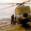 As someone who made a (very small) contribution to the research into Airfix's new 1/48 Sea King, I was lucky enough to be invited to the launch event at Historic Helicopters near Chard yesterday and, like everyone there, I came away with a kit. I think it's going to be in the shops pretty soon (I seem to recall August being mentioned), but judging by the thread in The Rumourmonger yesterday there is a lot of interest in this kit, so I thought I'd build it ASAP. [Sorry, Ark Royal fans; back burner again for a while - but in truth my mojo has been massively dented in recent months because of this blasted court case, so I rather welcome a chance to get the old creative juices going again!] Long term BM members will already know that I have 'form' when it comes to 1/48 Sea Kings - specifically a long-running (and as yet unfinished) saga converting the Hasegawa 1/48 kit (until yesterday, the only game in town in this scale) into the HAS5 that I ditched in 1988 Though some "sprue shots" have already been posted in the Rumourmonger section, I will start with a full set: Sprue A, mostly the inner shell (Airfix have taken the same approach as they did with their excellent 1/48 Lynx kit, providing an inner box that sits inside the fuselage) The floor is particularly nicely done, I'd say, with the characteristic access panels to the fuel tanks etc faithfully rendered: The kit provides the parts to build an HAS1, HAS5 & HU5 (all the same airframe, XV666 - known throughout the Fleet Air Arm as "Damien") - you could also easily build an HAS2 provided you could access appropriate markings, and no doubt the after-market designers are busy as we speak. One of the real features of this kit is the fact that it has a full interior (Hasegawa's has absolutely nothing behind the two pilots' seats), so to allow the wide variation in internal fittings between the stages of Damien's life, the underside of this floor part is marked with numerous holes: ...and the instructions tell you what to remove for which version: Sprue B: Sprue C Sprue D - both metal & composite blades, the 6-bladed tail rotor (5-bladed on a different sprue), plus some of the main rotor head: Sprue E - sponsons, undercarriage & the "pit-head gear" (sonar winch) Sprue F - 5-bladed tail rotor, seats, underside of boat hull, more sonar stuff Sprue G - internals, mostly: Finally Sprue X for the clear parts: Lots of people have already been asking about future releases (HAR3 & HC4 in particular). The Airfix guys were predictably non-committal yesterday, but there are obvious indications that both 3 & 4 (and I suspect at least one "export versions" boxing) will follow in due course; notably the window openings in the fuselage halves, but also the fact that there are parts for the so-called "Commando step" (which was only fitted to the HC4) - the smaller "SAR step" as fitted to the HU5 is also provided. The Eagle-eyed among you might also have noticed these IR jammer parts on the clear sprue (sorry photo is a bit blurred!) - as far as I know these were only ever carried by the HC4 More follows once I have had mi lunch! Crisp
- 324 replies
-
- 51
-
-
-
Bond Bug (A02413V) 1:32 Airfix Vintage Classics The Bond Bug was designed by Ogle Design for Reliant, the famous 3-wheel car manufacturers in the early 70s, and it was a true child of that era, as well as having three wheels like the majority of Reliant’s other output. It was a distinctive vehicle, most of which were made in a vibrant tangerine orange, although a few were built in a bilious green for a change. There were even a few four-wheelers, although those were aftermarket conversions. Reliant first bought Bond Cars, and in order to prevent possible harm to their brand (were they serious?), they decided to press forward with the concept that had been wallowing in design form only under the Bond name. It ran on a shortened chassis that had been developed for their soon-to-be-released Regal, and ran with a 700cc petrol engine that was surprisingly mounted in the front and output a neck-braking 29hp initially, although an extra 2hp were squeezed out of it for the supposedly upmarket ES variant, although it came with a little extra torque to convince you that you were going fast. There was a comfort difference between the standard model and the ES too, with better seats and a few more bells and whistles. Despite the flurry of publicity, the sales never materialised, and the proposed upgrades to a more powerful engine were shelved, as were the 4-wheel drive option, which materialised later as a kit once the Websters owned the rights to the Bug. It utilised the sub-frame from a Mini, and could be bought as a small kit that needed a Reliant 3-wheeler, or as a full kit with all the parts included. It is understood that fewer than 30 kits were sold, so they’re quite rare. Webster also produced a few of the original design Bugs. In the 90s, a revamped Bug with four-wheel drive was in development, but Reliant got cold feet and it never reached production. The market for Bond Bugs has been buoyant since they passed into history, with the nostalgia factor increasing prices, and the availability of parts allowing owners to keep their cars in working order. It didn’t hurt that the bodywork was all fibreglass, and didn’t rust like most 70s vehicles. The Kit Airfix made the original tooling of this kit in 1971, soon after the launch of the real one, and was last seen being sold new in model shops in 1975, as evidenced by the large copyright stamp in the roof lining. It has been missing from Airfix’s line-up since then, with the second-hand market the only place they were available up until now. The re-launch has not been just a case of reboxing the old styrene either. There has been work done to improve the glazing of the model, which is usually a weak-point of older toolings. The newly designed and tooled glazing replicates the clear plastic side windows and black vinyl lowers to the doors along with the rest of the clear parts, redone for the new millennium. The tooling has clearly been kept in good condition with good detail visible, just the layout of the sprues and the raised part numbers on the larger parts flagging it as a child of the 70s. The kit arrives in a small top-opening box, and inside are four sprues of grey styrene, plus a sprue of clear parts, decal sheet and the instruction booklet, which is concertina-fold and printed in spot colour. Construction begins with the two chassis rails, which are linked together by four cross-braces with the rear axle mounted on a pair of U-supports and a coil-spring that is surprisingly well moulded. At the front, a swing-arm is fitted with another coil-spring and damping arms, then the engine is built from seven parts plus a short drive-shaft that links it to the transmission in the centre of the rear axle. The radiator core is fitted under the upper bodyshell, which together with the lower encapsulates the chassis, adding a bulkhead and fuel tank to the rear. The steering column, wheel, stalks, gear stick, foot pedals and handbrake are all installed in the cabin, adding a simple console to the centre console, and the very 70s-looking driver if you use him sits in the right seat, adding his arms to grasp the wheel. Underneath is the puny exhaust pipe with muffler that has a scrap diagram showing its location once complete. The upper cowling has the windscreen and doors glued in place, and if you want to go for a little more realism, you can also remove the Airfix logo from the head liner. At the rear of the body there is a long lozenge-shaped rear window with the light clusters below, and more clear parts for the headlamps and side-lights in the bumper. The three wheels are each made from the main tyre and rear hub, plus a well-detailed outer hub that traps a washer inside to allow the wheels to rotate if you are careful with the glue. That’s it. You’ve just built a classic kit. It's not a large model Markings The Bug was predominantly painted in tangerine orange from the factory, but if you want to stamp your identity on it, you can paint it any colour you like. There are two number plate options, one of which is the BUG 700 plate, plus EEV 589, and while the significance of the first one is fairly obvious, the other isn’t – to this modeller at least. Decals are by Cartograf, which is a guarantee of good registration, sharpness and colour density, with a thin gloss carrier film cut close to the printed areas. Conclusion Whilst this isn’t the dominant scale in the car modelling world, it’s good to have it back in service, and looking like it is ready to be built. It has sold plenty in pre-order, so don’t hang about if you want one. Very highly recommended because it’s fun! Review sample courtesy of
-
Started another Airfix small kit 1/72 A-4B or Q Trial build shows that the fitting of fuselage is not bad. Only option part is the resin ejection seat. Applied a mixture of german grey + Gaia 072 on cockpit area, GSI c156 on the inner wall / structure of air intake and nose wheel well, Modo MX-02 on the inner surface of exhaust, and Modo T-024 on the fans. The resin seat has been filed to fit the height of the cockpit and not exceeding the height of the wall behind the seat. Will have to test fit with the canopy in close position after fuselage combined. For time being, applied german grey as back color and Gaia 072 as highlight. Applied decals on cockpit. Installed both air intake before fuselage combined, and installed the exhaust and air intake inner structure on to the left side of fuselage. Control stick is hand brush with grey, black and white. Installed it into position and ensure it will not block the ejection seat installation in future. Installed some weight (about 5-6g) inside the nose as this kit sure will sit on its tail otherwise. The main landing gear wells have some details while the nose gear well is relatively "empty", added some 0.2mm wire inside. It is time to close the fuselage and the drop tank. Putty and sanding time. Adding the rest of wings and fuselage parts to make it look like a A-4 Overall the seams are manageable. The wings are almost perfectly fitted without filler, however, there is a gap in front of and after cockpit, and another one in front of nose gear well and around the gun holders on both wing roots. Applied some green stuff putty and clean the excessive putty with cotton stick with water. Wait for next steps.
-
Gidday All, 1/600 scale warships are my modeling interest, and since progressing from OOB builds I usually try to make various ships that actually existed. However, I sometimes make whiff ships also, and when I do I try to make them as plausible as possible. To date I think I've made seven (eleven as at Feb 2024), the first nigh on 20 years ago. This was waaay before I even knew of the term 'what-ifs', or modeling forums such as this. This first was a battleship I named HMS Monarch, and was made from two Airfix KGV kits. I decided to make a ship with four quadruple 14-inch turrets. Here is a photo of one such kit, built OOB, and shows what I started with. This meant that the bridge superstructure had to be moved aft a little, to accommodate the larger "B" turret. Also a complete extra turret was added aft, hence the hull needed to be lengthened somewhat. I also removed the aircraft launching and recovery arrangements, rearranged the boat stowage and added more light weapons. Here she is, the battleship whiffed from two KGV. Quite powerful in fact. The two hull halves were joined midships but the deck was joined just fwd of 'X' turret. I also added quite a few light AA guns, as you can see. I'll add more at a later date. Regards, Jeff.
-
Sounds like there might be quite a few B-25s in this Group Build, so I'll be adding another. Using the recent new tooling from Airfix, I'll be building the B-25D "Grumpy", an airworthy B-25 that has a history of flying both in Europe and the US. It was just sold in September and will be returning to Europe next year. A bit of its history can be found here https://b-25history.org/aircraft/433318.htm Box pictures, still getting the correct decals. Looking forward to this, as I've yet to build the Airfix version, which im hoping is a better build than the Hasegawa offering.
- 15 replies
-
- 15
-
-
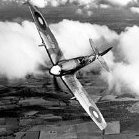
 Gentlemen, As a result of a combination of circumstances I am going to build a section of Spitfires, the Mk.I of course, which as eny fule no is the most perfectly beautiful of all the Spitfires and I will brook no argument on this. The aforementioned circumstances, on the offchance that you are interested, include (but are probably not limited to) the following: The BoB 75 Anniversary Group Build is looming large on the horizon and I have about 30 more suitable kits in the stash than I can reasonably expect to build in the allocated time period, so need to do some deck clearing; The Heller Bloch MB210 I am supposed to be building for the French Fancies Group Build is an unpleasant clunky sink-marked flashed monstrosity made out of plastic that does not so much separate from the sprue as explosively disconnect and frankly I need some displacement activity to avoid working on it; Although I built a fair number of the old-tool Airfix Spitfire Mk.I I have never built the 'new' tool one, and this is a bit of an oversight as it can barely be described as a 'new' tooling any more; The new Xtradecals BoB Spitfires sheet arrived yesterday and I am very nearly bursting to build some of the options on it, in the knowledge that there is a second set on the way and I will want to build a few of those as well... So with my intentions adequately justified - to myself at least - I selected these from the stash: ... along with the Xtradecals set and Eduard canopy masks: ... and these are the options I have chosen... P9323 ZDoF of 222 Squadron, RAF Hornchurch... ... X4593 UOoA of 266 Squadron, RAF Wittering, and RNoN (serial presumably overpainted) of 72 Squadron, RAF Leconfield, which was flown by Australian ace Des Sheen. I hope to build these in parallel and save myself a certain amount of work and will make a start later today. Cheers, Stew
- 476 replies
-
- 14
-
-
Hi! Let me present you my latest completed tank - the Churchill Crocodile. The kit is contains two different aged part spues, the older one dates back to 1961 (!) and the "Crocodile" trailer is from the year 2005 (taken fron Scalemates). It was a fast fun build, with intention to commemorate the D-Day 80th Anniversary. I added up many small photoetched, resin and 3D print details, just to improve the overall impresion. I hope you'll like it Have a nice week!
-
Gloster Meteor F.8 (A09182A) 1:48 Airfix The Gloster Meteor was the first British active-service jet fighter, and the Allies' first operational jet aircraft during the Second World War. The Meteor's development was heavily reliant on its ground-breaking turbojet engines, pioneered by Sir Frank Whittle and his company, Power Jets Ltd. Development of the aircraft itself began in 1940, although work on the engines had been underway since 1936 using the diminutive E.28/39 Pioneer airframe. The Meteor first flew in 1943 and commenced operations on 27th July 1944 with No. 616 Squadron RAF, although it was initially forbidden from operating over enemy territory for fear of a downed aircraft giving away precious secrets. Nicknamed the "Meatbox", the Meteor was not a sophisticated aircraft in terms of its aerodynamics or engines, but proved to be a successful combat fighter through successive upgrades of the basic design, with several major variants incorporating rapid technological advances during the 1940s and 1950s. Thousands of Meteors were built to fly with the RAF and other air forces, and remained in use for several decades overseas. The Meteor saw limited action in the Second World War, primarily intercepting V-1 ‘Buzz Bombs’ as they flew over the British coast, which was a task they were well-suited to. The F.4 was the first major variant after the initial wartime variant, and by the time the F.8, which is considered by many to be the definitive variant, came into service the airframe had been subject to substantial upgrades, shortening the wings that mounted more powerful Derwent 8 engines, lengthening the fuselage by over 30 inches, greater capacity fuel load, and a new tail to improve aerodynamics and prevent instability when ammunition was fully expended. It was also fitted with a Martin-Baker ejection seat, starting with a Mk.1 that was superseded by the Mk.2 later in production. Meteors of the Royal Australian Air Force (RAAF) provided a significant contribution in the Korean War, flying many sorties against Mig-15s that were superior in most respects, suffering mounting losses before they were re-tasked with ground attack roles where they excelled due to their ruggedness. Several other operators such as Argentina, Egypt and Israel flew Meteors in later regional conflicts with variable success dependent upon the opponents that they flew against. Specialised variants of the Meteor were developed for use in photo-reconnaissance and as night fighters before they became too slow and vulnerable to the more modern, swept-wing aircraft that were coming into service. The Kit This is a reboxing of the new tooling that was initially released in 2016, and is the third boxing of the F.8, with another boxing adding parts to make an armed-recon variant of the F.8 called the FR.9. The kit arrives in Arfix’s red-themed top-opening box, and inside are five sprues in dark grey styrene, a sprue of clear parts, decal sheet, instruction booklet with greyscale stencil diagrams on the rear page, and a separate folded A4 sheet of profiles in full colour that has been printed on both sides of the glossy paper. Detail is good, with the mouldings crisp, extending into the usual focal-points of cockpit and gear bays, plus cannon installations in the cheeks of the nose, and a pair of Rolls Royce engines that can either be fitted into position in the nacelles, or mounted on a trestle that is included in the kit. Construction begins with the cockpit, although it isn’t based around the usual tub, but is instead made from a floor with two holes moulded-in, plus two sidewalls that are loaded with detail. The two walls and floor are joined together to make a tub of sorts, and have the gun bays installed on the outer faces, followed by a detailed rear deck, and the nose wheel well under the floor. The supplied seat is a Mk.2, and is built from two halves that make up the chassis, adding the launch rail behind, and a choice of seat pads with or without moulded-in belts. The top of the headbox is separate, and has the pull-handle moulded-in, plus a pair of stencil decals on either side of the box that will be seen through the cockpit glazing. It is fixed into position on the sloped rear of the cockpit, locating on a pair of tabs, then adding the control column and the instrument panel to the front, including another decal to depict the dials. A bulkhead is inserted into the front of the cockpit assembly to complete the interior, with a side-view showing how it fits to the sidewalls. If you plan to cover the gun bays with panels, you can skip building the guns, but if you intend to depict them, each one is made from a breech with barrel, and a two-part drum magazine on the top, fitting cartridge ejector chutes over them once they are embedded in the bays. The gear-up option couldn’t be simpler, inserting the bay doors with lips into the full-span lower wing part before proceeding to installation of the forward spar, then the rear spar, which has an engine nacelle bulkhead at each end. If you plan on mounting your model on an Airfix stand, there are two 2mm holes to be drilled in the centreline, with four more holes if you plan on using the belly tank instead, and two more under each wing for the drop tanks. The gear bays are then boxed-in for the gear-down option in by adding side walls between the spars, and dropping a roof over them after painting everything aluminium and weathering it as you see fit. Two exhaust tubes are fabricated from halves and are painted gun-metal, mounting in the rear of the nacelles on two pegs in the spar and a lug under the end of the tubes. A small part is fitted inside the outer wing panels in a raised bracket, adding a landing light in a hole under the port side, closing the assembly by adding the upper wings. At this stage the fuselage is still open, which is unusual for your average fighter model, but we go back to that now to complete that task, starting with a clear part in the left side. The cockpit/nose-wheel assembly is shown in a scrap diagram to assist with painting the interior with more aluminium, cutting a small notch in both sides at the bottom, and drilling out a 0.8mm hole if you intend to deploy the crew foot-step. You are instructed to add 15g of weight into a cubby under the rear of the cockpit, so use your favourite heavy thing here, although you might want to first perform an internet search on the dangers of using lead in models, and their reactions with some glues, so I’m told. The fuselage halves are then brought together, cutting another nick in the starboard spine before you apply glue, and dealing with the seams in your preferred manner, followed by two root fairings to the rear of the wing cut-outs, with a scrap diagram showing the correct angle to set them from the front. The lower wing can then be mated to the fuselage underside, starting with the leading-edge and lowering the trailing edges onto the root-fairings to ensure a good fit, so it’s crucial that the glue has set properly on those fairings before you apply any pressure. The rudder is in two halves due to the unusual tail design, and the lower panel is made from two halves and installed without glue, the single-part upper panel is then lowered into position, gluing the two assemblies together via the long peg moulded into the upper section, which should result in them pivoting in unison. The elevators are each made from two halves, with a single-part flying surface glued to the trailing edge once they are plugged into the slots in the bullet fairing on the fin. The ailerons are also made from two halves, and like the elevators, can be posed deflected if you wish. Now that the wings are together, the intakes are each built from an inner and outer surface before they are slotted over the leading edge of the wing, painting the inner face gun metal. You now have three choices of how to pose the engine nacelle covers and the engines within. The sleek covered look just involves the two curved cowlings and engines painted at the front, taking care to align the panels carefully to minimise clean-up later. The next option is to expose the engines in position within the nacelles, while the final option is to have one engine out and on a stand that can be posed near the aircraft. Two engines must be built first unless you are going off-piste and combining some of the options, each one is made from eight parts, depicting the scaled-down Nene that was known as the Derwent, still utilising centrifugal technology while the rest of the world was working on axial flow. The trestle is made from a further five parts, and the external engine is then fitted with the prominent ancillary pack that fixes to a lug on the front of the assembly. To mount the engines in the airframe, the accessory pack is left off while the engines are inserted into their nacelles, fixing the pack in the front once they are glued down. The nacelles are then either closed with the panels, or if you plan on leaving them open, a hoop and two snaking hoses are added over the engine, cutting the small section of sprue between the hoses once it is in place, cleaning up the gate, and touching in the paint. Flipping the model over, the gear bays are detailed with hoses that cross the front of the bay, and have small details moulded into them. While the model is inverted you can fit the centreline tank on the four holes that were drilled earlier, then work can begin on the main gear. The wheels are supplied as two halves each, with a flat-spot moulded into the bottom to depict the aircraft’s weight on the rubber. It’s best to deal with the seams and paint them before you join the two halves of the gear legs with their integral mudguards around them, painting the insides of the guards aluminium at the same time. The completed gear legs are then inserted into their respective bays, and an X-shaped pair of retraction jacks, the uppermost jack opening and closing the inner gear bay door, which is fitted next, and is accompanied by the outer door that fixed next to the engine nacelle. The nose cone is made from two parts, and is set aside while the glue dries, and if you have chosen the gear-up option, the nose gear bay is closed by inserting the rear door insert into the fuselage, slipping the front door into the nose cone before it is glued to the front of the fuselage. For the wheels-down option, the forward section of the bay isn’t a bay at all, it’s a hollow nose cone that contains a two-part gear leg and its retraction mechanism mounted to the bulkhead at the front of the fuselage. The lower section of the nose gear leg closes around a single-part wheel, and inserts into the upper leg, fixing it in place on the bulkhead before putting the nose cone into place, taking care with the alignment. The two rear bay doors fit on either side of the part of the bay where the wheel is stowed in flight. While the model is upside down, you can fit the air-brake panels deployed or flush, painting the undersides gun-metal if you pose them open. There is another pair on the upper wings with the same paint used as on the undersides. The engines are completed by installing two short cylindrical exhausts in the rear of the nacelles, fitting the gun bay doors if you need them, and adding a clear gunsight into the front of the cockpit. There is still a little work left to do, first on the underside, where the shell-ejector ports are installed in recesses under the cockpit, plus a few small aerials and the wing drop-tanks, which the instructions advise to glue in place after applying the underwing serial decals. The crew step is inserted into the hole drilled earlier if you are building your model on the ground. Flipping the airframe over, there is a blade aerial on the spine, plus a pitot probe inserted into the port wingtip, after which the canopy parts are prepared for installation. The windscreen has a frame inserted into the base, which includes de-misting tubes and other parts, while the canopy has a stiffening floor fixed to the rear portion, remembering to paint it black before you install it. The windscreen is glued into the front of the cockpit with your favourite non-fogging glue, and the canopy can be closed by butting it up against the screen, or pushed back to admit the pilot, with a pair of scrap diagrams showing the correct positions. Markings There are two decal options on the sheet, and each wears a substantially different scheme of an acrobatic team from the period, for a nice change from the norm. As already mentioned, the stencils are covered on the rear page of the instruction booklet, and there are quite a few of them, which is a minor surprise for a first generation jet. From the box you can build one of the following: Evergreen Display Team, College of Air Warfare, RAF, 1963-64 The Meteorites Acrobatic Team, RAAF Williamstown, 1956 Decals are by Airfix’s usual partners Cartograf, which is a guarantee of good registration, sharpness and colour density, with a thin gloss carrier film cut close to the printed areas. Conclusion It’s a welcome re-release of this recent tooling, and has some interesting decal options, which although they won’t appeal to everyone, broadens the range available, and there are plenty of aftermarket options out there if you feel the urge. Highly recommended. Review sample courtesy of
-
My first attempt at one of the new-tool Airfix 1/48 Buccaneers, and I thought I’d start with the Royal Navy version. I have to say it’s an absolutely superb kit, Airfix’s engineering is brilliant and required only a few areas of filler. The fit is excellent with many parts just dropping into place. I didn’t need to use any aftermarket as the cockpit, decals, undercarriage, etc are all great out of the box. XV340 was delivered to the Fleet Air Arm in April 1967, and served on board HMS Eagle and Ark Royal as well as at Lossiemouth. It was transferred to the RAF in May 1973 but was grounded following the Buccaneer fleet inspection in 1980 and allocated the maintenance serial 8659M, seeing out its days on Pendine Ranges. The model shows XV340 in its heyday as a front line Royal Navy strike jet based at Lossiemouth in 1970. All comments, constructive or otherwise very welcome!
- 11 replies
-
- 61
-
-