Search the Community
Showing results for tags 'Airfix'.
-
 I know we have a few days...I just want to roll this one onto the tarmac before I forget. This'll be OOB as I have no clever aftermarket decals. No bother. This is fantastic enough, of course. And a nice kit, as I recall. I've built it before. That was a post-war Uruguayan. I am looking forward to adding this one to the lineup. And I just took a quick inventory...I already have three Mustangs in the cabinet---Uruguay, Switzerland and one from No.19 Sqn RAF. So it is essential I have an American bird. Nice plumage... I think I'll be painting the red and yellow decal bits. It always looks better than the decals which, for me, never quite fit right around the edges. Btw...for those who have been paying attention...I have new airbrush compressor so I will be making headway on the three jets already on the bench. I have been eyeing a Hunter for a second build in the Boomer GB...19 Sqn? --John
- 38 replies
-
- 12
-

-
- P-51D 1/72
- tuskegee airmen
- (and 1 more)
-
Tower, this is Theplasticsurgeon, requesting a flyby. . . Rejoining the circuit with this Mustang kit, bought in 2020 for £8.99. To build like this, modified as a two-seater. Instructions, strangely blank, not saying anything about the Mustang's history or performance. Parts. Familiar - as this is my 5th build of this P-51D kit. And scheme, with superb decals.
-
This will be my third build for the GB - I have another two possibles but that depends on how things go as I will probably be involved in one or more GB at the same time. Ok, I know this has a lot more parts but the box is enormous - at least 3 times the volume of the boxes for the original Airfix B-25 and the Frog one, though in fairness it is quite full. As I mentioned elsewhere I pre-ordered it when first Airfix announced the release so it is the first boxing and I am not altogether happy with the two colour schemes offered. As I will be doing the old Frog one in RAF markings this will almost certainly be a US one, and as it seems they preferred the B-26 for Western Europe then I suppose it will have to be something appropriate to the Western Desert or Italy unless I go for the Far East., so I will have to have a think about that. Airfix have subsequently reboxed it as an RAF Mitchell II, a B-25B, and another desert version, and looking at the parts breakdown I suspect one of the later versions may be on the cards. Pete
- 34 replies
-
- 12
-
-
Luftwaffe Messerschmitt Me 410 A-1/U2, 11./ZG 26 Horst Wessel, 1945, Gardermoen, Norway Airfix's amazing new tool Me410. What a great kit! I had fun putting this together - and had a bit of fun painting & weathering it too. Painted with Vallejo acrylics, weathered with Ammo products and oil paints.
-
 Airfix is to release in 2015 a new tool 1/72nd Armstrong Whitworth & Whitley - ref. A08016 Expected August 2015. Source: http://www.airfix.com/catalog/product/view/id/8408/ V.P.
- 123 replies
-
- 8
-
-
- Whiteworth
- Armstrong
- (and 1 more)
-
 Greetings, and welcome to part 2 of my contribution to this GB. [The GB is amazing. I just can't keep up with all the different threads. So much industry and good modelling going on. And how the guys looking after it all manage to encourage everyone is almost super-human. Well done chaps and thanks. ] Anyway, to reprise the initial photo in the first part and set the scene, I am doing 2 older Airfix twins; and doing both as the big gun variants sort of balances things out I think. I started the Hs 129 thinking it was a lot simpler and hence quicker build. It's not bad but my penchant for being a little ambitious compared to my skills led to a few pensive moments, shall we say. Anyway, it's almost finished but as I'm awaiting some paint to dry I thought I'd fire up this second thread. (First one here if you haven't seen it https://www.britmodeller.com/forums/index.php?/topic/235134900-flying-artillery-part-1-hs-129/) Since I first saw this picture in a book (included here from the IWM collection (© IWM CH 14113)) I've wanted to build it. So when I saw a re-boxing of the Airfix Mk II/VI/XVIII in 1982, although I'd almost given up modelling by then due to career/family etc, I couldn't not buy it. But it's lain dormant in the loft for 40 yrs, so now's the time to do it. I believe it's the 1972 mould standard. I will be leaning very heavily upon the excellent restoration build by Charlie @Johnson which is here https://www.britmodeller.com/forums/index.php?/topic/235131297-freemans-folly-mossie-restoration-2/ a Master-class in my opinion. Hope you don't mind Charlie, but I will be borrowing a heck of a lot from you on this. Unlike Charlie who built his 50 yrs ago then totally restored it very recently, I will be trying to to start the kit from original bits and then use his modern input as well and compress the build time down to a few weeks. Well that seemed to make sense when I was typing it .... I'm, starting here It doesn't seem bad in outline but there is a gaping void under the canopy behind some dodgy looking seats. At least there's an IP of sorts but I think I will cheat and make use of some of these bits I know the Eduard set is for the bomber variant but sure I can make the cockpit look a bit more busy than it would be OOB, if not entirely accurate. And it hopefully saves me printing too many of my own decals as Charlie did. Whilst I can do them I find them a challange, so I swapped the decal challenge for the PE challenge instead . I couldn't get the same set of wheels that Charlie used but taking a hint about the hub (spoked vs solid) issue I found this set from Brengun that gives the option of either, as well as having the block tread. I am in no way comparing my skills with Charlie's but I hope to get something that looks about right and if I do so I'll be well pleased. But the fun is in the trying. Will just go and give the sprues a bath. Thanks for looking. Rob
- 109 replies
-
- 19
-
-
Hi guys, my local model club with the backing of the LMS have set a club group build of 1/35 AFVs and in case, I won the Cromwell Mk VI by Airfix in 1/35. I used to build in 1/35 some years ago but space forced me to now build in 1/72-1/76. The rules are to build using the parts in the box, no AM but you can do some limited scratch work or add figures. I'll be building this OOB with an addition of a couple of figures. The box. The box of bits. Lots of plastic, choice of hard or rubber tracks, decals and even a little PE. The first couple of stages were carried out, the only clean up required was getting rid of the sprue grates and I must admit I am quite impressed but then the kit is relatively new. Next, the swing arms(?) were cleaned up and fitted, followed by fitting the side plates and side vents. Catch you later. Stuart
-
This is the Airfix 1/35 new tool A1373 with minor conversion work to make a Mk F as used by the 2nd Northants Yeomanry from D-Day going forward.
-
Time for another old favourite, and my RAF contribution to this build. As Airfix is re-releasing this kit in 2024 in the Vintage Classics line, it means there will be no new tooling in the near future. That's the bad news. The good news is that I can now build this kit, and then replenish the stash in a few months, as I like this kit. I hadn't intended keeping this for the Airfix GB later this year, as I already have more than enough to choose from for that. I bought this kit in June 1999 for 9 Irish Pounds, c. 11 Euro in new money. The box was larger than the standard Series 4 box, and a flimsy 1-part design. The artwork is very similar to the 1968 original, which I assume was by Roy Cross. The first time I built this kit in 1987, it came in the boring "completed kit on the cover" packaging. The only other time the original artwork was forsaken was for a 2010 release. The Vintage Classics re-release will of course revert to the original artwork (and presumably just the one subject). The only missing part (which may be my fault) is one of the cylindrical tail fairings for the bombs. Easy to deal with if it comes to that. The last time I built this I closed the bomb bay, and I still have at least some of those four bombs in the spare box, pre-assembled. Naturally, the Swedish subject is off limits for this build, but I'd like to build it in the future, which is one of the reasons why I will probably be getting not just one but two more of this kit. Of the two RAF subjects. my current preference is for the 106 sq. aircraft, which unusually (to me) has the top camouflage continuing below the wings. I hope to start this in a couple of days.
-
This is my latest completion, the Airfix 1/72 kit of the Messerschmitt BF 110E Trop, built using the kit scheme for a machine from 7/Zerstörergeschwader 26, Derna, Libya, 1942. It’s also the first of my many builds in the WW2 Twins GB I’m running to make it over the line. Pretty much OOB, I added the crew as the cockpit detail was a bit on the sparce side, and the nose guns were replaced with brass tube. Paint is Mr Hobby acrylics, and weathering is a combination of oil paints and pigments. The WIP is here. James
- 13 replies
-
- 36
-
-

-
 Hi all, I recently noticed that the paintwork on my Airfix Sea Vixen from a few years ago was starting to craze and fade somewhat. As I have fond memories of building the kit and it’s not exactly easy to get hold of a replacement I decided to give it a refresh. MRP provided the paints, the EDSG being a much better match, and the decals came from a variety of sources. The stencils mainly came from print scale, probably the most traumatic three day decalling odyssey I ever hope to endure! Thin and extremely “grippy”! I used VMS satin varnish for the final finish which I have to say is absolutely lovely stuff - very very smooth! In the process of gluing the last few bits back on I managed to crack the windscreen, fortunately I too cracked and bought another kit along with the FAW.1 conversion from Alleycat which includes a new windscreen. The spare kit one will eventually find its way onto this model. Hope you like the model ! I think she needs a Phantom and a Buccaneer for company…. First the original: And now the 2024 refresh:
 -
.... and we're off. My wife ( blessed be her name) bought me this for my (hrrmph) birthday. It's taken me nearly two months to get started. (I blame the distractions involved in moving from Brazil to Canada). But now here we go. I've completed page 1 of the 44 page instruction booklet in a day and a half - that means I should be finished sometime around christmas....😮 It'll be the RCAF Ian Keltie City of Winnipeg version. I've previously built the 1/24 Typhoon, which judging from other posts, seems to be a pre-requisite for doing this.!🤣
-
Hi, Folks, latest one from me. By a coincidence I received this recently for my birthday and it come up on my Sultan thread as SMM models were suggested for 12m masts by @ivan-o, which happen to be made for the Ferret, so I also ended up getting their Ferret upgrade kit as well. I meant to re-do this for a while as I confess I rushed the first one I did. The upgrade kit includes new hatches, replacement extinguishers and shovel, PE exhaust covers, reflectors and a new exhaust fish tail. I really like that I can choose to have the drivers small hatch open. I would definitely get another one if I decided to re-do it again. I also widened the grills on the kit part and replaced the rubies with clear resin. SMM do load of extras and you could easily fork out twice the kit price in upgrades. Paints are a mixture of Tamiya, Humbrol and Mig as were the weathering pigments. Gloss coat was Quick Shine, Vallejo matt varnish. The jerry cans are from the spares box. Water was left over from the Academy Warrior and the fuel was from the Hobby Boss Jackal. The straps were tape and the buckels come with the upgrade kit. Pleased with how the exhaust come out. It was the first time I used rust pigments. Bill
- 13 replies
-
- 25
-
-
-
Another work in progress but its likely to get shelved.Its just been a drain the two jags im doing are much more fun and isnt that what its all about? That said i"ve done some extra work to populate the nose bay and im 99% sure I have the correct aerial fit for what was a basic and new Sea king on 772 NAS at Portland in 1990 & 1991 ....a fabulous draft for a young person. Some of you will notice the main blades are incorrect and painted as metal blades and not composite.The head is frankly dismal so im waiting to find an older airfix or fujimi kit and then I can assemble correctly and perhaps add some busyness to the sometimes troublesome hydrulics and electics which gave rise to the automatic blade fold system. Need to make a SACRU ....not seen one built SK with a SACRU fitted to a kit yet.Having the SACRU or cargo hook was part of the mk4s primary role....looks odd without it. Finally the windscreen is a mess and awash with swarf so I guess im going to have to carryout surgery. Anyway take look criticism is welcome .
- 6 replies
-
- 9
-
-
- Airfix
- Sea king mk4
- (and 1 more)
-
After the HC.4 variant ( http://www.britmodeller.com/forums/index.php?/topic/234972969-airfix-a04056-westland-sea-king-hc4-172/) Airfix is to release a 1/72nd Westland Sea King HAR.3 kit - ref. A55307 Source: http://www.airfix.com/uk-en/news/workbench/jet-provost-and-sea-king-updates/ V.P.
-
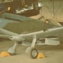
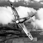
 I had a lot of trouble at home one weekend and out of frustration I curled up at home and retreated to my model building corner. It's quiet at home, which I can't stand at all, so I turn on the TV and listen to MTV: 80's hits To get back down, I opened the cupboard and looked to see which model should be in... then I found my already prepared project Spitfire Type 389 and Type 390... now I won't let you die ignorant. This is about the P.R.XIX, of which there were/are two versions. Since I have two kits of it, it was clear that both versions should be built. First of all, I decided on the lesser-known version, Type 389. How is this different? Sure - in the engine or compressor system. Unfortunately, some people on the Internet don't know for sure what type is, so you have to take a closer look! This is it, the Supermarine Type 389 / Spitfire Mk XIX (Early), two cameras in the fuselage directed on gull wing area downwards, one camera on the left side behind the cockpit, fishtail exhaust pipes (unfortunately I don't have it yet: QB 48191) Literature on this type can only be found in the following editions: KAGERO SPitfire #40 The model from Airfix was easy to build, little rework, the parts fit very well. A good recommendation for all Spitfire fans.
- 9 replies
-
- 5
-
-
- spitfire PR.XIX
- Type 389
- (and 1 more)
-
Airfix is to release in 2014 a new tool 1/72nd Supermarine Swift FR.5 kit ref. A04003 I'm really really disappointed by the scale... So not for me. Source: http://www.airfix.com/shop/new-for-2014/172-scale-military-aircraft/a04003-supermarine-swift-172/ V.P
-
Another build from me, and a switch back to Civil Aviation for this one. This is the Airfix boxing of the Boeing 727 kit and a quick check of the measurements indicate that it scales out to around those for -100 short body version and I will be using a set of 26 Decals for this classic Lufthansa Scheme. Here is an image from Airliners.net of D-ABIB at Stockholm -Arlanda in August 1964. Boeing 727-30 D-ABIB 18360 Box and contents photos. by John L, on Flickr The fuselage parts have some slight warping but should pull together OK. by John L, on Flickr The wing parts will need a bit of tidying to remove a bit of flash. by John L, on Flickr Here are the remaining parts including a stand, obviously issued when these came as a standard item in Airfix kits. by John L, on Flickr And finally my choice of decals for this build. by John L, on Flickr by John L, on Flickr Hope to get started on this soon. John
- 14 replies
-
- 18
-
-
Release expected in Spring (April) 2024 - ref. A05141 - Bristol Bulldog Mk.II https://uk.airfix.com/products/bristol-bulldog-mkii-a05141 V.P.
- 180 replies
-
- 29
-
-
-
de Havilland Tiger Moth (A04104A) 1:48 Airfix The de Havilland Tiger Moth was one of the most important and widely produced trainer aircraft to have seen service with the RAF. It was designed by Geoffrey de Havilland himself in the 1930s and was based on the Gypsy Moth, suitably redesigned to meet Air Ministry Specification 13/31. In comparison to its predecessor, the Tiger Moth's wings were swept and repositioned, and the cockpits were redesigned to make escape easier. The airframe was also strengthened and the engine exhaust system was redesigned. The Tiger Moth entered service with the RAF in 1932 and remained in use until well after the war. Over 8,000 examples were completed, and the type also served with the Royal Australian Air Force, the Royal Canadian Air Force and the Royal New Zealand Air Force as well as a great many other military and civilian operators. In service it proved itself to be ideally suited to its role, being easy enough to fly, but challenging enough to weed out the weaker students. It was also cheap and easy to maintain. Further variants would be the DH.82C fitted with an enclosed hood for cold weather operations in Canada, and the Queen Bee, which was an unmanned radio-controlled target drone that resulted in a thinning of the herd of surviving airframes. Always popular with civilian users, many Tiger Moths found their way into private ownership after the War, with many maintained in flying condition to this day. The Kit This is a reboxing with new decals of the 2019 tooling that made many quarter-scale modellers very happy. We didn’t get chance to review the original release, so it’s good to finally see one in the photo booth. The kit arrives in a suitably sized red-themed top-opening box with some dramatic artwork on the top, depicting the last landing of a biplane on a British Carrier in 1964, which involved HMS Eagle and an airframe from Britannia Royal Naval College in Plymouth wearing a silver dope and dayglo striped scheme, as shown here. Inside the box are three sprues of dark grey styrene, a small clear sprue, decal sheet and the instruction booklet that is printed in colour on matt paper, with painting and decaling profiles on the rear pages, plus a comprehensive rigging guide that extends to two pages of the booklet. Detail is as we’ve come to expect from Airfix, including restrained scalloping of the fabric surfaces, detailed cockpit and even an engine details inside the nose with the option to open one side of the cowling, and the afore mentioned rigging diagram should go a long way to calm any modellers that are rigging-phobic. Construction begins with the cockpit floor, fitting the rear seat and bulkhead, then making up the front seat and its bulkhead, which is a strange shape due to the seat being half-buried in the bulkhead, giving both crew a control column before it is inserted into the port fuselage after doing some detail painting, ensuring that a tab on the front of the floor fully latches in a slot moulded into the firewall in the fuselage halves. A set of rods are inserted into the half engine moulded into the port fuselage, with a scrap diagram showing it from the front, then the two instrument panels with their dial decals are painted and installed in front of each crew member, again after detail painting. The starboard fuselage side has a pair of crew doors moulded into it, but with the perimeters thinned to ease cutting them out if you wish to open them, although you don’t need to retain the cut-out doors, as extra parts are included on the sprues. Engine detail is glued to the flat side of the engine moulded into the fuselage half, and if you plan to use an Airfix stand, there are two flashed-over holes under the cockpit that you can cut out, painting the sidewall detail before you close the fuselage halves and deal with the seams. A curved fairing is fitted to a depression in the port side of the fuselage behind the engine, and on the starboard side the exhaust is attached to the engine, then after drilling a 0.4mm hole in the firewall, the A-frame engine mount is fitted over the engine details after painting and weathering them according to your taste. A top cowling panel is mounted over the top of the motor, fixing the front cowling with intake port and prop fairing, fitting the lower and port engine cowlings in the closed position, then deciding whether to open the starboard cowling to expose the engine detail, or closing it using the same part, a scrap diagram showing its opening angle. A jig is found on sprue C, and is mounted over the tail without glue, which allows you to remove a shallow section of the fuselage top to accommodate the strakes added to the elevators of decal option A. The instructions show it from two angles to assist you, and a file icon suggests what to use to remove this area. After you are happy with the job you’ve done removing the plastic, the elevators with strakes are glued in place for option A, and a different part without strakes is used for option B. Both tail styles are supported by diagonal struts that pin at both ends, plugging the rudder into the rear of the fuselage and adding a tail skid with the aid of a scrap diagram nearby that shows the assembly from another angle. The lower wings are moulded as a single part that is linked by a narrow section that slots into a groove in the fuselage underside. Once the glue is cured, cabane struts are mounted vertically on the curved fuselage sides, preparing the upper wing by adding a ribbed fuel tank on the centre section, then flipping it over to slot the interplane struts into grooves moulded into the wing surfaces. You might wish to align the upper wing with the model while the glue cures, and once everything is set, the two wings can be glued together, ignoring the rigging aspect of this model for the time-being. A scrap diagram shows how the cabane struts fit into grooves in the underside of the upper wing, either side of the fuel tank. The instructions suggest you apply the underwing codes before fitting the aileron actuators that are mounted under the wings, although the decals stop short of interfering with these parts on the diagram, then a handle-shaped part is fixed on the fuselage underside between the wings. The landing gear is created from a bridged W-shaped main strut, which is braced by a pair of diagonal forward struts, one on each side, adding another smaller pair behind the legs while slotting the single-part wheels onto the axles. Turning the model over onto its wheels for the first time, a vent is added to the fuel tank, and a choice of two prop styles are pinned to the front of the model by a separate part, which can be left mobile if you are careful with the glue. Returning to the cockpit, padded coamings are fitted to the front of the cockpit openings, adding faceted windscreens to slots in the top of the fuselage, then if you have cut out the crew doors, two new door parts are installed in the open position, leaving ‘just’ the rigging left to do. Most biplane modellers have their own preferred method for rigging their models, and here Airfix have provided two pages of diagrams to assist with the process, which would be most useful for anyone not familiar with the task. The Tiger Moth isn’t overly complex in its rigging either, so if anyone was thinking of joining the biplane community, this could be a good kit to start your journey with. Markings There are two decal options included on the sheet, with suitably different markings and schemes to broaden its appeal. From the box you can build one of the following: BB852/E, Britannia Flight, Britannia Royal Naval College, Roborough, Plymouth, Devon, 1st July 1965, the last biplane to land on a British carrier (HMS Eagle) No.9 Elementary and Reserve Flying Training School, RAF Ansty, Warwickshire, England, October 1940 Please note that the Dayglo Orange decals above appeared light pink after scanning, so the colour has been approximated by eye and reference to a photo taken on an iPhone in PhotoShop Decals are by Cartograf, which is a guarantee of good registration, sharpness and colour density, with a thin matt carrier film on the dayglo orange decals, and gloss carrier film everywhere else, cut close to the printed areas. Conclusion A welcome re-release for those that didn’t manage to pick the kit up first time around, or just wanted another kit, while the new decals add extra interest, especially the last biplane to land on a British carrier, which will be a bright model thanks to the dayglo stripes, which aren’t pink on the sheet, I promise. Highly recommended. Review sample courtesy of
-
I recently purchased this kit second hand. Unfortunately on opening the box, there were no instructions or decals. However, I managed to download the instructions from Scalemates. I then contacted Airfix to see if they could provide me with the decals. After a couple of days, I received a reply asking for my address and telephone number "to help speed up the enquiry". That was on 9th February. To date, I have had no further communication from them (I emailed them a couple of days ago, but nothing). If, for some reason, they cannot provide the decals, does anyone know where I can purchase decals for the kit? I do have a load of spare decals from other kits, so could probably find a few basic decals, but would prefer to have the whole set. Thanks in advance.
-
My Meteor is going okay so, in a burst of enthusiasm and ignoring all the nearly finished kits littering my workdesk, I've started another kit. I've had this one in the stash for years, not entirely sure why because I don't make Axis stuff. Anyway, I'm going to avoid my no-Axis rule and make it as a Bf-110 C-5. I took a photo of the sprues... But promptly forgot to take any more photos until I'll try to take more photos as the build progresses.
- 27 replies
-
- 21
-
-
Joining you with this kit, costing £3 at Lyneham last year. Which carried stripes after D-Day. Which is how I intend to complete the build.
- 23 replies
-
- 11
-
-
I think I am starting to become a Meteor buff! Hot on the heels of the SH Meteor F.8 in SyAAF scheme, I started building the Airfix kit. I did not chose one of the schemes proposed in the box but an IAF scheme from the SH Kit: This is a good occasion to compare both kits and, spoiler alert, the Airfix kit is much much better! It is really well designed, the detail is excellent, the fit is top not notch and the moulding quality excellent. The cockpit tub is a 3 part assembly and has the characteristic horseshoe shape that its SH counterpart does not have: It is really easy to position it accurately inside the fuselage: Clever engineering. The seat is decent OOB but misses the harness and can benefit from a few added details: The fuel tanks have the rim that is missing on the SH F.8 and are more correct in shape. Note: the fuel tanks on the SH NF.14 are OK too. The engine heads are more detailed than on the SH F.8 but the SH NF.14 reactor heads are better. The IP, nose wheel leg and cockpit quarterdeck (is that correct?) have better detail: The air inlets in one part are a very good idea: No need to deal with an awkward seam between top and bottom half like on the SH kit. The engineering of the main landing gear bay walls is also really clever: 4 parts, a mortise-tenon system and you're done! The main landing gear bay roof only needs a black wash over the alu paint to make the details pop: I assembled the wings and painted the air inlet lips in black and white: The result can seem weird but the period pictures show they were actually painted this way on the original airframe. The flaps are provided as separate items but I always saw them level on the pictures. So, not really useful IMHO. I also painted the nose in black and white: But I have to re-paint it as I inverted the black and white areas! Doh! The main landing gear legs and wheels are the only letdown on this kit: Two gear leg halves and two wheels halves that have to be glued together. Filler is needed to get something clean. But that is only a minor gripe. So far, this is a fantastic kit and a real pleasure to build.
- 24 replies
-
- 13
-
-
Fairey Rotodyne (A04002V) 1:72 Airfix Vintage Classics The Fairey Rotodyne was an ambitious project in the post WWII heyday of British aviation, when the aviation world could re-concentrate their efforts on more radical designs, which included the development of rotary-winged flight types that had been of interest during the 30s, but was put on the back-burner during WWII to concentrate on more pressing matters. Fairey were interested in creating a combined rotorcraft that merged autogyro with helicopter, using both type’s strengths to provide a cheaper, faster method of transport that could take-off and land vertically without the high expense associated with helicopter flight then and now. Fairey envisaged blade-tip engines powering the rotors, thereby obviating the need for a stabilising tail rotor, while the rotor would transition to autogyro mode once horizontal flight was achieved, powering down the engines and utilising the passive lift generated from the blades along with the short wings carrying a pair of turbo-prop engines that would supply forward momentum, but could also be used to counter any torque encountered during flight. The engines also supplied high-pressure air to the blade-tip engines, mixing it with fuel and burning it to provide energy to the blades to rotate. Fairey already had experience with this type of flight with their Gyrodyne, which had been demonstrated to be effective, although its size and fuel capacity limited its range substantially. It acted as a development precursor that gave Fairey confidence in its design, although the form factor and layout changed from several times during development before they settled for the twin-engined design. Which brand and type of engine became a problem however, as Fairey had their preferences, and many leading engine manufacturers considered themselves already over-stretched with various projects. Politics reared its ugly and divisive head, as the British Government had been bankrolling the project on the basis that it could be useful for military applications, and in the hope that airline BEA would make an order for at least 20 airframes to act as financial backstop for the project, which they blew hot and cold on as time went by. During the greater periods of interest, there were plans to build an enlarged variant of the Rotodyne that could carry up to 70 passengers, which would have resulted in an even more cost-effective return than the already reduced cost of the original design. The choice and power output of the engines was an ongoing issue that helped to kill the project, along with concerns over the noise caused by the rapidly spinning blade-tip engines, which were said to be painful and potentially damaging to hearing close-up, and still a nuisance even at greater distances, making conversations within range a difficult prospect. There were attempts to reduce this to a more acceptable level, and progress was beginning to be made as funding was withdrawn in the early 60s, leading to the project’s cancellation when Fairey’s new owners, Westland were likely to have to foot the bill for the completion of development. There was a good chance that the noise could have been brought down to similar or lower levels than other vehicles that were in use at the time, but it was never to happen, as the curtain was brought down on a promising project. The Kit This is a reboxing of Airfix’s vintage tooling, which was first released in 1959 while the Rotodyne was still in development, so as you’d imagine it’s a product of its time, and expectations should be measured accordingly. It is however eminently possible to create a realistic and well-detailed model from the kit, as our membership have proved in the past if you’d care to search the forum’s sub-sections. The kit arrives in a modestly sized top-opening box, and inside are eight borderless sprues in a dark grey styrene, a clear sprue, a sheet of decals, and the instruction booklet that is printed in colour on matt paper, with profiles for painting and decaling on the rear inner cover. As already mentioned, this is an old kit and should be viewed through rose-tinted glasses, as it’s even older than most of us on the forum. Considering its age, time has been kind to the moulds, with surprisingly little flash, and virtually no mould damage other than some scratches evident on the upper rotor-head and one of the tail parts at first glance. It was tooled during Airfix’s heavy riveting period, covering the skin of the kit in thousands of fine raised rivets that can be obliterated during seam filling. Construction begins with the cockpit, which is a simple floor with a moulded-in centre console with decal, and two turrets that the seats plug into, with a crew member for each seat, although they have their hands by their sides so won’t be doing much controlling of their charge unless you plan on undertaking some surgery. The cockpit is enhanced with a pair of thick control columns, and in front of the crew is an instrument panel for which a new decal has been provided, with realistic-looking dials on a grey background that look rather nice. The bulkhead behind the crew has a door moulded-in, and the nose gear leg with twin wheels is fixed to the bottom of this, putting the assembly aside while you prepare the two fuselage halves with ten oval portholes on each side, even though there is no interior present in the passenger cabin. This was the norm back in the day though, so you can either paint the interior a black shade, or build yourself a simple floor and add some seats. To close the fuselage, you will need to create the rotor-head, which consists of top and bottom halves, with a dome added to the top, and a shaft/pin inserted into the hole underneath. This and the cockpit are trapped between the two fuselage halves, taking care not to allow the glue to seep into the socket for the rotor if you wish it to remain mobile later. Seam-filling will doubtless remove some of the raised rivets on the surface, so you may wish to toy with the idea of either removing them all, converting the model to recessed rivets, or picking up some suitably pitched printed 3D rivet decals to replace those lost in the seam-filling process. The same will be true for the other external surfaces, so take it as read that this will occur for those parts of the model. The Rotodyne’s wings are simple top and bottom halves, painting a small portion of the underside interior silver because it will show through a hole in the upper wing. These are put to one side while the tail is made, creating the horizontal section from two parts plus a single flying surface that can be left mobile by not gluing them in, then adding the upper portion of the fin in two halves, and the lower portion that has a separate rudder panel, building one for each side of the model, and plugging them into the sides of the fuselage along with the wings and the surprisingly clear canopy part at the front. The two engine nacelles are split vertically in half, and are equipped with a nose with intake, through which the prop’s axle slots, securing the four-bladed propeller in position. Intakes and exhausts are added to the sides, and the main gear legs are trapped between the two nacelle halves during closure, fixing a pair of wheels to the ends of the axles. Once complete, they are pinned to the underside of the wings, and the main gear bays are given three doors each, plus another three for the nose gear leg that is now projecting from the bay under the nose. One useful feature of the Rotodyne was the clamshell rear doors that made loading cargo an easy task. These are supplied as two curved sections with four-part hinges that let them open and close if you are careful with the glue. They are locked into position by a pair of C-shaped clamps that glue to the interior of the fuselage in the tail. The penultimate task is to build the rotors themselves, adding half of the tip motors to the ends, and plugging each blade root into the rotor-head, ensuring they are installed at the same angle of attack for accuracy’s sake. The forward access door in the port side of the nose is depicted in the open position, hinging up and down in two halves, with a stairway glued to the lower portion for easy access. Markings There was only one flying Rotodyne, and it wore a fetching white, blue and silver scheme, with Fairey Rotodyne written in large text over the lower silver areas on the sides. From the box you can build the following: Decals are by Cartograf, which is a guarantee of good registration, sharpness and colour density, with a thin gloss carrier film cut close to the printed areas. Conclusion There is only one kit in this scale, and this is it. It’s an old kit, but it gets the basic shape, and despite some of the details being a little toy-like, a creditable replica can be made with a little effort. The inclusion of new decals will certainly help with that, as they are very crisply designed and printed, especially the instrument panels. Highly recommended for a vintage kit. Review sample courtesy of