Search the Community
Showing results for tags '1:350'.
-
It's been quite a while since I've built a model, mainly due to chronic back pain and depression. But having reviewed this kit HERE, I felt a spark of interest, so today I've broken the tools and paints out and sorted out the modelling table ready to go. I also thought I'd do a WIP and build review while I'm at it. Gratuitous box shot.
- 30 replies
-
- 6
-

-
- Tsesarevich
- 1:350
- (and 1 more)
-
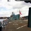 This is my Type 42 Destroyer Model I brought and due for a Major refit to strip her into later HMS Newcastle 2004 era from earlier T42, 1970s - 80s, is about 41cm x 5cm EDIT: More Photos: 45cm Ruler in 1st photo.
 -
USS Yorktown Eduard 1:350 It was great to see Merit International release the USS Yorktown earlier this year, but, no matter how great a kit is, Eduard always seem to find something to improve upon. The first two sets for the Yorktown have now been released. The first is for the ships boats and cranes, whilst the second is for the AA weaponry. Both sets are up to the usual standard set by Eduard and as such are full of very small parts, where a good pick-up pencil wouldn’t go amiss. Some of the kit parts need to be modified by the modeller before the etched parts can be fitted. Ships Boats and Cranes, (53140). This two sheet set contains parts for all the ships boats, the two large cranes either side of the aft hanger plus the jib for the main deck mounted crane. Each of the enclosed motor boats is provided with new centre cockpits, complete with the boats wheel, as well as a new prop, rudder, front and rear cabin doors, plus a full boat load of handrails and railings. The open motor cutters are fitted with new thwarts/gunwhales, deck planking, cockpit, engine housing, propeller, rudder, flag staff, bow mounted windlass and rear mounted railings. The larger of the motor cutters also has a fo’c’sle mounted anchor. Each of the carley floats is given a new grating, for which the centre of the floats will need to be carefully removed, and selection of straps and fixings tying them to the ship. The large cranes mounted either side of the rear hanger are completely replaced with new brass ones. Once folded to shape they are each fitted with the two hooks and their cable wheels, rotating base, through which a small piece of styrene rod is mounted. The large platforms atop each crane are provided as they are missing on the kit cranes. The deck mounted crane jib is a complex affair, comprising a three sided box section into which seven ribs are fitted before the missing side of the jib is attached. The jib is then fitted with the two hooks, their cable wheels and finished off with the handrail that is fitted to the top. Whilst the trunk of the crane isn’t replaced, it is detailed with the prominent vertical ladder, top platform, complete with railings, mid section walkway and the associated platform supports. AA Guns, (53141). As the title suggest, this single sheet set is to provide detail for the various AA weaponry found around the ship. The 5” single mounts are fitted with new sights and railings, whilst their mountings receive new three part bases and two ready use lockers for each of the eight guns. The quad 1.1” mounts also receive new sights, sight mount, shields and their supports and gun top plate. Their mountings also receive new bases, but these are single piece items. The twenty four 20mm Oerlikons are each fitted with new shields, shield supports; sights, shoulder harness and ammunition drum face. Conclusion You either love or hate brass etched detail sets, but for me they are almost vital, if you wish to produce as detailed a model as possible. Eduard are pretty much the kings of mainstream maritime etch at the moment and their release schedule seems inexhaustible. These sets will certainly go toward building that museum quality model that we all strive for at one point or another. Who knows how many more sets they will produce for the Yorktown, but I know for sure these won’t be the last. Very highly recommended. Review sample courtesy of
-
- 2
-
-
- USS Yorktown
- 1:350
- (and 2 more)
-
Russian Navy Battleship Tsesarevich 1904 Trumpeter 1:350 History Tsesarevich was a pre-dreadnought battleship of the Imperial Russian Navy, built in France at the end of the 19th century. The ship's design formed the basis of the Russian-built Borodino-class battleships. She was based at Port Arthur, Manchuria after entering service and fought in the Russo-Japanese War of 1904–05. Tsesarevich was the flagship of Admiral Wilgelm Vitgeft in the Battle of the Yellow Sea and was interned in Tsingtau after the battle. At the end of the Russo-Japanese war, the ship was transferred to the Baltic in early 1906 and helped to suppress the Sveaborg Rebellion later that year. Around 1906, her fighting top was removed and her superstructure was cut down. The 75 mm guns in the superstructure were apparently removed as well. Tsesarevich made regular winter cruises to the Mediterranean before World War I and aided survivors of the Messina earthquake in December 1908. In 1909–10 the ship's machinery was overhauled and her amidships casemated 75 mm guns were removed and plated over four years later. Tsesarevich was not very active during the early part of World War I and she reportedly received two 37 mm anti-aircraft guns during the war. Because of her inactivity her bored sailors joined the general mutiny of the Baltic Fleet in early 1917. She was renamed Grazhdanin on 13 April 1917 after the February Revolution. The ship took part in the Battle of Moon Sound in October 1917. During the climatic part of the battle, Grazhdanin engaged the German minesweepers on 17 October with little effect while Slava engaged the German dreadnoughts König and Kronprinz. The latter fired at Grazhdanin and hit her twice, killing one and wounding four crewmen, although neither hit caused significant damage. The German dreadnoughts outranged Grazhdanin and she was forced to retreat and abandon Moon Sound in the face of German pressure. By December the ship was in Kronstadt where she came under the control of the Bolsheviks and she was hulked there in May 1918. Grazhdanin was scrapped beginning in 1924, although she was not officially stricken from the Navy List until 21 November 1925 The ship was ordered as part of the "Programme for the Needs of the Far East", authorised by Tsar Nicholas II in 1898 to defend Russia's newly acquired ice-free port of Port Arthur in Manchuria. Russian shipyards were already at full capacity so the Naval Ministry decided to order ships from abroad. Specifications were issued on 14 June 1898 and a few days later the chief designer of the French shipyard Forges et Chantiers de la Méditerranée proposed a design based on that of the French battleship Jauréguiberry. The Naval Technical Committee approved the design with a few changes to which the French readily agreed. The General Admiral, Grand Duke Alexei Alexandrovich selected the French design over a competing proposal from the Baltic Works. A contract was signed on 20 July 1898 at a cost of 30.28 million francs (11.355 million rubles) for delivery in 42 months. Tsesarevich 's most obvious design feature was her tumblehome hull. This had several advantages because it allowed greater freeboard since the narrow upper decks reduced the structural weight of the vessel's hull, it increased the field of fire of guns mounted on the sides, and it reduced the ship's roll in heavy seas. Its great disadvantage was that it reduced buoyancy and stability which contributed to excessive heel during turns. During the Battle of the Yellow Sea in August 1904, Imperial Japanese Navy observers thought the Tsesarevich was going to capsize when she suddenly turned out of the battleline. Tsesarevich was 118.5 metres (388 ft 9 in) long overall, had a beam of 23.2 metres (76 ft 1 in) and a draught of 7.92 metres (26 ft 0 in). The ship displaced 13,105 tonnes (12,898 long tons). Her crew consisted of 28–29 officers and 750 enlisted men. The Model Having released the Tsesarevich in her 1917 guise last year, Trumpeter have now released a kit of her as she was when first completed. The kit comes a top opening box with a very nice artists impression of the ship, anchored at the head of the battle line. On opening, the modeller is confronted with the two hull halves, whose bow and stern sections are given extra foam protection, eight sprues of medium grey styrene, three sub-sprues, five sheets of etched brass, a length of brass chain and a small decal sheet. The sprues are clear of flash and other imperfections and there are fewer moulding pips than normally found on Trumpeters ship kits. The moulded on detail is very nicely done and it appears that the unusual tumblehome shape of the hull has been moulded with all the right curves, although as I don’t have any plans I can’t tell if it’s totally correct, but it certainly looks the part. With the amount of etch contained in the kit it really can be made straight out of the box without the need of any additional aftermarket sets, although this probably won’t deter the aftermarket companies from releasing them. Before construction proper can begin, the modeller needs to open up quite a few holes, both on the hull sides and the main decks. These are clearly marked in the instructions and on the parts themselves where the holes have been flashed over. The build begins with the construction of several sub-assemblies. These include the six secondary turrets, each made up of the two barrels which are slid unglued onto the trunnion which in turn is glued to the trunnion pivots which are glued to the turret base. The turret itself is then slid over the barrels and glued to the base before being finished off with the addition of a PE rail on the turret roof. The two main turrets are constructed in a similar fashion, but without a roof rail. Next up are the eleven maxim machine guns, made from two styrene parts, (the gun and shield), along with the PE base folded to shape. The six single 75mm guns are all styrene, and consist of the barrel, shield, swivel mount and base, whilst the twelve 47mm cannon come as a single piece barrel/mount requiring only the shield to be fitted. The modeller then has to assemble four cable reels, each with PE stands, PE drum ends and styrene drum, along with six two piece deck mounted bitts. There are another twelve 75mm guns in casemates along the hull and these are glued to three internal bases per side and slid through their firing ports from the inside. With these fitted the hull halves are joined together with the rudder sandwiched between the halves, along with two sturdy bulkheads. The side mounts for the twin 6” secondary turrets are fitted, one per side, near the top of the hull sides. The quarterdeck and bilge keels are also glued into their respective positions. The main deck is the attached along with the quarterdeck/main deck bulkhead, followed by the upper side pieces and lower bridge wings. The large windlass, made up of eight styrene and four PE parts is assembled and positioned at the rear of the foredeck. From the bow, the foredeck is then fitted out with the jack staff, cleats, bitts, ventilators and the splinter shields for the port and starboard 6” turrets. Moving admidships there are three deckhouses fitted, the front one being the base of the bridge. Before attaching the next level of the bridge structure, six supports and the base of the foremast need to be glued into position. With these in place the bridge piece, which has been fitted with the armoured control tower to the underside, can be slid over the mast section and glued into position, followed by the two 6” turrets and two capstains. The bridge is slowly built up with the upper section of the tower, the bridge itself and a further deck with additional deckhouses and deck supports. Four of the 75mm guns are fitted two per side, just aft of the bridge. One deck up an there is a complicated bit of bending required to fit the railing, which you will need to be careful not to knock off as you fit the six 47mm guns, binnacle and rangefinder to the deck. Moving aft the fore-funnel is assembled from two halves and fitted with two PE blocks to the rear, a PE vertical ladder for each side, plus a PE funnel cap, the completed funnel is then fitted to its position just aft of the bridge structure along with a pair of PE inclined ladders. Meanwhile back to the foredeck, and the fitting of the four anchors, plus a pair of booms, one port and one starboard between each pair of anchors. The foretop is then assembled with the main styrene part being fitted with PE angled supports on the underside, whilst on the topside four 47mm guns are fitted, along with PE window frames fore and after and finished off with the roof. This assembly is then attached to the top of the lower foremast section. Between the funnels there are two boat cradle decks, each made up of both styrene and PE parts and glued into their respective positions, one aft of the fore-funnel and one foreward of the aft funnel. On the foretop roof there is a small gun station fitted out with three maxim machine guns with another section of foremast glued to the centre. Just aft of the rear funnel there is another winch unit, this one made up of seven parts. The front main 12” turret can now be fitted along with the two side mounted 6” turrets, whilst the foremast is fitted off with anotehr platform on which another section of mast is fitted along with a searchlight. The previously attached boat decks are fitted with PE cradles onto which the four large cutters are mounted, each cutter also having a two piece whale boat cradled on their thwarts. The aft boat deck is for the steam launches, with each of the four launches, two large and two smaller are each made up of the hull, deck, funnel, gun mount, gun, searchlight, ventilators and propeller, with the smaller ones also having a rear mounted maxim and a torpedo. With the boats fitted the rear funnel can be assembled, this consists of two funnel halves, PE vertical ladders, PE blocks, PE funnel cap and a PE derrick complete with hook. The completed funnel is then glued into position. At the centre of the foreward boat deck there is a searchlight tower made from a PE tower structure, PE railings, PE ladder and styrene searchlight. The aft superstructure supports are attached, along with the aft pair of 6” turrets, the aft mounted main 12” turret along with two decklights, inclined ladders, aft mounted anchor, spare anchor just aft of the rear boat deck, a pair of derricks each side, the boat booms, bitts, cleats and ensign staff. The after superstructure deck is fitted with a deckhouse and angled supports glued to the underside, before being fitted onto the previously attached supports between the two aft 6” turrets. The four piece steam launch derrick is assembled and fitted to the rear of the aft superstructure deck along with another deckhouse and further deck supports, onto which another deck is fitted. This upper deck is fitted with six 47mm guns and another complex railing which will require careful bending to shape. Both the foremast and mainmast are finished off with the addition of the mast tops and various length yards and platforms along with each having a pair of searchlights fitted. The foreward boat deck is then fitted with a pair of large davits complete with PE downfalls, whilst the two convoluted, (to cope with the weird tumblehome shape of the hull), PE accommodation ladders are assembled and glued one per side aft of the steam launch deck. Another pair of whale boats are attached to the derricks previously fitted to the ships sides. To finish the kit of it’s only a matter of fitting the two propeller shafts, propellers and assembling the stand supplied, complete with a nice plaque with the ships name on. Decals The small decal sheet contains two sizes of ships crest, the Russian and Ensign, in both flat and wavey form. For what it is, it is very nicely printed, although the blue cross on the wavey ensign appears to be quite a bit out of register. Conclusion I just love the look of these ships in which you can clearly see the French influences. They look so wrong that they’re right, if you know what I mean. This is a very interesting kit and will make a nice, different addition to any maritime collection. Without any plans I cannot say definitively how accurate it is, but it looks pretty good when compared with the published photographs, although the kit seems to be a little undergunned in the tertiary department as the details show that she actually was armed with a few more 47mm and additional 37mm cannon. Otherwise it is a very nice kit and can recommend it quite highly. Review sample courtesy of UK Distributors for
- 7 replies
-
- 5
-
-
- Pocketbond
- 1:350
- (and 2 more)
-

Uss Indianapolis (CA-35) (Academy 1:350)
PergerCRO posted a topic in Ready for Inspection - Maritime
Yesterday i finished my first ship It is Academy's USS Indianapolis in 1:350 scale. I don't have enough expirience to say is this good model, or not, are details correct and that stuff, but it's my first and I am happy. The stand under the ship is home made with help from family and friends. The pictures are here so please leave comments no matter are they good or bad Thank you.- 8 replies
-
- 6
-
-
- Indianapolis
- Academy
- (and 1 more)
-
HMS Illustrious R-06 Eduard 1:350 The Airfix 1:350 HMS Illustrious kit has been out for some time now, in fact it was first released in 2010. It’s only since the sad demise of White Ensign Models that Eduard have finally decided to release some etch sets for the kit. There are three sets in total providing everything the modeller needs to superdetail their kit. (53136 Superstructure) This two sheet set contains one large sheet and one small one. As the set name suggests this set is purely to add detail to the island superstructure and will make for a very busy and detailed area. Before adding any etch a lot of the moulded kit details have to be removed, so study the instructions carefully, as it’s probably best done before anything else. Apart from all the watertight doors, hatches, vertical ladders the set contains new air intakes, goofer deck railings, otherwise known as 02 deck, and 05 deck railings, along with numerous small fixtures and fittings. The Type1022 radar is all but replaced with PE with only the bottom mounting and IFF aerial kept from the kit part. The funnels receive new yards, complete with their associated aerials, plus the upper hand/foot rails, whilst the main and fore masts are also fitted out with new yards, supports, platforms, complete with railings and aerials. A completely new platform and its supports are fitted just aft of the rear funnel, in fact there appears to be quite a few new platforms contained in this set, each with their supports and railings. The Satcom dishes and several other aerials are replaced with complex etched parts which will need some careful rolling to get the correct shape and there are new bases for most of the other kit aerials and radars. Whilst the individual floodlights from the kit are used, some careful cutting will be required for these; the support frames are completely replaced. Around the Flyco area of the bridge there is some new netting and beneath, the landing light arrays and their support frame are attached. At flight deck level there are seven new hose reels to fold and fit. (53137 Flight Deck) This single large sheet set contains not only lots of detail for the flightdeck, which includes the catwalks but also for other areas. As with the previous set there is quite a bit of kit detail that needs to be removed first, before the etch can be aded. The watertight doors on the quarterdeck and each of the boat deck openings and included, along with the two accommodation ladders, one for each side and all the railings that are pre cut to fit into their respective opening. Along both sides of the ship there are large air intakes and these are replaced with etched parts. On the inboard side of the ski-ramp the set includes a length of netting, two hose reels and three hatches, whilst on the foredeck new closed chocks, and mooring platforms are fitted and a selection of hose reels are fitted in the catwalks. The next bit will require lost of careful cutting out as all the kit catwalks are replaced with the exception of the outer bulkheads. The bulkheads are then fixed to the new perforated etched parts before being attached to the hull and all the angled supports fitted. Lastly the ships crane is provided with new lifting wires, guides, rollers and a hook, whilst the ships boats all have new handrails, guardrails and helm wheel fitted. (53138 Safety Nets). As the name suggests this set contains a full ships worth of safety netting is supplied on the one smallish sheet. Well, everything that wasn’t included in the set above. Conclusion It’s nice to see Eduard finally bringing these sets out as with the loss of WEM modellers were unable to detail their HMS Illustrious kits to the extent that other models could. Now this has been rectified I wonder if we’ll see more models being built and seen on Britmodeller and at shows. Review sample courtesy of
-
- 1
-
-
- HMS
- Illustrious
- (and 2 more)
-
i am looking to buy a Tamiya 1:350 Yamato kit, and found the Tamiya 78025 and 78030 sets. but i need some help to clarify the differences on the sets. i know the 78030 is a premium edition with some photo etch sets. both should be the new retooled sets, but i am not 100% sure. 78030 78025
-
Just been browsing through Steel Navy and there was a rumour about Trumpeter releasing a 1:350 Ark Royal III. I do hope it is true but I am a little sceptical. But being the up standing citizen I am I thought I would spread it further in the vain hope that if it is a load of humbug then hopefully an upsurge in interest may push it closer to fruition. Any hoo to prove I am not just making it all up here is the evidence: https://www.facebook.com/TrumpeterModel/photos/a.103538733138062.8169.103526326472636/473459132812685/?type=1&theater Its got me suckered in
-
Turned replacement barrels 1:350 Master It’s quite amazing the number of sets of turned barrels Master Models have released, and they continue to dominate in the field with the release of these four new packs. Each set comes with a small sheet of instructions informing the modeller how to use the metal barrels and what size holes you need to drill out once the styrene parts have been removed. [350-082] this first set is for the newly released USS New York battleship from Trumpeter. The small packet contains twelve turned aluminium barrels for the main 14” armament, eight turned brass 5” barrels and twelve turned brass 3” barrels. [350-085] This set is for the Trumpeter 1:350 Tsevarevich (1917), and contains four 12” turned aluminium barrels, twelve 6”, two 47mm and two 37mm brass barrels. [350-083] Contains eight 5”, (127mm) turned brass barrels for use on Japanese destroyers whose turrets are not fitted with blast bags. [350-084] Contains eight 5”, (127mm) turned brass barrels for use on Japanese destroyers whose turrets are fitted with blast bags. Conclusion Well, there’s not a lot more to say about these sets, other than if have a requirement to replace you kits barrels then you NEED them. They are so much better than the injection moulded ones can ever be, and will really enhance the finished models. I really would like to see the lathes that these are turned on. Very highly recommended. Review sample courtesy of Piotr at
-
USS Robert E Peary OrangeHobby 1:350 History The 46 ships of the Knox class were the largest, last and most numerous of the US Navy’s second-generation ASW escorts. The lead ship of the class was the USS Knox (FF-1052), laid down October 5, 1965 and commissioned April 12, 1969, at Todd Shipyards in Seattle. Planned as the follow-on to the twin 5-inch gun armed Garcia class frigates and the Tartar missile-equipped Brooke class frigates, their initial design incorporated the prior classes’ pressure-fired boilers (the design later was changed to conventional 1200 psi boilers) in a similar-sized hull designed around the massive bow-mounted AN/SQS-26 sonar. Ten ships were authorized in FY 1964, sixteen in 1965 and ten each for FYs 1966, ’67 and ’68; six were canceled in 1968 and four more in 1969. They were built in four different shipyards and were originally commissioned as destroyer escorts (DEs) 1052–97 in 1969–74, they were redesignated as frigates (FF) on 30 June 1975. The Knox class was the Navy’s last destroyer-type design with a steam powerplant. Due to their unequal comparison to destroyers then in service (large size with low speed and a single screw and 5 inch gun), they became known to a generation of destroyermen as “McNamara’s Folly.” These ships were retired from the US Navy at the end of the Cold War due to a declining need for an advanced ASW capability. By 1994 all ships of this class had been retired from the US Navy, although some remain in service with foreign nations such as Egypt, Taiwan, Thailand, Turkey and Mexico. At 4,200 metric tons (4,130 tons), with a length of 438 feet (133.5 metres) and a beam of 47 feet (14.3 m), they are driven by a single screw geared turbine developing 35,000 shaft horsepower (26 MW), giving them a speed of 27 knots (50 km/h). The steam plant for these ships consists of two Combustion Engineering or Babcock & Wilcox "D" type boilers, each equipped with a high-pressure (supercharger) forced draught air supply system, allowing a plant working pressure of 1,200 PSI and 1000 °F superheat. This design allows fast acceleration, crucial while prosecuting a submarine attack. They are equipped with one 5 in (127 mm) 54 caliber Mark 42 gun forward, an ASROC abaft the gun and forward of the bridge. Since they are single purpose platforms their surface defense capability is nominal; however they do mount Harpoon missiles and Mk-46 torpedoes. The aft weapons point was originally outfitted with Mk 25 basic point defense missile systems (BPDMS) for launching Sea Sparrow missiles. These were eventually refitted with a 20mm Phalanx CIWS. They are equipped with a helicopter hangar aft. USS Robert E. Peary (FF-1073) was the third US Navy warship ship so named and was laid down 20 December 1970 by the Lockheed Ship Building and Drydock Company at Seattle, Washington; launched 26 June 1971; sponsored by Miss Josephine Peary; and commissioned 23 September 1972, Comdr. Charles Beasley, USN, in command. After twenty years of service, and the end of the Cold War she was decommissioned on 7 August 1992, struck from the navy list on 11 November 1995 and transferred to the Republic of China. As of 2005, the destroyer escort serves in the Taiwanese navy as Chi Yang. The Model The kit is contained in a very sturdy cardboard box with a sleeve showing the kits name and other details. With the sleeve removed you are able to open the front opening box which contains ten sprues of bluey grey resin, separate upper and lower hull sections, eight other resin parts, four turned brass parts for the gun barrel and mast tops, plus fourteen tiny, and I mean tiny, turned bitts. The kit also includes eight sheets of relief etched brass and comprehensive decal sheet. As we have come to expect with OrangeHobby the detail on the mouldings is excellent, unfortunately due to the tight packing of the parts a couple of the cleats and the very tip of the bow on the upper hull have broken off. The other item that needs addressing before construction can begin is the large moulding tabs that are attached to the upper and lower hulls on the join line. Not so much of a problem if the kit is built as a waterline model, but if built as a full hull getting a good join will take quite a bit of fettling and filling. Once the parts have been cleaned in warm soapy water, the moulding blocks removed and the parts cleaned up construction can begin. If you’re going to build it full hull then once the upper and lower hull sections have been joined and cleaned up the bulbous bow can be attached, along with the two stabiliser fins, rudder, propshaft, propshaft support bracket and rudder. The etched anchor chain, complete with stoppers is fitted to the fore deck with the rear ends to the two chain pipe openings and the front to the anchor, which needs to be carefully folded to shape. The resin capstan and brass bitts are then fitted into their respective positions, on the fo’c’sle, whilst on the quarterdeck the resin cleats and more brass bitts are attached. These parts could be left off till later as they will make handling the model a little more awkward and be prone to being knocked off. The instructions then call for the modeller to attach the railings between the bridge superstructure and the fo’c’sle side plates and on 01 and 02 decks, this is a bit early to be fitting them in my view and should be left off till near the end of the build. The resin intakes and Super RBOC launchers are fitted to the roof of the superstructure whilst the PE liferaft racks complete with resin liferaft canisters are fitted to each side of the superstructure. The inclined ladders are then folded to shape and attached to their respective positions. The signal flag locker sub assemblies with two styles of inclined ladder and signalmans deck plate. The rear superstructure, which includes the hanger bay is now fitted out with watertight doors, a raised PE platform and supports, rear aerial mast and two whip aerial towers plus a number of vertical ladders, along with resin ventilators. The completed assembly is then fitted to the main deck. Moving forward there is a small foremast fitted just above the bridge consisting of PE supports and light platforms, turned brass mast and PE vertical ladder. Just forward of the bridge on a dedicated PE platform the resin navigation radar antenna is fitted. Just aft of the bridge the Mk67 gun firing control system director complete with AN/SPG-53 fire control radar array is sited, made up from the resin mounting, resin radar dish, and PE dish supports. Amidships there are two PE ECM towers, topped off with two platform sections and the resin AN/SLQ-32 arrays. To the rear of the main superstructure two whip aerial platforms, made up of PE platform, railings and two liferaft cradles then finished off with a PE aerial. The kit comes with a choice of hanger sections, either retracted or extended and these are fitted into the hanger bay of the rear superstructure. Once again the instruction call for the railings and also the flightdeck netting to be fitted, but can be left off till the major parts of the build are completed. The next page of the instructions contains probably the most complicated sub assembly of the whole build. Working around the resin MACK the majority of the parts are PE and include the main mast, X platform, platform supports, walkways, wind baffles, the impressive, but complex AN/SPS-40 Air Search Radar array and the smaller AN/SPS-67 Surface Search array. The two radar arrays are fitted on top of resin towers and the whole assembly is finished with a resin yardarm with PE halyard arm and the resin top mast with PE vertical ladder. The two davits for the ships boats are then assembled; these have to be the most accurate davits I have seen in a 1:350 kit. They come complete with all lowering/raising motors, access platforms and a lovely rendition of the rope ways and blocks. Once complete the boats can be attached and the assemblies glued into position. With the hull complete it’s only a matter of assembling the ships armament which consists of the 5” gun with separate metal barrel, the Mk-16 8 cell missile launcher for ASROC and Harpoon missiles with separate mounting allowing the modeller to pose it in any position they want, and the 20mm Phalanx, which is made up of five resin parts and again can be posed as required. Lastly the single SH-2 Seasprite (LAMPS I) helicopter is assembled from seventeen parts, either resin or PE, these included the fuselage, cockpit and cabin doors, undercarriage, windscreen wipers, tail rotor, rear stabilisers, either extended or folded main rotor blades, main rotor head, MAD bird and it’s support cradle. You then have the choice of mounting the Mk44 torpedo which is itself made up from seven separate parts. Decals The smallish, but comprehensive decal sheet provides all the markings required for such a ship. These include the large flightdeck markings which will need to be placed on a nice gloss base to prevent silvering, ships numbers in two styles for bow and stern, warning circles for the ships weaponry and aerials, RAS station marks, the ships crests, and two sizes of national flag. The decals are well printed and are all in good register, nicely opaque and with a nice thin carrier film. Conclusion This is certainly one very nice kit, loaded with detail and some beautiful moulding. Yes, it won’t be the easiest kit to build, even when compared with some other resin releases, but it will be so worth the effort. This is definitely not one for the beginner or even an intermediate modeller with limited resin experience, without a large dose of patience, care and a very steady hand. But I can quite happily recommend this kit very highly if you have those qualities. Review sample courtesy of Orange Hobby.com
-
USS George Washington Mikro Mir 1:350 USS George Washington (SSBN-598), the lead ship of her class of nuclear ballistic missile submarines, was the third United States Navy ship of the name, in honour of George Washington (17321799), first President of the United States, and the first of that name to be purpose-built as a warship. The boats keel was laid down at Electric Boat Division of General Dynamics, Groton, Connecticut on 1 November 1957. The first of her class, she was launched on 9 June 1959 sponsored by Mrs. Robert B. Anderson, and commissioned on 30 December 1959 as SSBN-598 with Commander James B. Osborn in command of the Blue crew and Commander John L. From Jr. in command of the Gold crew. George Washington was originally laid down as the attack submarine USS Scorpion (SSN-589). During construction, she was lengthened by the insertion of a 130 ft (40 m)-long ballistic missile section and renamed George Washington; another submarine under construction at the time received the original name and hull number. Inside her forward escape hatch, a plaque remained bearing her original name. Because the ballistic missile compartment design of George Washington would be reused in later ship classes, the section inserted into George Washington was designed with a deeper test depth rating than the rest of the submarine. The USS George Washington left Groton on 28 June 1960 for Cape Canaveral, Florida, where she loaded two Polaris missiles. Standing out into the Atlantic Missile Test Range with Rear Admiral William Raborn, head of the Polaris submarine development program, on board as an observer, she successfully conducted the first Polaris missile launch from a submerged submarine on 20 July 1960. In 1982, she returned to Pearl Harbor from her last missile patrol. In 1983, her missiles were unloaded at Bangor, Washington to comply with the SALT I treaty. She had made 55 deterrent patrols in both the Atlantic and Pacific oceans in her 25-year career. George Washington continued service as an attack submarine (SSN), returning briefly to Pearl Harbor. In 1983, she departed Pearl Harbor for the last time and transited the Panama Canal back to the Atlantic and to New London. She was decommissioned on 24 January 1985, stricken from the Naval Vessel Registry on 30 April 1986, and scheduled for disposal through the Ship-Submarine Recycling Program at Puget Sound Naval Shipyard. Recycling of the ship was completed on 30 September 1998. The Model Although kits of the USS George Washington have been released in the past, this is the first in the popular 1:350 scale, which is great news for those of us who model in this scale. At last we can have a model of this iconic vessel in out collection. The kit comes in the familiar coloured top opening box, inside of which the kit parts are safely held in a poly bag. Considering the size of the completed model, there are very few parts, making it a great kit to start with if you thinking of making a selection of submarine models. The grey styrene is not as soft as some short run kits Ive come across and the moulded details, such as the silo doors, are very nicely moulded. The two hull halves are cut vertically rather than the standard horizontal seen in most other kits. This makes the modelling of a waterline diorama so much easier. If making the model as full hull the two halves are glued together and the join line filled and sanded as necessary. The single piece silo section is then glued to the upper hull, followed by the five part sail assembly, consisting of two sail halves, sail top and two dive planes, being attached to the forward end of the silo section. The sail is provided with two periscopes which are fitted to the top of the sail. The upper and lower rudders and the aft dive planes are then attached to the rear of the hull, followed by the etched propeller, with a choice of early or late styles and propeller boss. With the boss the in place, the blades must be twisted carefully to shape, which is shown in the instructions, but you might get better results by finding a photograph of them on the internet or your library. Decals The small decal sheet provides the boats ID number, fitted to the fin, its name plate, fitted to the aft section of the missile silos, depth markings and escape hatch markings. The decals look suitable opaque and in register with very little in the way of carrier film. But still best use on a glossy base. Conclusion This is another superb kit from Mikro Mir, and a great addition to any collection. Due to the nature of the real submarines shape it is naturally a very simple kit, which will be good for even the most novice modeller. Yet its still able to be built by the expert modeller who can take that extra time with the painting and more importantly the weathering. Highly recommended Review sample courtesy of
-
Project 641 Foxtrot Class Submarine Mikro Mir 1:350 To replace the first post-war oceanic submarines of Project 611 in the late 1950s in the CDB-18, a new project, designated 641. The chief designer of the project was S. Egorov, then this post he held from 1958 Z. Deribin with 1974 N. Kormilitsin. Project 641 was intended for the same tasks as the project 611: fighting for further communication, minelaying, reconnaissance, anti-submarine action. Compared with the previous project 611 project 641 boats had more autonomy and cruising range, greater depth of immersion, improved weapons and improved living conditions of the crew. The project was considered successful. It was built 75 ships, including 17 for export to the Polish Navy, India, Libya and Cuba. Four boats of the project (B-4, B-36, B-59 and B-130) participated in Operation "Kama" (attempt to break Cuba is in a state of blockade) during the Cuban missile crisis. In 1997, the division of Soviet Black Sea Fleet between Russia and Ukraine Boat Project 641 B-435 was transferred to Ukraine and was named U01 «Zaporizhzhia". The boat was built in Leningrad Novoadmiralteyskom factory. Launched on May 29, 1970. The structure of the Soviet Navy came under the designation B-435 January 20, 1971 and in February 1971 included in the Northern Fleet of the Soviet Navy. Over 20 years of service with the Soviet Navy has made 14 long hikes. Submarine repeatedly patrolled in the Atlantic Ocean, the Mediterranean Sea and the Barents Sea, has been involved in large-scale exercises of the Soviet Navy, attended a friendly visit to Cuba, Morocco, Syria. As of March 2014 was in the U01 ranks, being the only Ukrainian submarine and the only ship of the project 641 are still in service. In 2014, while blocking Russian troops Ukrainian Navy submarine crew offered eight times to the side of Russia, but the proposals were rejected by the sailors. On March 11th entrepreneurs of “Zaporizhzhia" supported the crew, by sending a minivan of food. On March 21st, Russian troops seized the submarine with use of an assault boat. On March 22nd the seized boat, with Russian sailors on board, moved independently to the South Bay of Sevastopol. Currently, the boat is still in occupied Russia Sevastopol. The Model Another very welcome release from Mikro-Mir, especially to all those interested in these boats. The kit comes in a fairly sturdy cardboard box with a photograph of one of the submarine sailing on the surface. Inside the kit is tightly packaged inside a poly bag complete with etch, decals and a simple instruction sheet. As with the other kits, the grey styrene is quite soft, but the details are very finely done. The sprue gates on the hull sections whilst strategically placed where the etched deck is attached, they are also on the joint faces, which will require a bit more careful clean-up. The etched parts are very nicely done with the deck sections looking particularly good. As with most submarine kits construction is very simple. Once cleaned up the two hull halves are joined together and topped off with the four etched deck sections, onto which further etched parts are added along with a styrene pipe. The tower halves are then joined together, sandwiching the periscope and aerial deck. This is then glued into position and fitted out with the two periscopes, two radar poles and two aerial poles. Around the tower etched handrails are attached and will require careful handling after. There are two escape hatches and the upper sonar dome fitted to the deck. Moving aft the sternplanes are attached along with the three propellers and rudder. Forward, the bowplanes are fitted, as is the anchor. Decals The small decal sheet provides quite a lot of markings for the submarine. There are depth marks for the bow, amidships and stern plus markings for the island which include the option of identification numbers for five different boats, all with the same colour scheme. The various shields and names are also included. The decals are mostly very small, but well printed, although there does appear to be a slight register problem with some markings. Conclusion Although the Foxtrot class is quite numerous there aren’t too many kits available, so it’s nice to have a new injection moulded kit released. With some judicious painting and weathering you will have a very nice model at the end of the build. Very highly recommended Review sample courtesy of
-
- 2
-
-
- Foxtrot
- Project 641
- (and 1 more)
-
HMS Cleopatra Atlantic Models 1:350 The Leander class was the UKs most successful frigate design. This design combined operational flexibility with excellent sea-keeping in affordable ships that were adaptable to new requirements. Leander s were very active with Royal Navy aircraft carrier task forces and in other operations. This section covers the RN ships as built. A separate section covers these ships as modernized. In the late 1950s the naval construction directorate added air conditioning and a helicopter facility to a Rothesay (Type 12) design intended for New Zealand. Features brought forward from the Type 12 design included the hull shape, the engineering plant, and part of the armament. Elimination of deck-mounted tubes for the cancelled Mk 20E heavy torpedo permitted a larger superstructure while still leaving paths on deck for underway replenishment. In a new seawater-compensating fuel system, fuel tanks once emptied of black oil could be refilled with seawater to maintain proper trim. This eliminated the Type 12's separate water-ballast trim tanks and permitted the relocation of heavy equipment in their stead low in the ship. Both diesel electrical generators were relocated from the forecastle to a lower location forward of the boiler room. Their exhaust vented through ducts in the foremast, which was stepped further forward than in the Type 12. With the resulting increased stability margin and the additional internal space, the designers added a large operations center, the helicopter facility, variable-depth sonar (VDS), long-range air-search radar, more-capable communications, a centralized galley, active stabilizer fins, and provision for Sea Cat missiles for close-range air defence. The Admiralty, greatly liking this design, ordered conversion to it of an authorized Type 61 frigate and of three Type 12 frigates on the building ways. These became the first four Leanders. The Leander class never had a frigate type number, in particular not Type 12M. Type-numbering of new designs was functionally irrelevant after the RN abandoned the mobilization strategy in 1954. During the 10-year construction program the installed armament varied.. The Canadian-developed combination of variable-depth sonar and a ship-based helicopter was intended to equalize the fight against fast submarines. With VDS, the helicopter, and the improved operations room, Leanders could engage submarines at longer range, which improved the probability for detecting submarines and gave more time to engage. Seven of the first 10 ships mounted imported Canadian SQS-504 VDS as Sonar Type 199 and four later ships mounted British-built licensed copies. Other ships carried the hoisting gear for the VDS but never received transducers. The first ten ships retained the Y-100 steam propulsion plant of the Type 12 and Type 14 frigates. The next six, Phoebe through Danae, had a Y-136 improved propulsion plant. The final ten ships mounted the same armament as the preceding ships but featured a Y-160 automated propulsion plant and a wider hull for modernization. The RN built 26 Leanders and other navies built 18. This total of 44 set the post-1945 record for construction to one design among frigates and larger warships outside the United States and Russia. Elaborate finish was arguably wasteful but perhaps good appearance contributed to foreign naval orders for Leanders. Exclusive of weapons, in the mid-1960s construction cost about the same per ton as for the contemporary USN Knox-class (DE/FF 1052) frigates. The Leander program reportedly bolstered American political enthusiasm in the 1960s and 1970s for frigates, although the U.S. Navy designs had no technical connection with the British ships. Newer warships derived from the Leander design have included HMS Bristol, the RN Type 22 frigates, and the Indian Godaviri and Bramhaputra classes. HMS Cleopatra, was the last ship of the first batch of the Leander class and was laid down at HM Dockyard, Devonport on 19th June 1963. She was launched on 25th March 1964 and commissioned into service on 4th January 1966. Cleo as she became known joined the 2nd Destroyer Squadron of the Far East Fleet to where she was deployed for the first part of her career. This also involved taking station off the coast of Mozambique on the famous Beira patrol, which was designed to prevent oil from reaching the landlocked Rhodesia, who had unilaterally declared independence. During 1969, HMS Cleopatra was one of the 5 ships escorting HMAS Melbourne when the Melbourne was involved in the catastrophic collision with the destroyer USS Frank E. Evans and became involved in the subsequent rescue operation. Early 1972 saw Cleo on escort duties for Her Majesty the Queen and Prince Philips tour of South East Asia, then in 1973 she was assigned to the North Atlantic area to protect British trawlers from the Icelandic gun boats during the second Cod War. HMS Cleopatra then began her mid life refit, during which she had her twin 4.5 Mk6 Turret removed and replaced with a bank of four Exocet missile box launchers. She and HMS Penelope were the only Batch 1 Leanders to have this modification, as the other eight were converted for Ikara. In 1982 saw Cleo in refit again having the large Towed Array Sensor equipment fitted to the stern and the superstructure modified with the larger hangar to accommodate the Lynx helicopter that was replacing the Wasp on all small ships. The mortar well was plated over to make a larger flight deck for Lynx operations. She continued to carry out her duties through the 1980s though she was starting to show her age by the early 90s. On January 31st 1992 HMS Cleopatra was decommissioned and sold for scrap the following year. The Model After the magnificent release of HMS Glamorgan Peter Hall has now released what is probably one of the most sought after classes in 1:350, the Leander Class frigate HMS Cleopatra. The model comes in the standard sturdy cardboard box with a picture of HMS Cleopatra on the top. On opening the modeller is confronted with a sea of polystyrene chips. Carefully emptying the box will reveal two ziplock bags, one with the metal parts in and the other with the resin parts. Well wrapped in bubblewrap is the main superstructure, and hull, which is in two parts, split at the waterline so that either a full hull or waterline model can be built. At the bottom of the box are the etched brass sheet, which is quite large considering the size of the kit, a CD containing the instructions and the decal sheet. As we have come to expect from peters work, both with Atlantic models and the greatly missed White Ensign Models the casting of the resin hull is superb with no sign of even a pinhole bubble. The amount of detail on the upper hull has to seen to be believed and must have taken the moulding to the edge of what is possible or casting defect. There are some small moulding pips, all on the join of the two hull parts, so easily removed without damaging any of the detail, and a quick test fitting showed that the fit between upper and lower hull is pretty darn good, considering the problems that different shrink rates can cause. That said you will probably need to do a little bit of fettling to get a perfect fit and to remove the join line. The lower hull is moulded with the propeller shaft fairings moulded into the stern, and also a pair of very fine strakes either side pluse what look like two sonar domes, one a lot shallower than the other. The main forward superstructure is also beautifully moulded with some very fine details and includes pretty much all of the fixtures in place. The resin fittings provided include the funnel, hanger roof, with director mount, twin 4.5 turret, foremast, mainmast, chaff launcher enclosures, 27 Whaler, 25 Cheverton motor boat, Gemini inflatable, punt, although in the review example two have been provided, mortar mounting base, Limbo mortar, forward director mounting and a lovely looking Wasp helicopter fuselage http://www.britmodeller.com/reviews/atlanticmodels/cleopatra/bridgejpg The metal parts look pretty good and are well moulded, but theres still the problem of having quite a bit of flash. This shouldnt put the modeller off as they are easy to clean up and do really look the part. The metal parts provided are the two 4.5 gun barrels, Corvus chaff launchers, GWS22 Directors, aft director tub, Seacat launcher, 993 radar array, 978 radar array, VDS body, Liferaft canisters, a choice of either early or late foretop mast array, anchors, propeller shaft A frame supports, searchlights, rudders, Stabiliser fins, and aft deck windlass. Etch Sheet The large single sheet of relief etched brass is packed full of the finer details that go to make these models a delight to view when built. As well as a full ship set of railings, the sheet contains items such as the liferaft canister shelves and racks, the stays, plates, panel and screen for the 965 bedstead radar array, boat davit support frame and upper section, single 20mm Oerlikon mountings, Dan buoy, glidepath indicator light, bridge roof davit, chaff launcher flare guns, propeller blades, early and late mast top arrays, main mast gaff, anchors, should you not want to use the resin ones, prop guard buffers, sword and shield antenna, RAS gantries, Seacat missiles and launch rails, ships nameplates, foremast and main mast yards, platforms, foremast DF antenna, fuel can stowage racks, vertical ladder stock, anchor chain stock. The prominent Variable Depth Sonar parts include the body side fins, gantry pit head wheel, pit head stays, side arm, body cradle, and centre bracing, whilst the Wasp helicopter is fitted out with undercarriage parts, main and tail rotor blades, main rotor control linkages, and flotation device pods. Decals The decal sheet is very nicely printed, and its a pleasure to see a kit like this come with decals. Apart from the obligatory Union Flag and White Ensign, the sheet includes enough numbers to produce any of the class pennant numbers for both sides and stern. Also included are each of the ships names for the port and starboard quarter, their code letters for the flightdeck plus the other flightdeck markings which include two types of landing circle and finally the depth markings for the ships sides. The Wasp helicopter is also provided with decals, and these include the roundels, Royal Navy titles, and the helicopters specific number, which changed when changing ship and for which there is a very useful list of what serials went with what ship. You will need a good pair of magnifying glasses to read which number is which though. Conclusion It has been a long time coming, but at last we have a Leander class frigate in our midst, and what a blinder it is too. Peter is a one man band, but his craftsmanship and attention to detail on these cold war classics is second to none. Of course it does help a little that he served his time in the RN/FAA when these ships were in service so hes got no excuse to get things wrong, (I say this as an ex-FAA man myself, although with a memory thats obviously fading quicker than his). These arent throw together kits, but they are well designed and with a good dose of patience and quite a bit of care they shouldnt cause too much trouble for anyone of intermediate skills and above. What you will get at the end of a rewarding build is a super model of a wonderful ship. The idea of having the instructions on CD is good as it does mean that you can blow them up to make them easier to read although if you need to, you can get a paper version on request. Peter is already working on modifications for the Ikara fit and may even release another of the Exocet and Seawolf fits, so theres more Leanders to look forward to, I cant wait. Review sample courtesy of Peter Hall of
- 7 replies
-
- 7
-
-
- atlantic models
- leander
- (and 4 more)
-
Whiskey III Class Submarine Mikro Mir 1:350 During the late 1940s, the Central Design Bureau #18, (now the Rubin Central Design Bureau for Marine Engineering), produced the technical documentation for the Project 613 medium submarine (NATO designation Whiskey). It embodied the advanced world experience of underwater shipbuilding accumulated during WWII. Its diving depth reached 200 m, and the full submerged speed was 13.1 knots. Its armament comprised 12 torpedoes or 24 mines. The submarines were fitted with the most modern electronic equipment of that time. In the 1950s, they were built at a record peacetime rate of 215 units at four plants simultaneously. Some 20 submarines were built in the People's Republic of China by Soviet technical documentation with the completing equipment supplied by the USSR. To adapt the technical documentation of the Project 613 submarine to technological potentials of particular shipbuilding enterprises and to develop modernization projects for this class of submarines, Special Design Bureau #112 was set up in the city of Gorky (now Nizhni Novgorod) and rather quickly turned into an independent design enterprise. It was later renamed Central Design Bureau #112, then the Sudoproekt Special Design Bureau, and, finally, the Lazurit Central Design Bureau. Project 613 submarines became "draft horses" of the Soviet underwater fleet: they operated not only in coastal seas, but also in the Worlds Oceans. Ambitious German plans to build Walter-designed ocean-going submarines, such as the 1,600-ton Type XVIII, were thwarted by the unsuccessful course of the war; The Type XVIII was modified into the highly successful Type XXI "electro-boat," in which larger batteries provided a submerged speed of 17 knots, which could be maintained for 90 minutes. That innovation, and the adoption of the snorkel, yielded a potent combination that strongly influenced the post-war design of conventionally-powered submarines on both sides of the Iron Curtain. During the five years following the end of World War II, Soviet exploitation of the Type XXI lagged significantly behind American fears. US intelligence initially foresaw in 1946 a force of 300 Soviet Type XXI equivalents by 1950. But it was not until 1949 that the first postwar Soviet submarine designs -- the Whiskey and the Zulu -- put to sea. While the Zulu was a true Type XXI, the Whiskey was a smaller, less capable, shorter range boat, designed more with an eye toward coastal defence and European littoral operations. It was not until the mid-1950s that Whiskeys were even given snorkels. Early post-war construction focused on small submarines, the vast majority of which were Whiskey-class boats. Between 1949 and 1958 a total of 236 Whiskeys were commissioned. A shore targeting station would direct these vessels in their defence of the sea approaches to the Soviet Union. The larger Zulu-class and smaller Quebec-class submarines augmented the Whiskey-class. The thirty-two Zulu-class submarines operated further out at sea and coordinated with shore-based aircraft to provide targeting information to the shore centres. The approximately thirty Quebec-class submarines operated in the coastal waters. The Model As with many of MikroMirs releases, I believe this is the only kit of a Whiskey class submarine on the market. As such, it is a very welcome release to all those interested in these boats. The kit comes in a fairly sturdy cardboard box with a photograph of one of the class surfacing. Inside the kit is tightly packaged inside a poly bag complete with etch, decals and a simple instruction sheet. The grey styrene is quite soft, but the details are very finely done. The sprue gates on the hull sections are strategically placed where the etched deck is attached, thus ensuring any clean-up marks will not be seen, except for the extreme bow and stern points. Construction is very simple and begins with the gluing of the two hull sections together, attaching the etch deck, followed by the etch hatches, one on the foredeck and two on the stern deck section. There is one part which looks like it is attached under one of the stern hatches, but the instructions really aren’t very clear exactly how it fits. With majority of the hull done, the island is then assembled. The two halves are glued together and the “snorkel”, which is attached to the lower rear deck, needs to be carefully removed and attached to the rear upper section. The multitude of periscopes and sensor poles are then fitted along with an etched DF aerial before the whole assembly is attached to the main deck. The stern planes, rudder and propeller shaft fairings are then fitted along with the PE propellers, whilst up foreward the bow planes and etched anchor, with separate shank, are fitted. To complete the model the etched railings and safety line supports are attached and can be rigged using the modellers preferred medium. Decals The small decal sheet provides quite a lot of markings for the submarine, mostly for the individual hatches and openings, but also for the escape/access hatches which are provided as two parts to improve the opacity of the white sections. There are also depth marks for the bow, amidships and stern plus markings for the island which include the option of identification numbers for seven different boats. There are two colour schemes to which the ID markings accompany; one is Ocean grey over red antifouling, whilst the other is black over red. There are several national markings which will require some research to find out where they go, as they are not marked on the painting guide. Conclusion It is great to have the opportunity to build a Whiskey class and Mikro Mir are to be commended for producing these older, but no less important submarines. The build is quite simple, so would make a good starting kit for anyone wishing to build up a collection. Highly recommended. Review sample courtesy of
-
Russian WWI Battleship Gangut Revell 1/350 Gangut was both the lead ship of the Gangut-class dreadnoughts of the Imperial Russian Navy built before World War I and the last of her class to be completed. She was named after the Russian victory over the Swedish Navy in the Battle of Gangut in 1714. She was completed during the winter of 1914–15, but was not ready for combat until mid-1915. Her role was to defend the mouth of the Gulf of Finland against the Germans, who never tried to enter, so she spent her time training and providing cover for minelaying operations. Her crew joined the general mutiny of the Baltic Fleet after the February Revolution and joined the Bolsheviks in 1918. She was laid up in 1918 for lack of manpower and not recommissioned until 1925, by which time she had been renamed October Revolution. She was reconstructed between 1931 and 1934 with new boilers, fire-control systems and greatly enlarged superstructures. During the Winter War she bombarded Finnish coastal artillery positions one time. Her anti-aircraft armament was greatly reinforced in early 1941, just before Operation Barbarossa. She provided gunfire support against the Germans during the Siege of Leningrad despite being bombed three times and under repair for a year. Retained on active duty after the war she became a training ship in 1954 before being struck off the Navy List in 1956 and slowly scrapped. The model This kit was originally released as the Sevastopol by Zvezda in 2012 and the only difference in this boxing is a change in decals. That said it is still a great kit and there are some super detail sets for the Sevastopol that would be equally viable for this kit. The kit comes in quite a large top opening box with an artists impression of the ship steaming at high speed with all main guns trained to port. Inside there are the two hull halves and six sprues of medium grey styrene, one stand, one small sprue of clear and a small decal sheet. The parts are well moulded, but there is a small amount of flash and lots of moulding pips, particularly on the smaller parts. The moulded details, such as those on the deck are very nicely done and it appears to be a relatively uncomplicated build, as most of the models ships of this era seem to be. Construction begins with the assembly of the sixteen 4.7” gun mounts and the drilling out of a heap load of holes on both halves of the hull parts for the later fitting of the anti-torpedo net booms. The 4.7” mounts are then fitted into their respective positions and enclosed with an internal shield. The hull halves are then joined together and fitted with four crossbeams to give it rigidity. Now the instructions call for the stand to be fitted in conjunction with the two internal pins, but this should be left of till last, although the pins can be fitted at this point. With the hull upside down the four propshafts, A frames and propellers are fitted along with the primary and secondary rudders. Turning the hull the right side up the quarter deck is attached and fitted with a pair of bitts. A number of sub assemblies are built up; these include eight deck houses of four different types and the four anchor chain windlasses. The foredeck section is fitted out with two of the windlasses, three pairs of bitts, the breakwater and two turret mounts made up of upper and lower rings which should be assembled so as to be able to traverse the turrets, should the modeller wish. The previously assembled deckhouses are now fitted to the foredeck, along with the large skylights, vents and midships mounted winches. The aft half deck section is also fitted with several previously assembled deckhouses, skylights, vents, boat cradles and a open boat support structure with roof, bitts, and the rear anchor chain windlasses. The forepeak and stern sides are fitted, after which the main decks can be attached. With the hull complete and the decks fitted it’s on to the fitting of the numerous cleats, along with the anchors and styrene anchor chains which include the stoppers. The next stage is the assembly of the two funnels, each of which is supplied in two halves, attached to the funnel base and fitted out with various steam pipes, platforms, funnel caps and platform supports. There is also a funnel shaped aft observation tower topped off with a platform and access ladders. To the forward tower a large raised platform, to which a two bridge structure is attached, is fitted. The bridge is in two halves and fitted with clear parts to simulate the windows. To this assembly a further platform is fitted, to which four guns, two navigating platforms and two searchlights have been glued into position. The bridge, funnels and aft tower are then fitted to the deck, whilst the anti torpedo net booms, and simulated netting sections are attached to the outer hull sides. The rest of the build continues with the assembly of the twelve multi part ships boats, searchlight platform, mast mounted observation nest the foremast, main mast and the four main turrets, each made up of individual barrels slid through the turret front plate and enclosed with the turret base. The previously assembled boats are glued to their respective positions along with the davits where required, boat cranes and additional cradles. The masts are then attached, as are the turrets, with the build being finished off with the addition of a rangefinder above the bridge and the two accommodation ladders, one on each side of the quarterdeck. Decals The small decals sheet has the ships nameplate, depth markings, Ensign and Jack flags, ships crest and red funnel bands. The decals are quite matt, but with good density and in register with a fairly thin carrier film. With a good softening and setting solution and a gloss base they should settle down ok. Conclusion It seems that all Revell can do at the moment is re-box other manufacturers kits. Admittedly this is a very nice kit, but it would have been better if they had added extra parts to produce a model of the ship after its major refit of 1931 or as it appeared during WWII. Perhaps the aftermarket companies could come to the rescue. That said, it is a nice model and pretty easy to build so would make a good introduction kit to those new to maritime modelling. Highly recommended. Revell model kits are available from all good toy and model retailers. For further information visit or
-
IJN Battleship Musashi Detail Sets 1:350 Eduard Tamiya first released the 1:350 IJN battleship Musashi in 1979 and apart from adding new parts in 1981it hadn’t really been updated until 2013. To update and detail this latest release Eduard have now produced three sets of photo etched parts. The three sets are for the ship, deck plates and railings. Part 1- (53-133). This comprehensive two sheet set is jam packed full of parts for use throughout the ship. It includes everything from the hyper complicated and realistic aircraft handling crane to vent grilles and liferings. The aircraft handling crane is completely replaced with brass and although there is minimal folding required, there are a great many parts that go to make up one of the most realistic cranes I’ve come across. Every boom, jib, cradle and cable wheels are included, as well as all the webs, supports and brackets. All the modeller has to add are a couple of 0.3mm plastic rods to finish it off. The rest of the sheets contain numerous intake grilles, vent grilles, inclined and vertical ladders, cable reels, some of which require the modeller to provide some 1.5mm plastic rod for the drums whilst the large ones the drum is made up of brass etch that is rolled to shape. There are also hand wheels for the winch brakes, a new face plates for the breakwater and deckhouses, deck hatches and a new accommodation ladder for the foredeck. The light AA gun tub splinter shields are replaced as are the two Type 21 radars atop the main rangefinder as well as the Type 13 radars on the foremast, which also gets a full complement of ladders. The 155mm turrets are provided with new access doors, ladders, and a small crane, with the fore and aft mountings also being fitted with aerial towers. The main 460mm turrets are fitted out with replacement platforms, doors, ladders, rangefinder hatches, and the practice gun platforms and railings which weren’t always fitted, so check your references. The various gun directors have new port covers fitted, as do the 127mm turrets. There are loads of new platforms, railings and inclined ladders fitted to the main superstructure tower and a large platform fitted to the front of the funnel casing. On the quaterdeck there are several replacement platforms, new boat bay doors and the large perforated gratings in front of the catapult mounts. Talking of catapults, both units are completely replaced, with separate cable wheels, platforms and mounting plate. To complement the new catapults there are full set of transport and launch cradles for both the single and twin float aircraft, each of which also receives a new propeller. Part 2 – (53-134). Whilst the set above does include a lot of the subsidiary railings for the platforms this set completes the ship with a full range of railings for the main deck, and superstructure. What is nice with this set is that Eduard have taken the trouble to actually shape the foredeck railings so they fit the sheer of the hull, making life a lot easier. There are also a selection of smaller railings and handrails for areas such as the main rangefinders, 127mm mounts, and quarterdeck. Part 3 – (53-135). This is a very simple set which provides a set of new deck plates for areas such as the AA mountings, gun tubs, boat bay recesses, AA platforms, main superstructure decks, quarterdeck grille surrounds and aircraft handling turntables. The main plate will make painting the decks much easier as they can be painted separately then fitted after the superstructure has been painted. Conclusion Eduard seem to be really getting to grips with their maritime update sets and these three are just superb. These look like they will bring a big improvement to the kit, giving some much need finesse to the finished model. Very highly recommended. Review sample courtesy of
-
Northrop Grumman X-47B OrangeHobby 1:350 The X-47B is an unmanned combat air system carrier (UCAS) being developed by Northrop Grumman for the US Navy (USN). The strike fighter sized unmanned aircraft is currently in its demonstration phase. The aircraft was first developed as part of the X-47 programme. The X-47B is a variant of Pegasus X-47A which was developed as a joint USAF and USN programme, called J-UCAS, in 2001. The programme was funded by the DARPA with Northrop Grumman as the main contractor. In February 2006, however, the Joint-UCAS development programme was cancelled for separate UAV development programmes by both the defence forces. Development of the X-47B, which had started in June 2005, was temporarily halted following the cancellation. The US Naval Air Systems Command (NAVAIR) contracted Northrop Grumman for the construction and demonstration of two X-47B aircraft under the unmanned combat air system demonstrator (UCAS-D) programme, in August 2007. The UCAS-D programme also aims to pave the way for developing potential future carrier-compatible, unmanned systems with little risk. Under a contract awarded in 2007, the company designed, produced and is currently flight testing two X-47B aircraft. In 2013, these aircraft were used to successfully demonstrate the first ever carrier-based launches and recoveries by an autonomous, low-observable relevant unmanned aircraft. The X-47B is expected to enter active naval service by 2019. The Model This is another great little set of two aircraft, much like that of the F-35C reviewed HERE. Only in this case the kits are contained in a small end opening cardboard box. Inside there are four sprues of light grey resin, a small etch set and a very small decal sheet. The details moulded onto the fuselage is really quite something, very fine indented panel lines, and hinge lines for the bomb bay doors and flaps, visible only at certain angles to get the light in the right place. The moulding gates are a little awkwardly attached to the underside of the leading edge, so some careful sanding will be required once removed from the sprue. The other parts, such as the landing gear, outer wing panels and large, (relatively), upper panel section, which includes both intake and exhaust, are all contained on a separate sprue. The undercarriage and intake plate are easily attached to the fuselage, but the outer wing panels could be a little more difficult due to the thin butt joint used. This can be overcome by posing the wings folded as there is a nice etched part used to represent the wing fold area. The other etched parts include the tail hook and the undercarriage bay doors. If the doors are to be posed open these parts will need to be cut at the lines shown in the instructions to separate the individual doors. As with the F-35C kits there are only the national insignia provided on the decal sheet, four in lo viz and four in high viz. Conclusion This is another very nice and useful set of 1:350 scale aircraft. They would look great on a model of the USS Harry S Truman or, in conjunction with the F-35C kits a look into the future of naval aviation with an updated Nimitz class carrier. Very highly recommended. Review sample courtesy of Orange Hobby.com
-
Lockheed Martin F-35CLightning II OrangeHobby 1:350 The largest of the three F-35 variants, the F-35C carrier variant features larger wings with folding wingtip sections, larger wing and tail control surfaces for improved low-speed control, stronger landing gear for the stresses of carrier arrested landings, a twin-wheel nose gear, and a stronger tailhook for use with carrier arrestor cables when compared with the F-35A. The larger wing area allows for decreased landing speed while increasing both range and payload. The United States Navy intends to buy 480 F-35Cs to replace the F/A-18A, B, C, and D Hornets and complement the Super Hornet fleet. On 27th June 2007, the F-35C completed its Air System Critical Design Review (CDR), allowing the production of the first two functional prototypes. The C variant was expected to be available beginning in 2014. The first F-35C was rolled out on 29th July 2009. The United States Marine Corps will also purchase 80 F-35Cs, enough for five squadrons, for use with navy carrier air wings in a joint service agreement signed on 14th March 2011. A recent 2014 document stated that the USMC will also have 4 squadrons of F-35Cs with 10 aircraft per squadron for the Marine Corps' contribution to U.S. Navy carrier air wings. On 3rd November 2014, an F-35C of VX-23, one of the Navy's flight test units, made its first landing on an aircraft carrier when it recovered aboard USS Nimitz; this started a 2 week deployment of a pair of aircraft for the initial at sea Development Testing I or DTI, the first of three at sea tests planned for the F-35C. The initial deployment was completed on November 14th. The Model This two aircraft set comes in a pair of poly bags which are stapled to a blue card header. The first poly bag contains the two fuselages complete with wings and horizontal tail surfaces attached, whilst the second bag contains two sprues of resin parts, a small etched brass sheet and a very small decal sheet. The detail on the aircraft is surprisingly good for this scale, with very fine panel lines particularly around the upper midships section. The mouldings are very clean and will require just the minimum of cleanup once they've been removed from the sprues. Each aircraft has separate outer wing panels which can be posed in either folded or extended positions, with the use of etched parts used to hold the panel when folded. The vertical tail surfaces are also separate and are glued into the slots provided which should prevent the need for any filler. The main and nose undercarriage are provided as individual resin parts, again with a nice positive mating area, and the detail is finished off with the addition of PE undercarriage doors for all three bays. Decals The tiny decal sheet only contains the US national insignia for the wings, in either hi or low vis which has been seen on the prototypes, although the nose insignia are missing and will need to be sourced from another set. Conclusion These are excellent little kits and will look great when mixed with other aircraft on the flightdeck of a Nimitz class carrier. If you’re intending to produce a model with a full squadron on, then not only will you need to buy a lot more sets you will also need to source some more decals, hopefully someone will release full squadron colours for them soon. Very highly recommended. Review sample courtesy of Orange Hobby.com
-
- 3
-
-
- 1:350
- Lightning II
- (and 1 more)
-
USS Pegasus Hydrofoil OrangeHobby 1:350 History PHM 1 PEGASUS hydrofoil boats were designed to operate offensively against hostile surface combatants and other surface craft; and conduct surveillance, screening and special operations. The six PHMs of the PEGASUS - class formed a single squadron which operated from Key West, Florida. They were the Navy's fastest ships when foilborne and driven by their single gas turbine. They had good range on their diesels, excellent seakeeping qualities, amazingly fast response to requirements for speed, and a potent punch. Since becoming operational, they established an unusually high availability rate while participating in a variety of missions, including significant involvement in the national drug interdiction program. The PHM project was started in the early 1970th by CNO Admiral Zumwalt in an effort to increase the Navy's number of surface combatants. The project called for a cost-effective hydrofoil boat designed to operate in coastal waters and equipped to fulfill the missions of destroyers and frigates in those areas so that these larger ships could be deployed to areas where they are needed more. These missions included surface surveillance as well as immediate responses (SSM missiles for example) to any hostile actions conducted by enemy navies. The PHM project was not only a US project. Other countries involved included Italy, Germany, Canada and Great Britain. During the initial phase of the project it was planned to build up to 100 hydrofoil boats for the NATO navies. Following the retirement of Admiral Zumwalt the Navy cut down the funds for the PHM project because due to the lack of money one decided to use the money for larger fleet units instead. The increasing costs of the PHM project finally resulted in the completion of only one PHM, the USS PEGASUS, although the construction of this ship had to be stopped for a while in 1974 due to the lack of money. At that time, the ship was only 20% completed. Although PHM 3 - 6 had already been funded in FY 74 (PHM 2 in FY 73), construction of these ships did not start until April 6, 1977, when Secretary of Defense Brown announced that the whole project (with the exception of USS PEGASUS) was suspended. Anyway, Congress now insisted on the completion of the last five ships since they had already been funded. In August 1977, Secretary of Defense Brown reactivated the PHM project and construction of the ships resumed but the four countries involved in the project had lost their interest in the PHM program. The last of the hydrofoils was commissioned in 1982 and all the boats were decommissioned on the 30th July 1993. The Model Its been a while since weve had an Orange Hobby kit in for review and theyve been kind enough to send some of their slightly older releases to have a look at. The first of these is their lovely PHM-1 class hydrofoil USS Pegasus. The castings are all beautifully formed, with no sign of deformed parts or even the slightest pin hole, although there is a bit of flash on several of the parts, which is very to remove. Casting blocks are minimally attached, thus making the clean up after removal a doddle with a just few swipes of a sanding stick. This kit is quite interesting in that, whilst it is produced from resin the parts breakdown is more akin to an injection moulded kit. The majority of the resin parts, and there are quite a lot of them considering the size of the kit, are held on the classic OH resin sprues with only the two hull halves and main deck, complete with superstructure as separate parts. The rest of the kit consists of etched brass, turned brass and aluminium parts, plus a length of copper wire and a small decal sheet. The instruction sheet, once you have managed to get , and keep it flat, having been rolled up in the box, is, for the most part very clear and easy to read, although some of the positioning arrows need careful interpretation to ensure correct fitting. The build begins with cleaning all the parts of warm soapy water to get rid of any release agent. The two hull halves are then joined together with the bow foil leg sandwiched between them. The bow foil is then attached to the leg and the stern foil legs fitted to each side. There is an option to have the foils retracted or extended and the parts used for the rear foils are different, reflecting the different state of the actuators. The stern foil is then attached to the two legs, followed by the fitting of the bow doors, aft intake grilles, two rudders and the two piece water jets attached to the stern. The hull is then fitted with the single piece main deck, which is then populated with several fixtures on the quarterdeck, plus deck hatches which can be displayed open or closed and auxiliary exhaust is attached to the rear of the superstructure, whilst foreward a couple more deck hatches and fixtures are attached, along with the 76mm turret, which is provided in two halves with the resin and brass barrel/trunnion fitted between them. The two part funnel is then assembled before being glued into position aft of the superstructure. The superstructure roof is then fitted out with a couple of hatches, several vents, intakes, Super RBOC launchers, liferaft, flag locker and other lockers. There is a horn fitted to the wheelhouse roof a PE inclined ladder and access door to the rear bulkhead. There are large intake grilles, watertight doors and hatches fitted to the superstructure sides along with two whip mast bases to which PE aerials are attached. Around the top of the superstructure the PE railings are fitted. These are very fine and will need to be handled with great care as the fret is very flimsy and easily bent. The mainmast is next sub-assembly to be built and consists of a resin mast, to which the various PE yards, stays, supports, platforms are attached and finished off with the resin LN-66 navigation radar array on the forward platform. The complex shapes of the rear PE supports will require some care to get right, but they appear to have been etched in such a way as to alleviate too many problems. Just forward of the mainmast is the large dome for the MK 94 Mod 1 fire control radar. The turned alluminium dome sits on a PE support cradle which is itself sat on top of the PE support structure, which will also need some careful folding to get right. To finish off the superstructure the PE wipers are attached to the front, port and starboard windscreens. Whilst nearing completion, there are still quite a few parts to build and add to the model. These include the bull nose hawse pipe on the bow and stern, along with several more deck hatches, main deck railings, liferafts and their cradles and two deck winches, which require the modeller to source some 0.5mm plastic rod to make the drum, around which the brass wire provided is wound round. The starboard forward winch needs to have some wire laid on the deck and attached to the anchor which lies on the port focsle. Lastly the Harpoon launchers are assembled and the kit provides parts options for either one, two, three or four tubes per launcher rack depending on what the modeller decides to use. The Harpoon tubes are made of turned brass and their supports in PE. Once assembled the launchers are fitted to the fantail/quarterdeck of the vessel thus completing the build. Decals The small decal sheet provides the ships names and numbers for every PHM of the class along with VERTREP markings for the focsle, depth markings and three unidentifiable markings per side on the boot topping. The decals are very nicely printed, in register and with quite a thin carrier film, although its still best to gloss over the areas the decals sit first. Conclusion The kit is definitely not one for a beginner, but someone of intermediate skills and above should be able to make a great looking model. There is a bit of cleaning up to do on the parts but generally they are very well moulded. Having built the WEM USS Pegasus I think this kit actually is better designed in that the foils have more of a positive fitment, and yet still has tremendous detail. It also has the advantage of now being the only kit of these hydrofoils in this scale. Very highly recommended. Review sample courtesy of Orange Hobby.com
- 1 reply
-
- 1
-
-
- USS Pegasus
- Hydrofoil
- (and 1 more)
-
 Hello! After some twenty years managing L'Arsenal, it is now time to retire and give place to a young and enthusiastic team ! My friends Mélaine and Philippe Perrotin will continue the job, and will offer to modelers the same level of service and quality that one can expect from L'Arsenal A new website with the same address will replace the old one on 21 February, new address and phone numbers will be indicated at this moment. But the old team will remain in place to design models and accessories! (We were too sad to leave you, ha, ha !) The output of new kits will raise significantly as it was no more possible to design, produce, sell, do the paperwork and workshop cleaning with only two persons ! L'Arsenal moves from the beautiful shores of Normandie to another wonderful place, the harbour of La Rochelle, so the maritime adventure continues ! Best regards from Normandie, Jacques Druel Jacques, Philippe and Mélaine
 -
British replacement barrels 1:350 Master Master models continue to build up their range of 1:350 scale armament sets which now includes the three latest releases we have here. As usual they are up to the standard weve come to expect from Master Models. [350-079] The first set is for the Trumpeter HMS Belfast which not only includes both main, (6), and secondary, (4), armament, but also comes with resin parts to replace the inaccurate main gun mountings provided in the kit and will give the model the unusual look that the triple turrets had, with the centre gun positioned slightly aft of the two outer guns. The resin is for the main trunnion mountings along with what would be the barrel mounts, and brass pins to act as the trunnions. Clean up of the resin is slight, especially as not a lot of it will be seen when fitted. [350-080] This set is for the Trumpeter HMS Roberts and comprises of the main 15 barrels and the secondary, (4), barrels. The main barrels are in turned aluminium whilst the secondaries are in the more normal brass. [350-081] This set provides the modeller with twenty 40mm Bofors barrels and can be used on any model fitted with such weapons. The finesse of turning on these tiny barrels is something to be seen, although not easy to photograph. Conclusion Well, theres not a lot more to say about these sets, other than you NEED them, a must for all maritime modellers. They are so much better than the injection moulded ones can ever be, and will really enhance the finished models. Very highly recommended. Review sample courtesy of Piotr at
- 6 replies
-
- 2
-
-
- HMS Belfast
- HMS Roberts
- (and 2 more)
-
USS Indianapolis Premium Edition Academy 1:350 History Indianapolis was the second of two ships in the Portland class; third class of "treaty cruisers" to be constructed by the United States Navy following the Washington Naval Treaty of 1922, following the two vessels of the Pensacola class ordered in 1926 and the six vessels of the Northampton class ordered in 1927. Ordered for the U.S. Navy in fiscal year 1930, Indianapolis was originally designated as a light cruiser, and given the hull classification symbol CL-35, being re-designated a heavy cruiser with the symbol CA-35 on 1 July 1931. As built, the Portland class cruisers were to be 610 feet 3 inches (186.00 m) in length overall, and 592 feet (180 m) long at the waterline, 64 feet 6 inches (19.66 m) abeam, and with a draft of 21 feet (6.4 m) (24 feet (7.3 m) maximum). They were designed for a standard displacement of 10,258 tonnes (10,096 long tons; 11,308 short tons), and a full-load displacement of 12,755 tonnes (12,554 long tons; 14,060 short tons). However, when completed she did not reach this weight, displacing 9,800 tonnes (9,600 long tons; 10,800 short tons). The ship featured two distinctive raked funnels, a tripod foremast, and a small tower and pole mast aft. In 1943, light tripods were added forward of the second funnel on each ship, and a prominent Naval director was installed aft. The ship was equipped with four propeller shafts and four Parsons GT geared turbines and eight Yarrow boilers. The power plant generated 107,000 shaft horsepower (80,000 kW) and the ship had a design speed of 32 knots (59 km/h). She was designed for a range of 10,000 nautical miles (19,000 km; 12,000 mi) at 15 knots (28 km/h). She rolled badly until fitted with a bilge keel. The cruiser was armed with a main battery of nine Mark 9 8"/55 calibre guns arrayed in three triple mounts, a super firing pair fore and one aft. For anti-aircraft defence, she was armed with eight 5"/25 calibre guns as well as two QF 3 pounder Hotchkiss guns. In 1945, the anti-aircraft defences of Indianapolis were upgraded, and she received twenty four Bofors 40 mm guns, which were arrayed in six quad mounts. Both ships were also upgraded with twelve Oerlikon 20 mm cannons. No torpedo tubes were fitted on her. The Portland class was originally armed with 1 inch of armour for deck protection and side protection, but during construction these were substantially up-armored. As completed, the ships were armed with belt armour between 5 inches (around the magazines) and 3.25 inches in thickness. Armor on the bulkheads was between 2 inches and 5.75 inches, while armour on the deck was 2.5 inches, armour on the barbettes was 1.5 inches, armour on the gun houses was 2.5 inches, and armour on the conning tower was 1.25 inches. Additionally, the Portland class cruisers were designed to be outfitted as fleet flagships, with space for an Admiral and his staff to operate. The class also featured an aircraft catapult amidships. They could carry four aircraft. The total crew complement varied, with a regular designed crew complement of 807, a wartime complement of 952, which could increase to 1,229 when the cruiser was operating as a fleet flagship. The Indianapolis had an eventful and busy war either escorting carriers or bombarding shore facilities and batteries in preparation for amphibious landings. The was hit several times, the worst being on 31st March 1945 when a Japanese aircraft managed to get through the flack and dropped a bomb whilst in a steep dive. The aircraft just missed the quarterdeck, but the bomb went through the main deck, crews mess hall, berthing compartment, and fuel tanks, before crashing through the keel and exploding in the water underneath. She was saved by the watertight compartments and bulkheads which prevented any major influx of water. After emergency repairs by a salvage ship she managed to make her own way across the Pacific to Mare Island, California to have major repairs and a complete overhaul. In July 1945 Indianapolis received orders to proceed to Tinian Island, carrying parts and the enriched uranium (about half of the world's supply of Uranium-235 at the time) for the atomic bomb Little Boy, which would later be dropped on Hiroshima. Indianapolis departed San Francisco on 16 July. Arriving at Pearl Harbour on 19 July, she raced on unaccompanied, reaching Tinian on 26 July. Indianapolis was then sent to Guam where a number of the crew who had completed their tours of duty were replaced by other sailors. Leaving Guam on 28 July, she began sailing toward Leyte where her crew was to receive training before continuing on to Okinawa to join Vice Admiral Jesse B. Oldendorf's Task Force 95. At 00:14 on 30 July, she was struck by two Type 95 torpedoes on her starboard bow, from the Japanese submarine I-58 under the command of Mochitsura Hashimoto. The explosions caused massive damage. The Indianapolis took on a heavy list, and settled by the head. Twelve minutes later, she rolled completely over, then her stern rose into the air, and she plunged down. Some 300 of the 1,196 crewmen went down with the ship. With few lifeboats and many without lifejackets, the remainder of the crew were set adrift awaiting rescue. About 900 men went into the water and due to the fact that the ships loss went unreported it was four days before they were accidentally discovered and reported by a US Ventura, by the time rescuers arrived only 317 men survived, the rest were lost either due to starvation, hypothermia, dehydration and the infamous shark attacks. The loss of the Indianapolis became the worst disaster in US Naval history. The Model Academy originally released the kit of the Indianapolis in August 2013 and very nice it was too. This release brings with not only a whole host of goodies, but a model of the I-58, (originally released by AFV Club), as well, which also comes with additional parts. The kit/kits come in a sturdy box with an attractive stylised painting of the Indianapolis in heavy seas over which is a new cover sleeve with a black and white picture of the same scene. As with the original issue inside there are the separate upper and lower hulls allowing the kit to be made into a waterline model should the modeller wish. The lower hull is moulded in red styrene whilst the upper hull is in Academys greeny grey styrene, as are the four large sprues and separate superstructure part. There are also two smaller sprues of black styrene. The I-58 kit also has upper and lower hull parts separate, once again allowing the modeller to produce a waterline model should they so wish. The submarine also has two sprues of dark grey styrene. This issue also provides the modeller with a whole host of turned brass parts for items such as the masts, boat booms and barrels for the main and secondary armament etc, along with self adhesive wooden decks for both kits. Two sheets of etched nickel and two sheets of etched brass, some parts of which are intended for the sub are also included. A small decal sheet and a sheet of dry transfers complete the contents. The parts of both kits are all very cleanly moulded with no sign of flash and only one or two moulding pips. The parts are held very securely on the sprues and while the majority of gates are quite small there are some tiny parts that will need to be carefully cut away as they look likely to break. Detail though is very good, with some fine mouldings on the superstructures although the anti-slip decking on the anti-aircraft decks, does look rather heavily overdone, especially if one scales it up to full size, the anti-slip would be a trip hazard. If the fit of the hull parts is anything to go by then the rest of the kit should go together like a dream. The jury is out on why some of the parts are moulded in black styrene, they really should have kept all the sprues the same, but since most modellers prime their models before painting then its not too much of a problem, just in this case itll be a matter of having to rather than wanting to. With the addition of all the brass and etched parts Academy felt that rather than updating the instructions they would include three separate A3 sheets showing the construction of the parts and what modifications need to be carried out. Although they are in full colour and are very clear it will make construction rather awkward having to refer to each sheet and the original instructions throughout the build. That said, if one is methodical and having read the sheets thoroughly, writing a list of the build order will pay dividends. Some sub-assemblies also require the modeller to provide some styrene rod to complete them, particularly so for the smoke canisters. The basic construction begins with the fitting of the lower hull to the upper hull. Of course, if the model is being built as a waterline then this section can be by-passed. If being built as full hull then the four propeller shafts are fitted with the propellers and fitted to their respective positions, along with the ships rudder, whilst at the bows the two anchors are attached. The two deck sections are fitted to the upper hull, being fixed into the groove around the hull edge and supported by three posts pre-moulded in the lower hull. The four boat booms are fitted to the sides of the upper hull, two foreward and two aft. Now the instructions call for two ships boats to be attached to their davits and fitted to the deck alongside what will be the aft superstructure. It would probably be best to leave these off until near the end of the build as they will easily be knocked off and also be an obstacle to painting. The smokescreen canisters are also fitted to the stern at this point. The rest of the build can be broken down into a series of sub-assemblies if required to make for an easier build and easier painting, but this review will stick to the instructions. The three turrets are built up out of the main gunhouse, turret base, single piece trunnion, onto which the three gun barrels are attached. Once completed B and C turret are fitted out with four liferafts, while A turret is fitted with six. Once the lower deckhouse of the front superstructure is fitted to the deck the three turrets can be mounted. Three paravanes, four floatation baskets, a life raft and to twin 20mm Oerlikons are then attached to the lower deckhouse. The fore funnel is constructed using the two funnel halves, the black styrene funnel tops and grilles, two exhaust pipes and a liferaft. The assembly is then fitted to the aft section of the lower deckhouse fitted earlier, followed by three cable reels, another small chimney and a ventilator. Right aft, on what the US Navy calls the fantail two quad 40mm Bofors mounts are fitted as are their fire control posts. Moving foreward the bridge tower is assembled. This is made up of a deck mounting two more 40mm Bofors mounts in their tubs, onto which the lower tower is fitted. The bridge deck is then attached followed by the bridge section itself, into which the upper bridge is fitted along with the foreward main gun director assembly, observation tubs, aldis lamps and binocular stands. The bridge structure has the two foremast supports running right from top to bottom at an angle. Onto these supports the two mast platforms, the director tower, and director unit are attached. The top mast assembly is then fitted. This assembly is made up of lower mast, platform with small radar fitted, yardarms with pre-moulded supports and finally the topmast. The completed bridge structure is then fitted to the forepart of the lower deckhouse. Aft of the bridge two small deckhouse assemblies with additional floatation baskets are fitted as are three aerials. Right aft of the lower deckhouse the spare float for the aircraft is attached along with its support. The mast, aft funnel, main mast, AA gun decks and aft superstructure are assembled next. The tripod main mast is made up the front leg with pre-moulded bracing beams is attached to the rear pair of legs. Onto the tripod a platform is fitted along with the yardarms. On the platform the large rectangular radar array is attached to the rear, while the topmast is attached to the front. The aft funnel is a simple affair, with just the two halves that need to be glued together. Each of the AA gun decks has four single 5 AA mounts, with each mount made up of the mounting, trunnion and barrel. The forward deck also has two quad 40mm Bofors fitted. The funnel deckhouse is made up of three side and the roof, onto which the funnel is fitted along with four director tubs and two searchlights. Just aft of the funnel there are three steam pipes and aft of those a small deckhouse is fitted. The aft radar tower is constructed from two halves, turntable and radar array. With the aft superstructure fitted to the quarterdeck just aft of the rear turret and the hanger doors fitted to the rear of the central well, the gun decks, now fitted with the radar tower, mainmast, eight 5 and two quad 40s can be fitted. Just aft of the rear gun deck another small deck piece is fitted with the aft main gun director four twin 20mm Oerlikons and four floatation basket. The two catapult turntable towers are then fitted on either side the amidships hanger well. Onto these the two three piece catapults are fitted and posed either stowed or angled for use. There are four aircraft included in the kit, two Curtis SOC Seagull biplanes and two Curtis SOC Seahawk monoplanes. Both were used on the Indianapolis with the Seahawks shipped only a month or so before she was sunk, so depending on when the modeller wishes to depict the model will decide which aircraft they wish to fit. The Seagull aircraft are made up of a single piece fuselage, complete with canopy, upper and lower wings, separate main float and wing floats, cabane and interplane struts, horizontal tailplane and separate propeller. The instructions dont actually show how these aircraft go together but its pretty obvious form the sprues. The Seahawks also have a single piece fuselage, and are completed with the fitting of the wing, horizontal tailplane, main and wing floats, plus the propeller. Neither aircraft has the option of being folded but this shouldnt be too difficult to achieve for the average modeller. With the aircraft fitted onto the catapults the aircraft crane is attached just forward of the mainmast. Completion of the model comes with the fitting of the Jack and Ensign Staffs. To display the full hull model Academy have provided a nice looking stand onto which the ships name plaque is attached. Once you include the replacement turned brass masts, yards, gun barrels, radar domes, capstans, whip antennas, derricks, crane pole, crane legs and the numerous etched brass parts such as new catapult, crane, radars, railings, prop guards, 40mm Bofors details, Main gun director details, 5 gun director details, direction finders, davits, ammunition racks, bridge details, and floater nets plus the wooden decks, this model will become something of a museum piece and should look stunning when complete. All the brass parts are beautifully finished, with only the odd part needing any cleanup, usual just at one end. The I-58 submarine is a somewhat simpler affair, but before the upper and lower hulls are joined the modeller is required to fit parts from the inside of the upper hull and the assembly of what would be the pressure hull, but this may be left out as it is completely hidden once the hull parts are joined. These include the bow planes, in either retracted or extended condition, upper rudder, and retracting aerial mast, whilst in the lower hull the lower rudder is fitted. With the hull sections joined the fordeck is fitted along with the anchors and capstan. The wooden deck is then applied before the fitting of the forward torpedo hatch. Back aft, three more bollards are fitted topside, whilst on the lower hull the two propeller shafts, A frames and propellers are attached, along with the rear diveplanes and their associated support arms. The conning tower consists of two halves and deck, for which a wooden deck part is provided. Onto the resulting assembly the twin snorkel tubes are added, along with the search binoculars, and aft mounted twin AA gun. The forward observation area is covered and the three periscopes attached, followed by the radar horn and upper aerial array. The conning tower is now fitted to the upper hull. The six Kaiten are then fitted to their respective positions on the deck, although whether these were carried during the attack on the USS Indianapolis is debatable. The sub build is completed with the fitting of the brass railings and rear propeller guards. The kit also comes with a useable stand for display. Decals The two small decal sheets provide markings for both ship and submarine, but these are limited to their identification numbers and flags. The Seagull aircraft has only the national Stars and bars. The dry transfers are for the ships draft markings for the forward, mid and aft positions plus alternative ships numbers. The decals appear to be nicely printed, in register and without too much carrier film so should settle down ok with a bit of softening solution. Conclusion The original release of the Indianapolis was a lovely looking model, but this release doesnt just take it to the next level, it takes it to several levels above. The inclusion of so much brass both turned and etched means that there is nothing else required for the modeller to buy, its all here in one box. Although the price has obviously increased to reflect the additional parts its certainly better value than having to buy the parts separately. On top of all that you also get the lovely I-58 kit included and this too has additional parts to update the original kit, what more can you ask for. I will say that all those extra parts mean that this is definitely not a kit for the beginner, and I think some intermediate modellers may struggle. But if you take that extra bit of care, particularly when it comes to try to read four sheets of instructions, a bucket full of patience and a methodical mind a pair of stunning models can be produced. Very highly recommended. Review sample courtesy of
- 8 replies
-
- 3
-
-
- Indianapolis
- I-58
- (and 2 more)
-
Although I did actually get the hi-vis decals for this before the end of the Korean War group build, life kept getting in the way, preventing me finishing it in time. So here she is, complete. It's the Dragon kit slightly modified to fit with her Korean war modifications and I used the Eduard etch set for the Gearing Class. I hope you like it,.
-
HMS Portchester Castle White Ensign Models 1/350 History The Castle-class corvettes were an updated version of the much more numerous Flower-class corvettes of the Royal Navy, and started appearing during late 1943. They were equipped with radar as well as ASDIC. The Admiralty had decided to cease Flower-class construction in favour of the larger River-class frigates as the Flower-class had originally been intended for coastal escort work and were not entirely satisfactory for Atlantic convoy service. In particular, they were slow, poorly armed, and rolled badly in rough seas which quickly exhausted their crews. However, many shipyards were not large enough to build frigates. The Castle-class was designed to be built on small slipways for about half the overall effort of a Loch-class frigate. The Loch-class frigate was similar to a River, but built using the system of prefabrication. The appearance of Castle-class corvettes was much like the later "long forecastle" variant of the Flowers and they were a little larger (around 1,200 tons about 200 tons more than the Flowers, and 40 ft (12 m) longer). The most obvious visual difference was the lattice mainmast instead of the pole version fitted to the Flowers. There was also a squarer cut look to the stern although it was still essentially a cruiser spoon type; this difference was only visible from abaft the beam. The armament was similar except that the depth charge fitment had been replaced by one Squid anti-submarine mortar, with Hadleigh Castle receiving the first production Squid mounting. The propulsion machinery was identical to the Flowers, and experienced officers felt that they were seriously under powered, having a tendency to turn into the wind despite everything the helmsman could do. The fact that Squid attacks required a fairly low speed (compared to depth charge attacks) only made matters worse. Most of the Castle-class corvettes had been discarded by the end of the 1950s, but a few survived a little longer as weather ships. The last Castle was the Uruguayan training ship Montevideo, originally HMS Rising Castle, which was scrapped in 1975. Most were operated by the Royal Navy, but twelve were transferred to the Royal Canadian Navy before completion and one to the Royal Norwegian Navy. Three Castles were sunk through enemy action, and Castles participated in the sinking of seven U-boats. HMS Portchester Castle named after the castle that stands at the entrance to Fareham Creek was laid down on 17th March 1943 at the Swan Hunter and Wigham Richardson yards at Wallsend on Tyne. Launched on 21st June 1943 and completed on 8th October 1943. One of the fastest builds of her class. Portchester Castle was one of the first of the Castle class corvettes to be commissioned, and she completed her trials and work up by the end of December 1943. It isnt clear what the ship was doing during January 1944, but in February she was allocated to the B7 Escort Group on Trans Atlantic Ocean convoy duty. She remained with that group until April, when she was transferred to the B4 Escort Group, escorting convoys to Gibraltar. Later in the year there were enough Castle Class corvettes available to make up single class escort groups that would provide anti submarine patrols and convoy escorts in the Western Approaches and around the coasts of the UK. HMS Portchester Castle sank U-484 near Tory Island. This was the first occasion that a submarine had been sunk entirely by a ship using squid mortar unit. Two months later she and other members of her escort group sank the U-1200 off Cape Clear. The ship was taken in hand by the dockyard for a lengthy refit from January until the 1st of May 1945 and saw no further action. Later, in June 1945 she was transferred to the West African Command where she performed Air Sea Rescue duties until October. During her time in West Africa she was involved with the sinking of the Edinburgh Castle that had been used as an accommodation ship in Freetown. To avoid the cost of returning the ship to the UK she was towed out to sea and sunk using gunfire and depth charges. From there HMS Portchester Castle moved to Gibraltar to perform similar duties until early 1946 where she was withdrawn from service and laid up in Harwich. In April 1951, HMS Portchester Castle was brought out of reserve and re-commissioned for service in the 2nd training squadron based at Portland. While there she took on one of her most famed roles as the fictional frigate HMS Saltash Castle in the film the Cruel Sea. She continued to show her pennant number F362 during the filming, which was done at Portland and the English Channel. She was again withdrawn from service in June 1956 and laid up until 1958, when she was sold for scrap. She resisted to the last, breaking away from her tow from the tug Brigadier on the night of 15th-16th May, but having re-established the tow HMS Portchester Castle arrived at Troon on 17th May 1958 for breaking. The Model Moulded in their customary cream resin, the kit comes in White Ensign Models standard sturdy top opening cardboard box, with the kit details and colour drawing of her starboard side. The hull comes in two parts allowing the kit to be modelled either waterline or full hull, and measures out at 220mm or just under 83/4. There are a number of moulding pips on the undersides of each part with need to be sanded down so that they fit snugly. There doesn't appear to any shrinkage between the two parts, but a little filler may be required around the waterline. As usual there are no apparent air bubbles or other faults on these parts. Be careful of the sides of the rear hull along the quarterdeck, the mouldings are very fine and easily broken from the upper hull. Fortunately they should be easily repairable. The rest of the resin parts make up the lower main superstructure, bridge, AA gun platform, funnel, 4 gun shield, anchor windlass and the three ships boats. All these parts are crisply moulded, but as can be seen with the boats there is some flash that will need to be removed, but its very thin so shouldnt take too long to clean up. The majority of smaller parts are produced in white metal. Again they appear nicely done, but some require more cleaning up of flash than others. Those items still on their pouring sprue include the 4 gun, two twin Oerlikon mounts, four cowl vents, squid barrel cluster, squid mounting base, crows nest, searchlight, six Carley floats, the rudder and propeller. The etched fret is well up to the usual standard set by White Ensign. Along with a complete compliment of ships railings, inclined ladders, ships anchors, and the stock lengths of vertical ladders and anchor chain the sheet also provides the lattice mast assembly along with the mast top platform, mast top DF antenna, top mast pole base and top mast array. Then there are the Type 25/M aerial, Type 242 antenna, Type 277 aerial, single and twin Oerlikons, ESM antenna for a later fit, the funnel cap grille, yardarms, flare rocket launchers, superstructure side platforms, depth charge rails and rail frame, gun platform cross braces, radar lantern assembly. Carley float racks. For the single depth charge throwers there are loading davits, the throwers themselves, as well as items for the ships boats, including oars, davits, thwarts for the 27 whaler and the ships nameplates. Construction is relatively straightforward, particularly if you have some experience of working with resin, etched brass and white metal. If the model is to be made in full hull configuration, the its best to fit the two hull parts together at the beginning, this way any gaps or overhangs can be sorted out early. Once this is done the upper and lower hull, main deck and boot topping can be painted as it will be a lot easier to do it now rather than when the kit is complete, there is a nice coloured painting guide at the rear of the instructions. The forward superstructure, bridge, funnel and AA platform are fitted to the main deck. Once again it may be best to paint these items before fitting. From then on its building up the sub assemblies, such as the 4 gun, complete with gun shield and flare rocket launchers, the two twin 20mm Oerlikons, single Oerlikons with options for early or late positioning, the squid mortar assembly, and the folding of the two ships anchors. The 4 mount and the squid mount, along with the mortar bomb loading rails are then fitted into position with the 4 surrounded by railings. On the foredeck the anchor windlass is fitted with the anchors slid into their hawsepipes. The supplied anchor chain can then be cut to length and fitted between the two. The bridge antenna and platforms are now assembled and glued into place, along with the 20mm Oerlikons, searchlight, and the bridge inclined ladders. One of the more complex tasks is the folding of the octagonal radar lantern around the affixed roof before gluing to the base. Its a similar story with the lattice main mast, which once folded to shape is fitted out with the top platform, platform supports, pole mast bracket, platform railings, ensign gaff and the crows nest, which will require a small oblong of plasticard to be fitted just under the top platform for it to sit on. The pole mast, made from the length of brass rod provided, is fitted with the four piece yardarm near its base and the FH4 antenna to its top. The Type 242 array and Type 25M antenna are shaped then fitted just beneath the crows nest. The radar lantern assembly is then glued onto the top mast platform. If you are building the ship in a later fit then parts are included to allow this and include a differently shaped top mast platform, yardarm, top pole mast with DF aerial at its top, Type 277 radar and ESM aerial. Once the mast is complete it can be fitted into place at the rear of the bridge structure. If required the two loading booms can be fitted to the lower superstructure in either folded or extended poses. The funnel cap is now fitted as are the twin Oerlikons onto the previously fitted platform along with the PE antenna spreader. The davits for the ships boats are assembled and fitted to their positions on the main deck along with the boats themselves. The carley float racks can also be fitted now and the floats fitted to the racks. The depth charge throwers are now folded to shape and the depth charges, made up of lengths of styrene rod, (provided), glued onto the throwers. The single depth charge rail is folded to shape, as is the rail frame and filled with more depth charges from the styrene rod. The throwers and rail are now glued into position on the quarterdeck along with the thrower loading davits. The four vent cowls are now glued into place around the AA platform followed by the inclined ladders from the quarter deck to the main deck. The ships railings can now be attached and lastly, if the ship is full hull, the propeller and rudder are fitted. Conclusion This is another lovely kit form White Ensign, and one that really fills a gap in the maritime modellers collection. The added interest of being able to produce HMS Saltash Castle from The Cruel Sea gives the modeller another excuse to watch the film, (not that you should need one). The kit is certainly not for beginners, but even an intermediate modeller should be able, given care and time, to build a really good looking model. Unfortunately there are no decals with the kit, but they can quite easily be sourced. Very highly recommended. Review sample courtesy of John at
- 5 replies
-
- 3
-
-
- HMS
- Portchester Castle
- (and 2 more)
-
HMS M2 ROP os 1/350 History HMS M2 was a Royal Navy submarine monitor completed in 1919, converted in 1927 into the world's first submarine aircraft carrier. She was shipwrecked in Lyme Bay, Dorset, Britain, on 26 January 1932. She was one of three M-class boats completed. Four M-class submarines replaced the order for the last four K-class submarines, K17-K21. Although they were similar in size, the M class was an entirely different design from the K class, although it is possible that some material ordered for the K-boats went into them. In any event, the end of the First World War meant that only three were completed. M2 was laid down at Vickers shipyard at Barrow in Furness in 1916, and launched in 1919. Like the other members of her class, she was armed with a single 12-inch (305mm) gun as well as torpedo tubes. The Mark IX gun was taken from spares held for the Formidable-class battleships. The M-class submarines were very large for the time at 296 feet (90 m) long. They were designed to operate as submarine monitors or cruisers. They displaced 1,600 long tons (1,600 t) on the surface and 1,950 long tons (1,980 t) when submerged. Two 12-cylinder diesel engines producing 2,400 hp (1,800 kW) drove them on the surface; underwater, they were driven by electric motors producing 1,500 hp (1,100 kW). After the accidental sinking of M1 in 1925, M2 and her sister M3 were taken out of service and reassigned for experimental use. Her 12-inch gun was removed, replaced by a small aircraft hangar, the work being completed in 1927. This could carry a small Parnall Peto seaplane, specially designed for the M2, which, once its wings had been unfolded, could be lowered onto the sea alongside by a derrick for takeoff. On landing, the aircraft was hoisted back onto the deck and replaced into the hangar. In October 1928, a hydraulic aircraft catapult was fitted, to enable the seaplane to take off directly from the deck. The submarine was intended to operate ahead of the battle fleet in a reconnaissance role, flying off her unarmed seaplane as a scout. The concept of a submarine cruiser was pursued with X1, but was not a success and was later abandoned. The submarine currently lies upright on the sea bed at (50°34.6′N 2°33.93′W). Her keel is about 100 ft (30 m) below the surface at low tide, and her highest point at the top of the conning tower at around 66 ft (20 m). She is a popular dive for scuba divers. The wreck is designated as a "protected place" under the Protection of Military Remains Act 1986. After the loss of M2, the Royal Navy abandoned submarine-launched aircraft, although other navies experimented with the concept in the inter-war years and with Japan producing some 42 submarine aircraft carriers both before and during the Second World War. The Model The kit was handed to me whilst visiting EDay by one of the co-owners of ROS os, a chap who came across as very enthusiastic and, as will be seen in this review, rightly proud of their achievements. Naturally I was very pleased to see they were designing and releasing British submarines in 1:350 as they have been sorely under-represented by the mainstream manufacturers. The kit comes in a sturdy top opening cardboard box with a couple of photographs of HMS M2 preparing to launch and launching the Parnell Peto aircraft. On opening the box you will find the single piece hull, complete with tower/hanger and catapult, three packets of smaller details, a pair of very nice pedestals, a small etch sheet, (etched by Eduard), a small decal sheet and a small paper sheet. The resin parts have been beautifully moulded, with no sign of imperfections or pin holes and is silky smooth, particularly on the hull. The smaller parts are attached to resin moulding blocks by just a fine web which will make removing and cleaning up nice and easy. As can be seen in the following pictures the wings of the aircraft have come adrift, such is the tentative nature of their attachment. Some of the propeller shafts and periscopes do look a little warped, so some careful persuasion in warm water will be required to straighten them out. Perhaps in future these could be made out of metal, especially the prop shafts, but can easily be replaced should the modeller wish. Also included in the box is a colour photograph of the parts, one of the completed model and the small instruction sheet consisting of just a plan of the complete submarine, and aircraft, so parts placement will have to be judged by comparing the kit with the plan and completed model photo. Perhaps another area that could be improved in future releases. Construction is relatively easy, but with such fragile parts, particularly for the aircraft, great care will be required when handling and fitting. The model comes with the hanger door closed, which is a little unfortunate as this should be open the whole time the aircraft is on the deck. Due to the nature of the moulding it would be very difficult to rectify this so some artistic license will need to be taken. The resin parts to be fitted to the submarine include the fore and aft hydroplanes, gun platform, gun mount, and gun barrel. The tower is fitted with three periscopes, and a flag staff. There is an aerial mast at the end of the upper casing, whilst the Ensign staff is fitted on the stern. Above the hanger, the large aircraft handling derrick is fitted. Along with the resin propeller shafts, there are also the A frame supports to be fitted and the rudder on the underside of the stern. If using the pedestals then two holes of corresponding size to the pedestal spigots will need to be drilled out. The etched parts for the submarine include the boats railings, hydroplane supports, rudder support, propellers, plus there is a small derrick just aft of the gun platform. The aircraft handling derrick is fitted with an etched part that represents the traversing platform on which the derrick sits. Lastly the aircraft catapult cradle is folded and fitted along with the ladder shaped catapult support at the front of the catapult rail. Included on the etched fret are twenty one small discs which I presume are hull access covers. These aren’t shown on the completed model picture, but are on the plans so remember to keep referring to the two. The tiny Parnell Peto is constructed from resin fuselage, floats, wings and horizontal tailplanes. The wing and float struts are etched brass and extremely fine. Fitting these will probably be the most taxing area of the build. To finish the aircraft off, the tiny two bladed propeller is attached. Decals The small decal sheet provides the boats number and a name plate which could be used on one of the pedestals or a separate plate the modeller will need to create themselves. The paper sheet contains just the two White Ensigns. Conclusion All in all this is a very welcome addition to the submarine modellers build list. Certainly quite a surprise to this modeller as it’s been on my wish list for years. The quality of the mouldings and etch makes it even more of a must have, and although the instructions could be improved I won’t be complaining too much if this company keeps producing much need British submarines, which, having chatted to them seems to be their intention. This kit is probably not for the beginner but shouldn’t cause too many problems for intermediate or higher modellers who have some experience in working with resin and etched brass. Very Highly Recommend. Review sample courtesy of ŘOP o.s.