Search the Community
Showing results for tags '1:35'.
-
Soviet 122mm Howitzer M1938 (M-30) Trumpeter 1:35 History The 122 mm Howitzer M1938 (M-30) field guns were designed by F. F. Petrov of the design bureau of Motovilikha Plants in the late 1930s to replace the recently modernized 122-millimeter howitzers in the Russian arsenal that were of pre-WW1 designs. The design was accepted in Sep 1939 after defeating rival designs. The design addressed the shortcomings of the WW1-era predecessors directly: their advanced split trail carriages with leaf spring suspension systems and rubber tires greatly improved the towing capabilities, while the longer barrel increased the effective range. Mass production began in 1940 at Plant No. 9 in Sverdlovsk and after 1940 also in Plant No. 92 in Gorky, both in Russia. Barrels of this design were mounted on T-34 hulls to create the SU-122 self-propelled assault guns. Marshal G. F. Odintsov commented “Nothing can be better" after witnessing firing practices involving these guns. When Germany invaded Russia in Jun 1941, 1,667 122 mm M1938 field guns were in service, which was still a minority within the Russian forces. However, increased production meant that by 1943 they would become the most numerous howitzers of the Russian Army. They were mainly used as indirect fire weapons against troop concentrations and field fortifications, though when necessary they also fired directly against advancing German tanks after high explosive anti-tank shells were developed in 1943. A number of these guns were captured by the Germans, who pressed them into service with the designation 12.2 cm s.F.H.396® heavy howitzers. Finnish forces captured 41 guns of this type and employed them under the designation 122 H 38; Finnish troops reported great liking to these guns, and kept them in service until the mid-1980s. After WW2, Russia supplied 122 mm Howitzer M1938 (M-30) field guns to friendly nations such as Egypt and Syria. Communist China's Type 54 howitzers were reportedly a development of the M-30 design given to them by Russia. Between 1940 and 1945, a total of 17,526 122 mm M-30 field guns were built. An additional 1,740 were built between 1946 and 1955; bringing the grand total to 19,266. The Model With the massively increasing range of Soviet tanks well in the process of taking over the modelling world, Trumpeter are now doing the same with their increased production of Soviet artillery pieces. Although the kit comes in quite a small box, with a nice artists impression of the howitzer being readied for firing on the lid, it is packed with styrene. There are six sprues of light grey styrene, two separate trails, two sheets of etched brass, a metal barrel, four rubber tyres and small part, pressed from brass sheet and a small decal sheet. What is nice about this kit is that, although you don’t get any crew, you do get a nice limber included, that will be of great use within a diorama. As is typical of Trumpeter kits, the parts are all beautifully moulded, with no signs of flash or other imperfections, but there are quite a few moulding pips and inserts that need to be removed and the areas cleaned up. The instructions are clearly laid out, although there are a couple of parts positioning that could be clearer, so take care when reading them. Construction begins with the assembly of the breech, which is made up from two halves, between which is the internal rear section of the barrel. The two halves of the breech section are moulded complete with the elevation gear, recuperator and buffer tubes, which not only reduces parts count but gives the modeller some awkward seams to sort out, so not necessarily a good thing, although the top mounted tube is covered for the most part by a PE part folded to fit. To the breech assembly several PE parts are added, some of which require careful bending to shape, for which there is a scrap side view showing how they should look. The breech cover and opening handle are added to the rear, along with the breech hinge. To the front of the section the slide cover is added, as are a couple of brackets. The two trunnion mounts are now fitted with their respective clamps for the elevation tubes and fitted, unglued, to the breech assembly with the rotating elevation gear axle sandwiched between them so that it meshes with the breech mounted elevation gear. The sight and controls mounted on the left hand side of the breech section is made up of no less than sixteen parts, most of which are very small, so will some fine tweezers and a steady hand. The small amount of traverse is controlled by a wheel, also on the left hand side, fitted just beneath the sight. The pinion mount is then attached to the underside of het breech section, along with a bracket and the travel lock pin. Each of the elevation shafts are mounted inside the two tubes, which are then fitted with end caps. The two tubes bases are then fitted into the clamp on the trunnion mounts with the movable top section attached to the sides the breech section, just forward of the breech itself. Trumpeter have produced a very nice slide moulded barrel for this kit, but for some, very pleasant reason, have also included a metal barrel, with the front section showing the nice rifling, so it’s up to the modeller which they use. If you do use the metal barrel, then you will need to fit it with the separate locating collar that is also been slide moulded. The upper section of the gun shield is a single piece unit, to which the various strengthening strips are added, along with the sighting door, two lower shield sections and storage box are attached. The left hand shield support is fitted with three PE parts and a styrene part to create a storage box and mounting bracket. Before fitting the gun shield, the six piece elevation gearbox and hand wheel are fitted to the right hand side trunnion mount. With the shield in place it is then fitted with a separate part, made of brass sheet, which is the sliding section of the shield, allowing the gun to be elevated. This brass part is fitted with four very small styrene bolt heads and attached to the barrel by two PE brackets. Each of the two wheels is made up of two halves, plus the central hub, the inner half is fitted with a rolled PE rim. With the two halves and hub joined together the outer half is fitted with three PE parts, including the tyre inflation valve and a couple of small brackets. The rubber/vinyl tyres are then slipped onto the rims and the brake drums attached. Note that the brake drums differ between right and left sides. The pinion mount, which also includes the axles and trail hinge pins is made up form ten parts, to which the leaf spring and its clamps are attached. Each to the two trails is fitted out with various items of kit, such as the gun cleaning rods, tool boxes, pioneer tools, end spade plates and the towing hitch which is fitted to the right hand trail, and can be fitted in firing or travelling positions. The trails are then fitted to their respective hinge points with the aid of a separate bottom section which clamps the two pins together. The wheels are then mounted to the axles and the trail handles are attached, these allow the trails to be folded or spread and can be fitted in either stowed or in use positions. The completed gun assembly is then fitted to the carriage assembly via the pinion hole. Another nice addition to the kit is two shell crates. Each crate is made up of nine parts, ten if you include the lid, and can be fitted out with two separate shells and two charge bags. Naturally, in a diorama these can be shown either closed up or open, full or empty, the choice is yours. The provision of the limber is a nice touch, the main box of which is made up from six parts including the internal divisions, and with the PE shelves it makes up into a nice representation, only once with the top fitted, nothing of the detail will be seen, so some research will be required on how the limber opens up. Turning the box section upside down, the suspension mounts are attached, along with the fixed part of the towing arm and the limber support, which can be posed stowed or propped positions. With the limber still upside down the leaf springs and axle are attached, along with two three piece footsteps and a storage box. Turning the limber right side up the slatted seat base is fitted, as are the seat back and shell carrier. Three pioneer tools are fitted to the limber sides and the towing hitch to the limbers rear panel. To finish the top the rear rail and two side mounted hand rails are fitted. The two wheels are made up form inner and outer hubs onto which the vinyl tyres are slipped on, after which the wheels are fitted to the axle. The limber is finished off with the fitting of the extendable towing arm, positioning pin, towing eye and pin, and the towing beam which is fitted to whichever vehicle you choose to tow the finished article. There is an alternative beam for use with a horse which would be an interesting sight in a diorama. For additional diorama addition is the inclusion of a bucket complete with separate handle. The small decal sheet contains just a pair of serial numbers and the firing chart. Conclusion As mentioned above, Trumpeters towed gun and howitzer range is growing at quite a considerable rate, and this release is a superb addition to the range. The provision of the limber, shell boxes and even the bucket means that this will make into a very interesting model. A bit of extra research will be required, and hopefully trumpeter will release a nice gun crew for it, which will be the icing for this very nice cake. Very highly recommended. Review sample courtesy of UK Distributors for
-
- 1
-

-
- Pocketbond
- 122mm
- (and 2 more)
-
128mm Flak 40 Zwilling Takom 1:35 History The 12.8 cm, (128mm if using si units), FlaK 40 was a German anti-aircraft gun used in World War II. Although it was not produced in great numbers, it was one of the most effective heavy AA guns of its era. Development of the gun began in 1936, with the contract being awarded to Rheinmetall Borsig; the first prototype gun was delivered for testing in late 1937 and completed testing successfully. The gun weighed nearly 12 tonnes in its firing position, with the result that its barrel had to be removed for transport. Limited service testing showed this was impractical, so in 1938 other solutions were considered. The eventual solution was to simplify the firing platform, based on the assumption it would always be securely bolted into concrete. The total weight of the system reached 26.5 tonnes, making it practically impossible to tow cross-country. In the end this mattered little, since by the time the gun entered production in 1942, it was used in primary static defensive applications. There were four twin mounts on the fortified anti-aircraft Zoo Tower, and they were also on other flak towers protecting Berlin, Hamburg, and Vienna. Approximately 200 were mounted on railcars, providing limited mobility. The gun fired a 27.9 kg (57.2-pound) shell at 880 m/s (2,890 ft/s) to a maximum ceiling of 14,800 m (48,556 ft). Compared with the 88mm FlaK 18 & 36, the 128mm used a powder charge four times as great which resulted in a shell flight time only one-third as long. This meant that it could be used more accurately against fast moving targets. The Model Whilst it is great to see this kit released, I do feel for the resin manufacturers who seem to be having the rug pulled from under them by the injection moulding companies, in that subjects that would normally only be produced in resin are now being picked up to be produced in styrene. Its a great time for the modeller, but I still feel for the cottage industry that has served us well for many years. Still, its a kit Ive always fancied and now we have one that is not only easily accessible, but relatively cheap. The kit comes in quite a large portrait orientated box with an atmospheric depiction of the guns in a night setting. Inside, there are six sprues of light grey styrene, a separate base and turntable, a small sheet of etched bras and a small decal sheet. As there are two guns, the sprues that contain them have been doubled up and the build sequence is the same for both. All the parts are well moulded, with no sign of flash or other imperfections and only a few moulding pips. The kit has been designed so that any ejection pin marks are on the insides/undersides so there is little additional clean up required other than for the sprue gates. The instructions are very clear and easy to read, in fact they have to some of the clearest instructions Ive seen in a while. Construction begins with the first of the two guns, in particular the slide, which comes in four parts, left and right halves, top panel and a small crosspiece. To this the elevation quadrant is attached, along with two fixing to the rear of the slide underside. The slide piston end cap is then attached to the front, whilst four mount fixings are fitted to the rear. Each barrel is made up of nine parts, with the rear section of the barrel, including the breech and the front section each in two halves split longitudinally. The end of the rifled barrel is sandwiched at the breech end between the two halves and the curved section of breech is attached to the left half. With the front barrel section assembled, the front and rear sections can be joined together via a single piece transition joint. The completed barrel is then slid into the previously assembled slide. The breech is then detailed with the hinged breech block, breech opening ram and associated cogs and the breech block itself, made from three parts. The recuperator tube is now assembled, from two halves to which the end cap, valve and shaft are fitted, this is then fitted to the top of the barrel and connected, by two rods, to the slide. Each of the two trunnions are made up of five parts, to which a pad, and grab handle are fitted to the left hand unit, while the right hand unit is fitted with a four piece elevation gearbox housing. The eight piece shell cradle is then attached to the rear of the slide along with a three piece connecting beam. To the top of the gun there is a complex series of fifteen parts the function of which I cannot find, other than it looks like they make up into something to do with the recoil and spent cartridge removal. The two elevation springs are assembled next, each one consists of the inner shaft, outer cylinder and three piece end cap, and they are then fitted to the underside of the gun. With both the guns assembled its on to the mounting and the assembly of the middle trunnion mount, which consists of five parts. This is followed by the upper gun mounting base unit which consists of a single piece base, to which the elevation shafts, with added cogs and poly caps are fitted after which the shaft cover is attached. At the front of the base are to storage boxes and two cover plates. Before fitting the guns to the base four hinges need to be affixed to the lower ends of the elevation spring tubes, these are not to be glued, only snapped into position. The inside trunnions are then slid into the central trunnion mount and the whole assembled fixed to the base. Each gun is then fitted with what looks like an elevation motor and a fuse setting to the outside trunnion mount panel which are fitted before these assemblies are attached.. Each elevation motor is made up of nine styrene and two PE parts, whilst the fuse setter machines are each made up of sixteen parts. The lower base unit is fitted with and end plate, on which there is a small three piece platform with associated PE grating. Each side of the base is fitted with the fighting platforms with handrails and inner edge parts plus two four piece tread steps, each with additional PE mesh grating. Each side is fitted with a crew station consisting of a seat, foot pedals and associated support frame, the right hand side station is also fitted with the training gearbox casing and control wheel. With all the platforms attached the lower base unit is attached to the underside of the upper base section. The modeller is given a choice on how to mount the zwilling, either on the hexagonal base, via a small turntable, for a fixed gun battery, or a smaller round base, also via the small turntable, which can be used on a flatbed rail wagon or the like. Takom do provide a couple of shells to display with the guns, but, unfortunately no crew. Decals The small decal sheet has markings for three guns although none are exactly covered in them with just the Hamburg gun being provided with anything different such as the kill markings on the barrels. They are well printed and quite thin, with little carrier film to worry about. The three options are:- G-Tower, Caesar gun position, Tiregarten, (zoo), Berlin 1945 in overall Panzer Grey. G-Tower, Anton gun position, Stiftskaserne, Wien, 1945, in Panzer Grey with yellow squiggles all over. G-Tower, Caeser gun position, Heiligengeistfeld, Hamburg 1945 in either overall Panzer Grey or overall Olive Green. Conclusion As I said at the beginning of this review, I do feel for the Cottage Industry and their fabulous creations, but to actually get a subject like this in injection moulding is quite incredible and something that I never thought would happen. I love big guns so was thrilled to hear of the impending release, and the wait has been worth it. There is nothing to difficult with the build, just a bit repetitive with two of everything except the base. It will certainly look great in any collection. The only downside is that, once again we are given a great gun system, but no crew to man it, perhaps it is here that the resin guys can come to the rescue. Very highly recommended. Review sample courtesy of UK Distributors for
- 6 replies
-
- 4
-
-
- Pocketbond
- 128mm
- (and 2 more)
-
Kit - Hobbyboss 1:35 Paint - All Tamiya acrylics. Decals - Revell Extras - None. Just a hair over three weeks start-to-finish, a cheap and excellent cure for loss of 'modelling mojo' also know as AMS - Advanced Modellers Syndrome. Yes the details are soft, the wheels are at best 'round' and the one-piece tracks are a little toy-like, but it went together quickly with the minimum of fuss and I really wanted my own Leopard tank in the cabinet. Thouroughly enjoyed every minute of it, and in the end, is that not the point of this hobby ?? - As ever thanks for taking the time to look, all comments, questions and criticism welcome. Ian.
-
British X-Craft Merit International 1:35 Known individually as X-Craft, these vessels were designed to be towed to their intended area of operations by a full-size 'mother' submarine - (usually one of the T class or S class) - with a passage crew on board, the operational crew being transferred from the towing submarine to the X-Craft by dinghy when the operational area was reached, the passage crew returning with the dinghy to the towing submarine. Once the attack was over, the X-Craft would rendezvous with the towing submarine and then be towed home. Range was limited primarily by the endurance and determination of their crews, but was thought to be up to 14 days in the craft or 1,500 miles (2,400 km) distance after suitable training. Actual range of the X-Craft itself was 500 miles (930 km) surfaced and 82 miles (152 km) at 2 knots (3.7 km/h) submerged. A number of development craft were built before it was felt that a realistic weapon had been produced. The first operational craft was HMS X3 (or HM S/M X.3), launched on the night of March 15, 1942. Training with the craft began in September 1942, with HMS X4 arriving in October. In December 1942 and January 1943 six of the "5-10" class began to arrive, identical externally but with a completely reworked interior. Their first deployment was Operation Source in September, 1943, an attempt to neutralise the heavy German warships based in Northern Norway. Six X-Craft were used, but only 2 successfully laid charges (under the German battleship Tirpitz); the rest were lost, scuttled or returned to base. Tirpitz was badly damaged and out of action until April 1944. This was the only multiple X-craft attack. The lost craft were replaced early in 1944 with X20 to X25 and six training-only craft. On April 15, 1944 HMS X24 attacked the Laksevåg floating dock at Bergen. X22 was intended for the mission, but had been accidentally rammed during training and sunk with all hands. The X24 made the approach and escaped successfully, but the charges were placed under Bärenfels, a 7,500 ton merchant-vessel along the dock, which was sunk; the dock suffered only minor damage. On September 11, 1944, the operation was repeated by X24, with a new crew; this time the dock was sunk. X-Craft were involved in the preparatory work for Overlord. Operation Postage Able was planned to take surveys of the landing beaches with HMS X20, commanded by Lt KR Hudspeth, spending four days off the French coast. Periscope reconnaissance of the shoreline and echo-soundings were performed during daytime. Each night, X20 would approach the beach and 2 divers would swim ashore. Soil samples were collected in condoms. The divers went ashore on two nights to survey the beaches at Vierville-sur-Mer, Moulins St Laurent and Colleville-sur-Mer in what became the American Omaha Beach. On the third night, they were due to go ashore off the Orne Estuary (Sword Beach), but by this stage fatigue (the crew and divers had been living on little more than benzedrine tablets) and the worsening weather caused Hudspeth to shorten the operation, returning to Dolphin on 21 January 1944. Hudspeth received a bar to his DSC. During D-Day itself X20 and X23 acted as lightships to help the invasion fleet land on the correct beaches (Operation Gambit), as part of the Combined Operations Pilotage Parties (COPP). The craft was about 51 feet (15.5 m) long, 5.5 feet (1.68 m) in maximum diameter and displaced 27 tons surfaced and 30 tons submerged. Propulsion was by a 4-cylinder Gardner 42 hp diesel engine, converted from a type used in London buses, and a 30 hp electric motor, giving a maximum surface speed of 6.5 knots (12 km/h), and a submerged speed of 5.5 knots (10.1 km/h). The crew initially numbered threecommander, pilot and ERA (Engine Room Artificer, i.e. engineer) but soon a specialist diver was added, for which an airlock, known as a wet and dry compartment, was provided. The ERA, usually a Navy Chief Petty Officer, operated most of, and maintained all of, the machinery in the vessel. The weapons on the "X-Craft" were two side-cargoes - explosive charges held on opposite sides of the hull with two tons of amatol in each. The intention was to drop these on the sea bed underneath the target and then escape. The charges were detonated by a time fuse. The crews also had a number of limpet mines which were attached to a ships hull by frogmen and it was these mines that were used in the last attack by an X-Craft against the Japanese heavy cruiser Takao in Selatar harbour, Singapore The Model After the disappointment of the disappearance of the proposed Italeri kit of the X-Craft it was great to see Merit International taking up the mantle and releasing one instead. The kit comes in a very attractive and sturdy top opening box with a picture of an X-Craft in its element. Inside there are five sprues of medium grey styrene, a small sheet of etched brass and a small decal sheet. The moulding is really very nice. With lots of well formed surface detail and even large indents where required. There is no sign of flash, (always a good thing in a new release), but there are a lot of moulding pips, especially on the smaller parts, so care will be required when removing them. Although it is classed as a mini-submarine, the kit still measures out at around 18 inches long, (448.5mm) and just over 3 inches, (77.2) wide. Unusually the two hull halves are not symmetrical, as the starboard halve comes moulded complete with the main deck attached. This mean there is little or no seam to worry about. Construction begins with the inner entrance hatch linings being fitted to the insides of the hatch openings, before the two hull halves are closed up and two strakes, one forward and one aft attached. Next up is the attachment of the front section of what passes for the superstructure, followed by the propeller, (which does appear to be rather undersize), but will need to do some more research before making a definitive judgement. On initial release there was some argument on whether the rudders and rear dive plane were incorrect. But, thanks to the research by a BM member, it has been proven that the kit is in fact correct and it appears that the example held in the museum at Duxford has been rebuilt incorrectly. With the rudders and dive plane in position the two rear fins are fitted. Along with the support tie rods, control rod horns, the control rods themselves and the protective guards that cover the points where the rods exit the hull. With hull now virtually complete its on with the more fiddly parts, these included the release mechanisms for the external charges, bow and stern mounted bull rings, and superstructure anti wire guide. The two hatches are made up of six parts, the inner and outer hatch sections, a grab handle and three parts to the hinge. These assemblies are then fitted to the superstructure. The keel sides are then fitted with the charge fitting rods and their respective clamps, along with the PE gratings. The charges themselves are single piece mouldings, onto which the seven filling ports are attached to the side and the attachment fixings to the top. There are some photos of the charges that show the filling ports were also covered with a teak rubbing strake, but this isnt present in the kit, but could easily be scratch built should you wish. The rest of the build includes the fitting of the multi-part towing eye on the bow and the release lever, but unfortunately now of the prominent cabling is provided, so its out with the research to add your own. Finally the air induction mast, snorkel, attack periscope and what I believe is an observation port, each being fitted with their respective guards. Two stands are included in the kit to display the completed model on along with a nameplate. Decals The small decal sheet contains just two large White Ensigns, one flat, the other in a fluttering style. The ensigns were very rarely used, with the most noted exception being one of the X-Craft used to mark the lanes for the D-Day invasion. They are nicely printed and the flat Ensign would probably be best used on the plinth this model could be mounted on. Conclusion At last, we have a model of an X-Craft, and in a good sized scale too. Although some of us maritime modellers were bitterly disappointed with the Italeri kit suddenly being removed from all new mould news, but this release has turned disappointment into joy. Its not quite perfect and will need some additional details provided by the modeller, but its a very good basis to start with. Very highly recommended. Review sample courtesy of UK Distributors for
- 6 replies
-
- 3
-
-
- Pocketbond
- X-Craft
- (and 1 more)
-
AEC Matador AFV Club 1:35 History The AEC Matador was an artillery tractor built by the Associated Equipment Company for British and Commonwealth forces during the Second World War. The Matador was distinctive with its flat fronted cab with gently curved roof, wheels at the corners and a flat load carrying area covered by a canvas or tarpaulin tilt. The cab was made from ash and clad in steel. It was equipped with a winch (7-ton load in its case) like all artillery tractors. About 9,000 Matadors were built, some going to the Royal Air Force (RAF). For the British Army it fulfilled a role between field artillery tractors (FATs) such as the Morris C8 Quad, which towed smaller guns such as the 25-pounder gun-howitzer, and the Scammell Pioneer, used for towing the 7.2-inch howitzer. It was commonly used to tow the 5.5-inch medium gun and the QF 3.7-inch AA gun. The Matador was found to be a generally useful vehicle and was adapted for other roles including carrying a 25-pounder gun.The Canadian Army also used the Matador during the Second World War. The RAF used Matadors in the flat bed form for load carrying. The 6-wheeler Matador Type A was used as a refueling tanker, capable of carrying 2,500 Imperial gallons of fuel and also for towing ashore Short Sunderland flying boats at their stations. In 1942/43 for the North African campaign some Matadors mounted the 6-pounder anti-tank gun to give the AEC Mk1 Gun Carrier "Deacon". Post war the Matador was found in civilian use as a recovery truck, a showman’s vehicle, and general contractor use. It was also useful for forestry work because of its good off-road performance for which some examples are still in use today. The Model This kit has been out for a little while now but is no less welcome here, and comes in the rather stark looking box that AFV Club have become known for, with an artistic impression of the vehicle on the front. Inside there are twelve sprues of dark yellow/caramel coloured styrene, two of clear, a small etched brass fret, a small decal sheet and a length of plastic wire. The moulding of the parts is very clean, with no sign of flash or other imperfections, but with quite a lot of moulding pips, particularly on the small parts, of which there are plenty, and will require some care when removing and cleaning up. The instructions aren’t the clearest I’ve seen and since there are quite a few parts this is a case where you definitely need to read them first and work out exactly what goes where. As with most truck kits, the build begins with the engine, only fortunately this kit only comes with the lower sump area to which the eleven piece gearbox is attached. Before work can begin on the chassis, the winch is built up. This consists of a two piece drum, to which the plastic wire is wound. To the drum the six piece motor is attached. The two chassis rails are then joined together by six crossbeams, the engine/gearbox, and the winch. To the rear of the chassis the three suspension arms are attached, each arm made up of three to five pieces. Three cable wheels are assembled from upper and lower hubs and attached to the rear cross-member followed by two cable rollers, one at the winch and one two thirds along the chassis. At the rear, a third roller is fitted and the winch cable threaded through this and the cable wheels, and then terminated with a hook. The air cylinder is assembled from seven parts including the accumulator bulb. This is mounted on the left hand chassis rail, whilst on the right hand rail the five piece fuel tank is fitted with its two cradles. The four leaf spring assemblies are glued into position, along with the front and rear compression springs onto which the two hooks are fitted. Still with the chassis, the rear differentials is assembled from four parts, if you include the universal joint, and fitted to the rear leaf springs. The front differential is slightly more complicated as it includes the two drive shafts, slid through the two ball joints before being attached to the front leaf springs. Along with the anti roll links and steering rack. The transfer case is made up of three parts to which the front and rear universal joints attached, then fitted to the centre of the chassis. The front and rear differentials are then joined to the transfer box by two driveshafts. The exhaust is fitted next and is made up of a two part silencer with the long pipe leading to the engine and the short pipe angled into the chassis. Each of the four wheels are built up from the single piece hub, onto which the rubber tyre is fitted, followed by a three piece brake drum for the rears and a two piece drum for the fronts. The wheels are finished off with the fitting of the hub centre. The chassis is finished off with the fitting of the two piece headlights to the front of the two rails, for which the modeller can chose whether to fit the clear lens of the styrene hood. Moving onto the truck bed, the large moulded bed section is fitted on the underside with five cross-beams, each of which is fitted with four strengthening “L” shaped channels. Keeping to the underside, the pioneer toold are attached, along with the end beam and two angled plated at the rear. The side panels are each fitted with a footstep, grab handle, and eighteen tilt brackets. The spare wheel is also assembled at this point, and consists of the rubber tyre plus the single piece rim. Three storage boxes, each of two parts are also fitted to the underside of the bed, along with the Jerry can rack, which is made up of six parts, and loaded with two, five part cans. The rear wheelarches are also attached to the underside, aqlong with their associated support brackets and mudguards. Turning the bed over the two side panels are attached, with the right hand panel fitted with the spare wheel. Each of the two batteries are made up from two parts, joined together by the battery cables and fitted in the forward bench mount. Whilst this is a nice touch and could be useful for a diorama scenario, once the associated benh seat fitted, the batteries cannot be seen at all. They could be left out and put in the spares box as I’m sure they will come in useful one day. The bench seat are each made up of the frame, which includes the backrests and two part seat. There are two outrigger seats that can be attached to the main seats or folded out of the way and are made up in the same fashion as the main seats. The rear flap of the bed is fitted with two lengths of cable, (made from the plastic wire provided), which are kept to the board by three straps. The single piece front board is moulded with a window opening, for which a rolled up screen is fitted. The tilt roof is then fitted with twelve vertical stays. The right hand middle stays are then fitted with the rifle rack, made up of the beam and ten eyes. AFV Club have been quite clever with the tilt, in that you can either have the individual side flaps depicted rolled up or lowered, complete with clear “windows” on the mid, and front flaps. This is put to one side to dry properly as we move onto the cab assembly. The cab assembly begins with the interior floor, which includes the engine covers. To this, the brake, clutch and accelerator pedals and fitted, along with the steering column, steering wheel, hand brake and gear column. The drivers seat is then made up from the under seat storage box, seat base, two piece frame, squab base and squab, it even comes with a small handle to raise or lower the seat, well, it would if it was real. With the seat in position, there are a number of fittings attached to the rear bulkhead, along with an electrical box, winch controls and sliding doors for the rear window. The co-drivers seat is much simpler and consists of a base that’s shaped to fit over the wheelarch, and seat pad. Under this seat is a large air filter unit. The underside of the cab floor is then fitted with the two wheelarches and their associated support brackets. The interior of the cab front is fitted with the instrument binnacle, door support brackets, and electrical coil like unit. The quaterlights are then fitted, along with the optionally positioned front air vents. The two windscreen panels are also optionally positioned, either r open or closed and have support arms for use when opened. Each panel is also fitted with a windscreen wiper motor on the inside and the associated windscreen wipers on the outside. The cab front, (ensure you use the right one as there are two in the kit, each for different build periods), is then attached to the main cab assembly and finished off with the roof. The radiator front is then attached to the front and detailed with PE grilles and a filler cap. The sidelights and indicators are then fitted each side of the cab, whilst here is a platform with two supports fitted to the right hand side front. Each door is assembled from one styrene and one clear part, with an optional clear part if the model is to be displayed with the side windows lowered. The doors are then fitted to the cab, either opened or closed, with the cab finished off with the two wing mirrors. The cab and tilt assemblies are then attached to the chassis assembly completing the build. Decals The small decal sheet has markings for four vehicles, three in various variants of khaki and dark earth camouflage and one in Luftwaffe use in a German Grey scheme. The decals include stencils for around the vehicle as well as unit markings for 79th (The Scottish Horse) Medium Regiment, Scotland May 1941, and one from an unknown unit from 1940. Conclusion It’s great to see a kit of this vehicle in production, alongside it’s mid-production brother kit. As is their want, AFV Clubs tuck kits are really well detailed and quite complex to build, but with a little effort and concentration they can turn out to be stunning models. All we need now is for someone to release a nice 5.5” gun to go with it, or a conversion set for the Deacon 6 Pounder vehicle. Very highly recommended. Review sample courtesy of UK Distributors for
-
AEC Matador Crew Hobby Fan 1:35 If you fancy building a diorama or vignette using the AFV Club AEC Matador, reviewed HERE, then you might like to use these figures from AFV Clubs subsidiary Hobby Fan. The small flip top box contains four resin figures, each in a different pose. There is one driver and three troops for the rear seating, two seated and one standing, leaning over the sideboard. The two seated could be used elsewhere, such as the co-drivers position, should you so wish. The mouldings are very highly quality with a superb amount of detail, and although the torso and legs are moulded as one piece the arms and heads are separate, allowing the modeller to pose them as required although some modification will be required to the tunic. All four figures are also provided with separate helmets. Hopefully Hobby Fan will bring out some other figures for the Matador thus allowing more possibilities. Very highly recommended. Review sample courtesy of UK Distributors for
-
Soviet BA-3 Armoured Car Hobbyboss 1:35 History The BA-3 was an improved model, following an 1932 army specification asking for a model equipped with the T-26 turret, and its high velocity 45 mm (1.77 in) 20K gun (60 rounds), allowing excellent antitank capabilities. The armament was completed by a coaxial DT machine-gun and another in the front compartment co-driver ball mount. The Izhorskij plant chose to radically improve the BA1 design, lengthening the rear part of the hull by 50 cm (1.64 ft) to cope with the extra top-weight of the new T-26 turret. The ring was also reinforced, as the entire rear compartment. The riveted armour was also thickened and the engine compartment received extra exhaust vents, as the GAZ engine proved prone to overheating. It was also remarkable that it was tested and equipped with spare chained tracks for its rear wheels, for a quick conversion into a half-track. Each track comprised 25 80x35 mm (3.14x1.38 in) soft steel links and weighted about 74 kg, stored on the rear mudguards. The conversion could be performed in just 10 minutes ensuring largely improved off-road capabilities and overall versatility in operations. Like the BAI, the hull and turret were partly welded. The front compartment was higher than the rear fighting compartment, giving this model a lower profile. Access to the fighting compartment was allowed by a rear door and two hatches served the driver compartment. The suspension was of the leaf spring system. The two rear axles held double wheels, so, in fact, no less than twelve tires were needed. The hull weight 5.82 tons, and the water-cooled GAZ A M-1 engine gave a power-to-weight ratio of 8 ton/hp with a net power of 40hp@2800rpm. Top speed was 56 km/h (34.8 mph) on road and range about 160 miles (240 km). Tests were performed in June 1934 at the NIIBT unit, Kubinka proving grounds. Cross-country speed proved less than 35 km/h (21.7 mph) and the engine also overheated badly, imposing better cooling and a reinforced front suspension, which were added on the next series. Production was part of the 1st Five Year Plan and was partly assumed by Vyksunskij (Gorki Works), the first series based on the US-based Ford-Timken truck chassis converted into a 6x4, and later production vehicles received a new Russian-built GAZ AAA chassis. When the production ended in 1935, 180 have been delivered to the Red Army. The Model Having released the BA-10 version of this armoured car series it was great to see Hobbyboss release this, the BA-3. The kit come in a top opening box with an artistic impression of the vehicle stopped on the battlefield firing its main gun. Inside there are eleven sprues of beige styrene, the single piece body, one small sprue of clear styrene, two sheets of etched brass, twelve rubber/vinyl tyres and a small decal sheet. As usual for a Hobbyboss kit the parts moulding is really well done, with some nicely reproduced surface details, no sign of flash or other imperfections and not too many moulding pips making for an easy clean up job. Whilst not a large model by any stretch of imagination, there are quite a few parts, many of the small, so care with handling them will need to be exercised. Construction begins with the modification of the two chassis rails. Each of the rear ends need to be cut away, and whilst not measurements are given in the instructions the point is clearly marked on the rails themselves. With this done, three crossbeams are fitted between the rails, the rear one provided in three parts and forms part of the rear suspension. Each of the two differentials are assembled form two parts, onto which the two axles are attached. The two part universal joints are then added to each differential, followed by two suspension mounts fitted to each end of the axles. The leaf springs are then attached to the mounts, forming a solid unit with the axle/differentials, along with the anti-roll bars. The drive shaft connecting the two differentials is then slid into position. The completed assembly is then fitted to the chassis, along with a three piece storage box and the steering rack gearbox. The kit comes with a very nicely detailed engine made up of a two piece block to which the sump is added, followed by the cylinder head, crankcase, air intake pipe and coolant pipe. The two part bell housing is attached to the clutch plate housing before being fitted to the engine. This is followed by the fitting of the exhaust manifold various bits of pipework such as the exhaust pipe, auxiliary drive belt, cooling fan and the drive shaft. Rather unusually the accelerator pedal and clutch pedal are fitted to the top of the gearbox cover, complete with linkages and separate pedal pads. The completed engine/gearbox assembly is then fitted to the front of the chassis. The front wheel mount is made up of a three part triangular structure on to which the single cross-mounted leaf spring, along with its fittings is attached to the axle arm. Each of the two inner hubs are fitted with their ball joints and axle link before being fitted to the axle ends, followed by the steering rack between the two wheels. The front wheel assembly is then fitted to the chassis, along with two drop links, the three part silencer and exhaust end, and transfer box cover. Each of the ten wheels are made up of the outer hub and tyre, ensuring that the correct hub is used as there are three different styles depending on where they are fitted. With the wheels assembled they cna be fitted to the axles. The chassis and running gear are finished off with the fitting of the final drive shaft, and the rear suspension upper leaf springs. The body assembly begins with the fitting of the firewall bulkhead to the chassis which has oil and fuel filters attached, at the same time the large air filter unit is fitted to the engine. The main cab floor is attached to the chassis, ensuring the gearbox mounted pedals are carefully positioned through the gap in the floor. The handbrake leaver is then fitted, as are the gearstick and gear range selector. Each of the drivers and gunners seats are made up of the seat base, squab, backrest with associated supports, which when assembled can be glued into position. The instrument binnacle is glued to the lower coaming panel which is then fixed to the bulkhead. The steering column is carefully slid through the hole in the bulkhead and attached to the steering rack gearbox fitted earlier, and finished off with the steering wheel and indicator/light stalks. The upper coaming panel in then glued into positions, along with eh radiator and front mounted scoop like panel. With the above assembly put to one side, it’s on with the turret build. The turret is made up of left and right halves which, when joined together are fitted with the turret roof, rear panel, and front gun mounting panel. The outer mantlet is fitted with an moveable internal mount which is fixed to the mantlet via two trunnion mounts. The mantlet is then fitted to the turret, followed by the two top hatches, three eyebolts, periscope cover and ventilation mushroom. Before the single piece barrel can be fitted the barrel support bracket is attached to the mantlet along with a grab handle and two PE eyebolts. With the main gun and machine gun barrels fitted the turret is finished off with a small PE bracket which fits underneath the barrel support. Finally, we’re on the home straight, with the fitting of the drivers/gunners panel, complete with four part machine gun mount, to the front of the single piece armoured body. The body is then mounted to the floor/chassis and fitted with the rear armoured panel covering the drive train/suspension. This panel is then fitted with the PE number plate, whilst on the body itself the rear access door is attached, as is the PE rain channel above the left hand pistol port. On each side of the drivers compartment the armoured panels that protect the underside are attached. These are followed by the cooling louvers on each side of the engine compartment, two spare wheel mounts, two engine access panels and two armoured radiator doors. The large wheel arches that cover the rear sets of wheels are each fitted with PE strengthening strips on the inside before being mounted on the body. The drivers and machine gunners doors are then attached, along with the roof mounted hatch and front wheel arches. The vehicle is finished off with the fitting of the footstep supports, with PE steps, headlights, with clear lenses, taillights, radiator cap, front bumper, complete with separate number plate, grab rails around the rear of the body, three piece horn and last, but by no means least, the turret assembly. Decals The small decal sheet is sparse to say the least. What there are, are nicely printed and if previous experience has taught me, quite thin. The turret markings, for use on an overall green machine, include a unit badge and the dotted line that goes round the turret top. Care will be needed for this, not only to get it all level, but doing so without tearing it. The other two decals are for the drivers instruments. Conclusion There is something about these large armoured cars. They have an enigmatic air about them, as well as being slightly bonkers, as most of the interwar armoured cars seem to be. Having built an Eastern Express BA-20 armoured car, I can be pretty sure that this kit will be a dream to build in comparison. It will certainly make a nice addition to any collection, along with the previously release BA-10. Very highly recommended. Review sample courtesy of
-
KRAZ-6322 Heavy Utility Truck Takom 1:35 History The KrAZ-6322 heavy utility truck was developed by the Ukrainian AvtoKrAZ. This military truck evolved from the previous KrAZ-255 and 260 models, but has been upgraded to meet today's standards. It is a reliable and proven design. Vehicle is produced since 1999. It is in service with Ukraine, Angola, Egypt, India, Indonesia and Yemen. A large number of these military trucks were ordered by the US Government for the new Iraqi Army. It is also in service with Iran and possibly some other countries. The KrAZ-6322 has a payload capacity of over 10 t. Vehicle can tow a trailer with a maximum weight of up to 30 t on hard surface roads. It can also tow aircraft with a maximum weight of up to 75 t on the airfields. This heavy-duty military truck is intended for different loads and troop transportation. Basic design can accept a wide variety of body types. The standard body is fitted with drop sides and a removable tarpaulin with bows. Wooden bench seats may be fitted for troop transportation. Vehicle can carry up to 24 troops. A three-person cab is standard across the range. It is very similar to that of the earlier KrAZ-260. The KrAZ-6322 is powered by Russian YaMZ-238D (EURO 0) turbocharged diesel engine, developing 330 hp. This engine is fitted as standard, however this truck is also offered with improved YaMZ-238DE2 (EURO II) diesel engine. Other engine options are available, including Cummins, Deutz, Volvo or others, to suit customer requirements. This military truck has considerable cross-country mobility. Centralized tyre inflation system and 12 t capacity self-recovery winch are optional. The KrAZ-6322 is proposed in a number of variants, including KrAZ-6135V6 long wheelbase version, repair and recovery vehicle, BM-21U multiple launch rocket system, fitted with Grad launcher, KrAZ-6446 tractor truck and other specialized vehicles. Another interesting variant is a KrAZ-6322 Raptor truck, fitted with local armour protection and armoured cargo module. This variant was jointly developed by Ukrainian AvtoKrAZ and Canadian Streit Armoured Group. It was revealed in 2007. Vehicle can carry 20 fully equipped troops and provides protection against 7.62-mm rounds, landmines and IEDs. Troops use a number of vision blocks and firing ports. Raptor has a payload capacity of 6 tonne. If necessary, the armoured cargo module can be removed. The Model The kit comes in a sturdy top opening box with a artistic impression of the vehicle in use in a battlefield environment. Opening the box reveals eight sprues of green styrene, two sprues of clear styrene, two small photo etched brass sheets, seven vinyl tyres and a small decal sheet. The mouldings for all the parts are superb, with no sign of flash imperfections and very few moulding pips. As with most truck kits there are a lot of parts that will probably never be seen, particularly the very detailed chassis, suspension and engine, but in my view it’s better to have them than not. The build begins with the assembly of the gearbox, which is provided in two halves, and then finished off with a sump plate; this is followed by the two part engine block to which the gearbox is attached. Since the truck is powered by a V8 diesel there are two cylinder heads to assemble, again each of two halves, to which the injector rails and coils are attached. These are then fitted to the engine block, followed by the alternator, water pump pulley and fuel filter. The exhaust manifolds are next, followed by the CDR valve and oil filter. The turbocharger is assembled from three parts, the turbine housing, compressor housing and attachment plate; the assembly is then fitted with the outlet pipes. The completed sub-assembly is then fitted to the engine with each outlet pipe being attached to the intake manifolds and the turbo intake to the exhaust manifold. The oil cooler is then fitted to the engine block, along with the fan, accessory belt pulley and the exhaust pipe, to which a two part silencer section is fitted to the end, is attached to the turbo. To enhance the engine further the modeller could/should add the ignition/electrical harness and the auxiliary drive belts. The next part of the build is the assembly of the chassis. This consists of the two long chassis rails, to which the engine assembly is fitted at the front along with the radiator, whilst two thirds to the rear a cross member is attached. The front differential gear housing is assembled from two halves, to which a two part gear cover and universal joint are attached. Each wheel hub is made up of an inner and outer steering ball joint, hub backing plate, inner axle, and brake drum. These are then fitted to the ends of the differential along with the brake accumulators and steering rack. The two leaf spring parts are then fitted via four U bolts and clamps, much like the real parts. The front axle is then fitted to the chassis, as are the shock absorbers, front crossbeam, made up of four parts including the front towing eye, radiator fans housing and grille. There is a cable drum affixed between two crossbeams and fitted with a motor and control lever, this is then fitted to the rear of the chassis along with a curved crossbeam further forward. The transfer box is assembled and fitted just aft of the front axle and connected to the engine and front differential with two drive shafts. The rear suspension is now assembled from two suspension plates, two leaf springs, four U bolts and clamps. To this the two part rear differentials, which are 90o opposed when compared with the front, are fitted, along with their associated gear housings each made up of four parts, drive shafts, with separate universal joints, and suspension bump stops. The rear wheel hubs are much simpler affairs, made up of only an inner and outer brake drum and an internal axle. Once these are fitted to the differentials the completed rear suspension is attached to the rear chassis. The next stage includes the building of a number of sub-assemblies; these include the twelve part spare wheel cage which is attached to the six part generator housing, two seven part accumulator bottles and racks, two five part fuel tanks, six part oil tank and its rack, plus the three part cab foot step and six part tool box. These are then attached to their respective positions on the chassis along with the rear towing hook and end plate, reflectors and their outriggers and the rear lower crossbeam. With the chassis and suspension complete the build moves onto the truck bed. This is made up from the main bed, back panel and two side panels and rear panel. On the underside there are seven structural braces fitted, whilst on the back and sides there are twenty four tilt ties. Also on the underside the four mudflaps are attached, two forward of the rear wheels and two aft each with their support rods. The front mudguards are styrene whilst the rears are PE bent to shape. The completed bed is then fitted to the top of the chassis and the spare wheel, made up of a vinyl tyre plus inner and out hubs is slid into its cage on the right hand side. The last major assembly, the cab and bonnet begins with the windscreen frame/front bulkhead is fitted with the two windscreens, and wipers. On the inside of the bulkhead the inner panel/instrument binnacle is attached and fitted with the steering column, steering wheel, and pedal plate. The doors are then assembled from the door frame, “glass” and separate door card, whilst the rear bulkhead is fitted with the rear screen. The front and rear bulkheads plus the doors are then joined together before the roof, with its associated light fittings is attached. The interior floor is then fitted out with the bench like passenger seat, made up of separate squab and back which is then fitted to the base via the seat frame. The drivers seat which consists of the frame, squab, back and adjustment lever is fitted to the floor via a five piece spring like framework. The interior is completed with the fitting of the gearstick and the whole assembly is glued to the to the cab assembly, which is finished off with the addition of the two wing mirrors and their mounting supports. The bonnet wings are glued to the grille and fitted with the separate front bumper which includes the light clusters pre-moulded,, but requires the fitting of the three footplates, light lenses and front ID plate holder. The completed assembly is then fitted to the front of the vehicle and finished off with the fitting of the bonnet. If you wish to have the bonnet raised to show off the engine you will have to scratchbuild your own hinges and gas struts. The finishing touches are the assembly of the six wheels, each with a vinyl tyre, inner and outer hubs, which are then fitted to the axles. Each of the vinyl tyres is very well moulded and look realistically chunky, but they do have a cross shaped section that needs to be cut away before the hubs can be fitted, but it shouldn’t take too much to clean them up, especially as the hub rims will cover the areas concerned. Decals The small decal sheet provides decals for five different colour schemes. Whilst there aren’t any external placards other than the number plates, the instrument faces are provided. The decal sheet is beautifully printed, with the colours appearing ultra vibrant and yet in register with excellent colour density and little visible carrier film. The camouflage choices are:- Ukraine National Guard in a three colour scheme of green, grey and black Ukrainian Army, (ATO), in green overall and white identification stripes on the doors, bonnet creating a cross on the roof. Ukrainian Army, (ATO), in dark green, light green, and black, with one thick and two thin white stripes over the bonnet, cab roof and rear turck bed panels. Georgian Army, in dark green, yellow grey, and grey. Donetsk Peoples Republic, (DNR) in overall dark green. Conclusion This is great looking kit, and with the choice of several different colours schemes it will certainly be an interesting addition to a collection. It could also be used in a variety of diorama situations. The truck bed is crying out for a load to be added, perhaps with a tarpaulin or camouflage net included. Very highly recommended. Review sample courtesy of UK Distributors for
-
Soviet 52-K 85mm Air Defence Gun Trumpeter 1:35 History The 85 mm air defence gun M1939 (52-K) was an 85-mm Soviet air defence gun, developed under guidance of leading Soviet designers M. N. Loginov and G. D. Dorokhin. This gun was successfully used throughout the German-Soviet War against level bombers and other high and medium altitude targets. In emergencies they were utilized as powerful anti-tank weapons. The barrel of the 52-K was the basis for the family of 85-mm Soviet tank guns. Crews of 85-mm AD guns shot down 4,047 Axis aircraft. The mean quantity of 85-mm ammunition required to shoot down one enemy plane was 598 rounds. After the war some 52-Ks were refitted for peaceful purposes as anti-avalanche guns in mountainous terrain. Virtually every country behind the Iron Curtain received this gun after World War II for their air defence. In the Soviet Union itself, these guns were largely superseded by the 100 and 130 mm guns. The Model The kit comes in Trumpeters standard style top opening box, and although quite small it has very good artistic representation of the gun in action. Inside there are eight standard sprues, plus six tiny sprues of beige coloured styrene, almost the colour of a Caramac candy bar, a small sprue of clear styrene. There are also a set of four rubber tyres, the main base frame, and a small sheet of etched brass. The parts are really well moulded with no flash and only a few moulding pips needing removal. As with other kits of this type the rubber tyres are nicely done with finely moulded details on both the tread and the sidewalls. The build starts with the construction of the long barrel, which comes in four parts, left and right halves of the barrel and the left and right halves of the fluted muzzle brake. Whilst with care this can look pretty good, I would have preferred a single slide moulded barrel, and hopefully one of the aftermarket companies will provide a nice metal one. The right and left sides of the trunnions, complete with top mounted recuperator, are joined together with the barrel in the middle and fitted with the half round elevation cog. The single piece breech is fitted with the three piece breech block and end cover. This assembly is then attached to the rear of the barrel and finished off with the breech block lever, breech block locking leer and travel lock. The trunnion mounts are then assembled, each side being fitted out with the two piece recoil springs, gear box and centrally mounted elevation cog, beneath which is the traversing block. With the trunnion mounts fitted to the trunnions/barrel the seven piece firing solutions computer is assembled and fitted to the right mount whilst the five piece sighting unit is fitted to the port mount, which is also fitted with the clinometers, complete with the PE pointers. The ends of the recuperator and recoil slide are fitted with caps. A second firing solutions computer is assembled and fitted to the left hand mount along with the five piece elevation gearbox. The gunners seats and foot rests are then attached, along with the elevation and traversing hand wheels. The main mounting frame is fitted with its separate base, followed by two slit spades which can either be mounted in the trail position or pushed through the holes at the ends of the folding trails arms to make it a steadier gun platform. The two curved gunners platforms are each fitted with a small storage box on the underside before being attached to the base frame. There is another storage box sited on the front right of the frame, whilst end of the frame is fitted with a gearbox for lowering the front and rear steadying pads. Each axle is made up of no less than fifteen parts, and once assembled are fitted to each side at the ends of the frame, followed by the four wheels, the fronts with a two piece hub whilst the rear hubs are made up of three pieces. The folding trails are made up of upper and lower sections which, when joined together, sandwich the pivots on the base frame. The towing eye is attached to the end of the towing bean, which, in turn, is slotted into the pivot point on the frame. At the other end there is an optional barrel clamp and frame which can be posed either up in travel mode or folded down for firing. The model is finished off with the addition of two more steadying pads, at each end of the folding trails, and the gun assembly which slots onto the top of the coned mounting point on the frame. The small sprues mentioned at the beginning of this review each contain two shells for a total of twelve69, which is nice. If only it hand some crew to handle them. Conclusion This gun does have a passing resemblance to the mighty German 88mm and could be considered a contemporary. It is certainly an interesting weapon and would look great in a diorama, although since no crew are included you will have to source or scratchbuild them yourselves. Alternatively, you might be like me and just have a collection of artillery pieces into which this will fit very nicely. It’s got quite a few small parts, but should cause too many problems in the build, just be aware of them and read the instructions carefully. Very highly recommended. Review sample courtesy of UK Distributors for
-
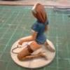
I have been stuck in the house for close to two months now with a partially slipped disc and other lower back problems. Due to one thing and another I really haven't felt like modelling even though I had two Elves sitting on the bench all primed up ready to paint. So after a chat with Mike yesterday he persuaded me to get this one out of the stash and build it straight out of the box. I was going to add some turned machine gun barrels, but will now save those for a later build. The kit is a little awkward, particularly in getting the fighting compartment panels aligned, but I used the interior rhomboid to act as a template and all is good. The number of wheels is fun, but they positively lock into one half of the rhomboid allowing just a tweak here and there to get them all lined up between the two halves. The rhomboid section in the picture isn't glued yet, hence the clamp.
-

Trumpeter German Panzertriebwagen No.16. 1:35
Shar2 posted a topic in Locos, Trains & Layout Reviews
German Panzertriebwagen No.16 Trumpeter 1:35 History Panzertriebwagen No. 16 (PO PzTrWg 16 or PT 16) - German heavy armoured motor car , powered by a diesel engine with an output of 550 HP driven by a Voith hydraulic transmission, was produced by the German company Berliner Maschinenbau-Gesellschaft Actien vormals L. Schwartzkopff in 1942. It is based on type WR 550 D14 armoured locomotive, then fully encased in armour and equipped with two additional crew members for the armoured artillery positions on the two ends of the unit. They were initially armed with two 20mm anti-aircraft gun - 2 cm Flakvierling 38 - but were modified by the crew members. The armament was replaced with Russian 76.2 mm FK 295/1 artillery cannon (as found on type BP42 armoured trains). The thickness of the armour of Panzertriebwagen No. 16 ranged from 31mm to 84mm. This vehicle was the heaviest single-rail armoured vehicle. Only one copy was built, which fought on the Eastern Front. In 1943, PzTrWg 16 was a reserve weapon, which was used to patrol areas threatened by the guerrillas. In the spring and summer of 1944 it was deployed to Army Group Centre. It saw action in the battles of Rawa Ruska and Lublin, then withdrawn to Radomafter, moving the front to the west. From August to September 1944, it ran the stretch of Kielce, patrolling the railway lines between Krakow, Skarzysko and Radom. In April 1945 PzTrWg 16 took part in the battles of Neuruppin. On 1-2 May 1945, it was captured intact in Neustadt (Dosse). The Model The first thing you’ll notice with this kit is the size of the box, it is big. A lot bigger than I had expected, and not only is it big, but when you open it is full to the brim with medium grey styrene. The most notable part is the single piece centre section, which houses the diesel locomotive. It must be one heck of a mould to produce this 340mm x 100mm x 100mm part, complete with openings and some very nicely moulded detail. In fact the moulding of this kit is excellent throughout. With no sign of flash or imperfections other than a few moulding pips and the occasion flow lines. There is nothing that should worry the sort of modeller that would buy this kit. The good news is that this vehicle is still extant so there are quite a few photographs on the interweb that will help with researching for this build. If you include the rail sections, there are eleven quite large sprues, along with fourteen separate parts, one sprue of clear styrene and three sheets of photo-etched brass. There is quite a lot of detail included in the kit, particularly for the engine running gear that unfortunately will not be seen that easily, but YOU will know it's there. The build begins with the construction of the track bed consisting of two long sections, four short sections and the two end pieces, one of which needs to be cut down to fir, which is clearly shown in the instructions. The sleepers are then fitted from beneath the track bed, and again a section at one end needs to be cut down to fit. Turning the bed over you can then slide the tracks through the moulded ties cutting the last two lengths to suit. Each track join is provided with a pair of fishplates included in the kit. Now whilst the track structure can look pretty good out of the box, it may be worthwhile sourcing some scenic ballast, metal tracks, (1 Gauge), and fishplates to improve the realism. To do this it may require the moulded ballast to be sanded/ground off, otherwise it could look like there is too much. All the gear required to do this can be sourced from HERE Construction then moves onto the gun trucks. Each truck is made up of eight wheeled bogies and each bogie is made up from two sides, to which the suspension springs are added. Each of the four axles is fitted with two wheels and capped off with poly caps and the three piece axle ends. Each axle end is then slotted into their appropriate position on each side plate, which is also fitted with eight brake shoes. The end plate is then attached and fitted with an seven piece mounting beam. The lower hull of each turret mount is then fitted out with eight brake actuators and sixteen axle end plates before the axle unit is fitted to the lower hull, ensuring the brake lever fit into the slot in each actuator. Nest, it’s on with the assembly of the buffers and associated coupling fittings. Each buffer is made up of three parts, upper and lower halves and the buffer itself. You need to assemble to buffers with globe ends and four with flat ends and fit one of each to each end of the vehicle trucks once fitted with their mounting plates and three part step which fits to an L shaped beam on the outside of each buffer. For more realism you can buy aftermarket buffers of the correct style, complete with springs, from RB models. The coupling links are then assembled from seven parts which look really good, but again you could possibly replace them with 1 Gauge gear if that is your want. The ends of the turret trucks are complete with the addition of more L shaped angle iron, hose connections, additional clamps, and two six part lamps. To the rear of each truck hull, three more access steps are added. The decahedron style turrets have five fixed plates moulded to the roof and five separate plates which need to be carefully glued into position. The turret is fitted out with the mantlet, pistol port hatch, roof hatch, two additional plates and twelve PE rivets. The rather simple gun barrel is made up of left and right halves with a separate muzzle with an appropriately hollowed out end. Beneath the gun barrel is the prominent recuperator, which is also in left and right halves, and fitted with a PE frame. With the recuperator fitted to the barrel the gun is then glued to the turret base, which is then fitted to the turret. The styrene canvas cover then fits over the gun and glued to the previously fitted PE frame and the turret. With the turrets complete they can be put to one side whilst he modeller gets on with assembling the upper hulls of the turrets trucks. The single piece hulls are fitted out with hand and foot plates, hand rail, rearming and access hatch, which is protected by two protective plates. Although there is no interior the hatch can be posed open and held upright by two clamps on the protective plate ends. The upper and lower truck hulls are then joined together and finished off with the addition of the turret. Once again these assemblies can be put to one side whilst the construction of the engine section is carried out. As with the fore and aft turret trucks the engine construction begins with the assembly of the running gear side plates. Each plate is fitted with the axle mounting plates, suspension fittings, and suspension springs along with the three piece brake accumulator. The plates are joined together via the rear mounted cab plate, and the two cross beams with the axles sandwiched between, unglued. The eight wheels, each with separate balancing weights, are then attached to the axles followed by the two, two piece connecting rod end bearing mounts. The brake mounting frame is then slid between the wheels and fitted with the separate two part brake pads. Each of the connecting rods are made up of four separate rods and connected to each other by bearing joints, after which the rods are fitted to the wheels and end bearing mount. The completed wheel assembly is then fitted to the engine floor which has a separate centrally mounted disc. At this point the large engine casing ends are fitted out with front and rear access doors, hand holds, and viewing ports. On the roof there is another large access hatch fitted both at the front and the rear complete with PE eye bolts, along with two command cupolas, each made up of twelve parts and fitted with six PE parts, mounted fore and aft The large central roof opening is filled with a grill section and fitted with the exhaust cover. The moulded on hatches on the roof of the engine are fitted out with numerous PE brackets and two hand rails. The engine floor with running gear is slide into the body of the engine which is finished off by the fitting of the hinged side plates at the base of the main body. The two turret trucks are then put on the rails and joined together by the engine, thus completing the build. There is only one paint scheme shown on the colour printed sheet, and that is of the train in overall Panzer Grey. Conclusion Whilst this kit is not really that difficult to build even though there are quite a few parts, the result will be a really impressive and unusual model to have in your collection. As mentioned above there are plenty of opportunities to add further detail it should look great out of the box with the addition of weathering to both the tracks and the train. As with all of Trumpeters rail kits the tracks can be joined together form each kit to make a long and more complex train or diorama. Very highly recommended. Review sample courtesy of UK Distributors for -
Stug III Ausf G Early/Late ET Models 1:35 These five sets are for the Dragon Smart Kits with two sets for each of the Early and Late versions along with the fender set which is universal. There doesn’t seem to be any crossover between the sets so the modeller can add as much or as little extra detail to the kit as they see fit. As usual each set is contained in a thick poly bag with a card header and the instructions on the standard green A4 sheets. They are pretty clear and concise, but careful reading will reap rewards when it comes to fitting the sub assemblies to their respective positions. Some kit detail will need to be removed before adding the etched parts, plus brass and styrene rod will be required from the modellers own stock. Basic Set Early Version. (Early, EA35-225), (Late, E35-226) Although titled a basic set, these far from it, with lots of beautifully relief etched brass and a length of brass wire. Each set contains three sheets of relief etched brass, each of differing sizes. The vast majority of parts are the same for each set with only one or two differences. As usual a lot of the parts contained on the sheets are used to replace the many clamps and brackets for the pioneer tools, fire extinguisher, track fittings, and storage box straps. The gunners cupola is completely replaced with new brass parts and includes the raised plate, hatch, and hatch fixtures and fittings. The early set differs with the inclusion of the machine gun shield for the commanders hatch which is also provided with new hinges and locking mechanism. The smoke dischargers are provided with new brackets whilst the headlights are improved with new brackets and support mounts. The various intakes are fitted with new mesh parts, along with new plates for the exhaust. On the rear deck there is a new storage box and a new framework and its supports. Basic Early Basic Late Schurzen (Early E35-227), (Late E35-228) Due to the differences between the two styles of Schurzen the Early set contains two sheets of brass whilst the late set only includes one sheet. The two part set provides all the parts to make up the two large side screens that fit along the side, covering the return rollers and the corresponding track along with the four parts that make up the shield along the upper section of the fighting compartment. Naturally all the requisite hangers and brackets are also provided. The same goes for the Late set, only the four upper panels are not included, just eh large side panels. Shurzen Early Shurzen Late Fenders (E35-107) This two sheet set can be used for either versions of the Dragon kit and contains two complete fender braces, the fender decks and their associated fixings and fixtures including mudguards front and rear. The detail on the fender decks is really well done with the anti-slip tread looking great. Conclusion ET really know how to make superb detail sets for the modern modeller. These are well up to their usual standards, and whilst not meant for absolute novice modellers they aren’t so difficult as to preclude those with even only a modicum of experience. It’s just a matter of choosing your Stug III version and adding the brass. Highly recommended. Review Sample courtesy of
-
Skoda 42cm Heavy Siege Howitzer Takom 1:35 History The 42 cm L/15 Küstenhaubitze M. 14 (42 cm, 15 calibre, Coastal Howitzer Model 14) was a super heavy siege howitzer used by Austria-Hungary during World War I and by Nazi Germany during World War II. It was designed to penetrate the weakly armoured decks of modern dreadnoughts in accord with the prevailing coastal defence doctrine that held it was better to attack the weakest point with high-angle indirect fire than to attempt to challenge their strongly armoured sides with exceedingly expensive guns that had to be equally as well armoured to withstand return fire from the battleship. Howitzers were significantly cheaper and could be hidden behind hills to avoid the expense of armouring them. The known problem of hitting a moving target with indirect fire was to be alleviated by massed fire from multiple weapons all firing with the same data. At any rate, two howitzers were bought to defend the main Austro-Hungarian naval base at Pola on the Adriatic. They were to be installed on a turntable carriage with an armoured dome able to traverse a full 360° for all-around defence. The turntable rested on a ball-race ring, set in a concrete foundation. However, with Pola unthreatened after the outbreak of the war, it was decided that they might be better used in support of the Army. The first howitzer was already fixed in place, but the second wasn't yet installed and Skoda was able to adapt it for mobile use by January 1915. On the 14th of that month, Howitzer No. 2, assigned to Küstenhaubitze Batterie (Coastal Howitzer Battery) no. 1 fired its first shot at the railway station in Tarnow, Austrian Poland. Eight M. 14s were eventually ordered (along with a spare barrel and cradle), although one was retained by Skoda. Barrel production was very slow, so slow that barrels originally ordered for coastal mounts were put into service as part of the 42 cm Autohaubitze (Motorized Howitzer) M. 16. One surviving gun was used in 1940 by Nazi Germany to shell the Ouvrage Schoenenbourg from a position near Oberotterbach; the 60- and 80-cm guns later used by the Third Reich (for example at Sevastopol) were not ready in time for the French campaign, so World War I vintage heavy pieces like this Skoda and also a surviving Gamma-Gerät tube had to be used. The Skoda, apparently the sole M17 model, entered German possession following the annexation of Czechoslovakia in 1938/39, and was renamed from 42 cm houfnice vz. 17 to 42 cm Haubitze(t); it also served at Leningrad and Sevastopol, even though its barrel life was rated to only 1,000 rounds. The Model As with the SKODA 30.5cm reviewed HERE this kit depicts a M.1917 as it was used in the siege of Sevastopol in 1942, and according to history it was the only one. Contained in the top opening box, with a stylised photograph of the weapon with Eric Von Manstein standing to one end, whilst another weapon is seen firing on Sevastopol in the background, are three sprues of dark grey styrene. All the parts are free of flash, but there are quite a few flow marks and a few ejector pin marks on visible faces of the larger parts, but look to be fairly easy to clean up as there isn’t too much detail around them that could be lost. As per the previous kit Takom have used slide mould technology very effectively in the production of the barrel parts allowing for a pretty seamless build, although there is less in this kit so there will be some cleaning up of the barrel required. The small landscape A5 booklet of instructions is very clearly printed and easy to use. Construction begins with the assembly of the of the centre section of the gun which includes the trunnions, the breech, and breech block, which are all made up of two parts. Two collars are fitted to the front of the centre section, followed by the outer barrel. The assembled breech and breech block are then attached to the rear of the trunnion section, after which the three piece inner barrel is slid in from the front. The single piece end section of the inner barrel has a nice representation of the rifling, although if you look really closely they are straight and not curved which is a limitation of the moulding process. On the underside of the gun a rounded base plate is affixed along with a shaft fitted on the centreline, between the recuperator ends. At this point the central circular base section is assembled form the two halves provide and fitted with four tabs, which will slot into the outer base when complete. The traversing gearbox is fitted with etched lengths of bolts before being attached to the left hand trunnion mount and finished off with the attachment of the traversing wheel, which is assembled from three parts, the wheel, shaft and handle. The elevation wheel is fitted with its handle, whilst the two footplates are attached to the left hand mount, which is then fitted to the base. The elevating shaft is fitted with two cogs and attached to the inner face of the left mount. Do not glue this shaft if you wish to have the gun barrel movable. The shaft is covered by a large plate fitted to the front of the mount, after which the right mount is fitted to the base, ensuring the elevation shaft is fitted correctly, followed by a curved plate fitted to the upper rear of the mounts. The traversing lock/brake handle and clutch unit is fitted to the four piece housing and the whole assembly is attached to the base, just next to the left mount. To the rear of the mounting there is another gearbox, with a double winding handle attached. This is then fitted with a double wheeled contraption which hauls the shells up to the breech. This is quite a complex assembly so a bit of care will be required. The build is completed by the assembly of the outer base halves to which the circular base is then slotted into position. The kit also includes one figure, that of Eric Von Manstein who commanded the 11th Army in the Crimea during the bloody siege of Sevastopol in which this howitzer was used. Strangely the paint chart shows two different schemes, one of green over grey when used by the 787th artillery division at Sevastopol and the other in grey overall, also at Sevastopol. Since there was only on gun of this type available it does seem a bit odd to have two schemes, but there you go. Conclusion As with the 30.5cm siege howitzer this is one pretty obscure weapon. Whilst there are not too many parts, they are all very well moulded and when complete this will look most impressive on the shelf, or as part of a diorama. Unfortunately, as with the earlier kit, no crew are provided, and in this case no ammunition either, so some scratchbuilding will be required if you go down that route. Highly recommended. Review sample courtesy of UK Distributors for
-
Russian Machine Gun Barrels 1:35 Master Continuing our journey through the bundle of review items that Master Models very kindly sent us, we have here three sets of Russian 14.5mm heavy machine gun barrels. Each packet holds just one barrel, along with the cooling jacket, etched sights and resin handles. Whilst this is ok for the type used on the BTR-60/70/80s and BRDMs the other two are for use with ZPU 1/2/3/4 systems, for which you will need to buy up to three more barrels to complete the model. [GM-35-009] – This barrel comes with the elongated cooling slots on the jacket and is to be used on the ZPU systems. [GM-35-010] – Also to be used on the ZPU systems is this version of the barrel which has round cooling holes on the external jacket. [GM-35-011] – This barrel can be used on all the vehicles mentioned above, although it was widely used on many other vehicles so you will need to carry out some research before buying. Conclusion There’s not much more I can say about these sets other than be a little wary of the BTR version cooling sleeve with the elongated holes as it has a tendency to bend quite easily. Very highly recommended. Review sample courtesy of Piotr at
-
German Dingo 2 GE A3.3 Patsi Revell 1:35 Since its introduction in 2000 the Dingo Armoured Personnel Carrier (APC) has developed into a true all-rounder within the Bundeswehr. Both Dingo 1 and 2 provide an ideal combination of protection, cross-country mobility and speed. The ATF Dingo 2 GE A3.3 Patsi version has been used in Afghanistan since 2012 as a reconnaissance and security vehicle. The 6 occupants enjoy a maximum of protection thanks to excellent land-mine protection afforded by the V-shaped deflector under the safe cell. For self-protection, the Dingo is normally equipped with a type FLW 200 weapon platform which can be optionally fitted with a .50 calibre (12.7 mm) machine gun or an automatic 40 mm grenade launcher. Technical improvements over its predecessors include amongst other items optimization of crew protection, a hard-top over the cargo platform and IR driving lights to improve night vision capability. The Model Originally released in 2013 in the vehicles A2 form, this kit has new parts added to upgrade it to the A3.3 variant. Contained in one of their controversial end opening boxes are eight sprues of green styrene, plus two clear sprues, four vinyl tyres and a length of wire. The parts are very clean and nicely moulded with no sign of flash, but with quite a few moulding pips and rather awkward moulding points, particularly between the window openings. A lot of the larger parts have prominent flow lines, which whilst a little annoying shouldn’t cause too many problems under a coat of primer. There are also quite a few very slight sink marks on parts like the chassis rails but are worse on the rear view mirrors and more annoyingly on both sides of the vehicle sides between the doors. There are a lot of imperfections from where the ejector pins have been rather enthusiastic. Although they haven’t punched through these marks are slightly visible on the outside of parts. Like the flow lines, these should disappear under a coat of primer and paint, just be aware of them. The build begins with the construction of the chassis. This consists of two longitudinal rails, to which the front mud guards, rear air accumulators, front shock absorbers are fitted before the two rails are joined together by six cross members, the transfer gearbox assembly and power take off box. There is a rudimentary engine included in the kit consisting of jut two parts, but since you won’t see much, if any of it, it’s really just so that the drive shafts have somewhere to fit. Witht eh chassis assembled it is then fitted out with accessory boxes, exhaust silencer, front bumper beam, rear bumper, complete with towing eyes, lights, tow hook, and cover plate. Moving onto the drive train, the four wheels are assembled, each from a vinyl tyre plus inner and outer hubs before being put to one side. The axles are each made up of a single axle part, to which the brake discs are fitted. The front axle also has the steering rack and ball joints attached. Both axles are then each fitted with a two part drive shaft casing and their respective support arms. Before the axles can be fitted to the chassis, the suspension springs, airlines and front skid plate need to be added. Followed by the anti roll links, engine assembly and exhaust pipe. The kit comes with a nicely presented and pretty full interior which begins with the fitting of the front foot wells into the single piece floor pan, along with cross compartment mounting rails. The centre console is assembled form two side pieces and two sections, which look like comms/control units. The instrument binnacle is fitted with the decals instruments, foot pedals, steering column, steering wheels and passenger side console. Other sub-assemblies include the six two part seats, the three part radio set, storage shelve unit, two part IR/TV console and controller for the roof mounted machine gun. Once assembled these are then glued into their respective positions. It should be noted that the headrest of the rear centre seat needs to be removed as there is already one on the rear bulkhead. Moving the outside of the vehicle the front valance is fitted with the clear windscreen, windscreen surround and the three wipers. Inside the sun visors and compass are attached to the top of the frame whilst a map display unit, complete with decal is fitted to the bottom of the frame on the right hand side. Each of the four doors are moulded as a single piece, onto which the door cards and thick clear parts, (obviously attempting to represent armoured glass), are fitted, along with the door handles. The completed doors are then fitted to the body and can be posed open if required. The two sill plates are then fitted with two footsteps and glued into position under the door frames. Also fitted to the underside of the floor pan are two storage boxes, and the wheel arches for the four wheels. Meanwhile, the underside of the roof is fitted with an air conditioning, overhead control box and gun mounting display. The front valance, hull sides, rear bulkhead and roof are all joined together to make the complete armoured box that is the crew compartment. The roof is then fitted with a crew hatch, GPS antenna and aerial mounting plate. Unusually for a four wheeled vehicle this one has a separate compartment fitted behind the main crew compartment. This is made up of a lower section which is fitted with the rear mudflaps, lights and storage racks. To this the sides, rear, and roof are attached, followed by the two rear access doors complete with their handles. The crew and storage compartments are then attached to the chassis followed by the bonnet, bonnet sides and grille. The main machine gun mount is quite a complex affair in that it is constructed from five parts, onto which a further six parts that include the sight, and spent cartridge bag are attached. The modeller then has a choice of which weapon to fit to the mount. You have a choice of either a Browning 50 cal with its associated ammunition box or a 40mm automatic grenade launcher and its associated ammunition guide. The completed unit os then fitted to the top of the crew compartment roof via a mounting ring. The model is completed with the fitting of the two pairs for rear view mirrors, tow bar, and a pair of aerial mounts to the roof of the storage compartment. The aerials can be made up using the metal wire provided. Decals Along with the instrument and screen decals mentioned above, the decal sheet includes several placards for inside the cabin, German crosses and unit shields for the hull, plus two pairs of completed number plates. As an added option for those modellers who wish to build a particular vehicle a pair of blank number plates are also included along with a whole selection of separate numbers to finish them off. The decals are well printed in Italy, so presumably by Cartograf. They are in register with good colour density and no bleeding between colours. Three vehicle options are provided in the kit and these are for:- Dingo A3.3 of the Bundeswehr ISAF, Afghanistan 2012 Dingo A3.3 of the Bundeswehr ISAF, Afghanistan 2013 Dingo A3.3 of the Bundeswehr, 2015 Conclusion Whilst I’m not overly enamoured with the green styrene used in this kit there is a lot of detail provided that will make up into a good looking model. Shame about some of the imperfections and sink marks on some of the parts, but these shouldn’t cause too many problems to the seasoned modeller. There seem to be a number of vehicles from different countries that appear to be following a similar format, but they’re still an interesting vehicle to have in any collection. Recommended. Revell model kits are available from all good toy and model retailers. For further information visit
-
Diorama Sets, Camouflage Netting ET Models 1:35 Continuing with the additions to their diorama line of products, ET Model have now released two new styles of camouflage netting. Each sheet comes in their standard poly sleeve with a cardboard header. Both sheets are made up of very thin brass sheet which will aid in the making them look cloth like material once slightly scrunched up. Type 1 has large rounded perforations whilst the Type 2 has much smaller rounded perforations. Each can be used in conjunction with the separate leaves found in the previously released sets reviewed HERE Conclusion Having never used these types of netting before I can’t really say how well they work, but their thinness should be an advantage in getting them to look pretty realistic. They could certainly be a useful alternative to using medical bandages. Highly recommended. Review Sample courtesy of
-
BMPT Terminator 1:35 Eduard The release of the Meng Terminator was a great surprise and was received with much delight amongst modern armour modellers. Now Eduard have released this set to add the extra sparkle that some modellers like to add to their creations. Contained in Eduards now infamous sleeve packs, the two medium sized sheets of relief etched brass Sheet one contains a myriad of smaller items, some of which require the kit parts to be modified or removed before the etched parts can be added. These include the handles along the side plating, storage boxes, and rear decking, plus a host of new brackets and angle plates in various positions throughout the main surfaces of the tank. New grilles are provided for the engine intakes and air conditioning unit and new straps for the fuel tanks. The is a section of plating with dimple marks on the front face and these need to be improved with the use of a ball point pen on the rear face. The second sheet comprises mostly of strakes and fittings for the anti RPG bar armour fitted to the rear and sides of the vehicle. Each section is made up of the outer frame and the individual bars. Patience and great care is the order of the day for making these up to ensure everything is aligned. There are six short sections which need to be joined together vertically by the use of modeller provided styrene/brass rod. The long section is a standalone item. The lights, missile tubes and smoke launchers are also given several new or replacement items to improve their look. Conclusion As good as the Meng Terminator kit is, and this pretty much goes for any modern kit, Eduard always seems to find a way of enhancing them. This set is no different, although at least the bar armour is a better scale thickness than can be achieved with injection moulding Highly recommended Review sample courtesy of
-
- 1
-
-
- BMPT
- Terminator
- (and 2 more)
-
StuG III Ausf.G 1943 for Dragon 1:35 Eduard The Dragon StuG III Ausf.G has been out for quite a few years now, but is still a very nice kit. Yet Eduard have only now released this single sheet set 36-281. This may go to show that the kit didnt have too many flaws or the fact that Eduard have covered every new kit that has been released and its now time to look at Dragons re-boxings. Contained on one medium sized sheet are a plethora of small parts, the majority of which appear to be replacement clamps and fittings for the pioneer tools. The fire extinguisher receives a new holder, complete with straps and clasps, as does the jack and the shovel also gets a new blade. In addition to the replacement parts the set has new items that Dragon appears to have missed. These include new brackets for the frontal armour, rear storage bin, new surround for the wooden crate, complete with brackets, and straps, whilst the hatch on the rear decking is fitted with hasp/clasp and even a padlock. On the rear bulkhead of the crew compartment there is a new channel section plus brackets, and is attached with two wingnut bolts. Lastly, there are several grab handles for the machine gun shield and crew hatch. Conclusion Although this is a relatively small set, there is enough included to add that extra zing to what is already a very nice kit. Quite fiddly, but well worth it. Highly recommended Review sample courtesy of
-
ET Models Citroen 11CV Staff Car Detail Set – E35-229 for Tamiya
Shar2 posted a topic in Aftermarket
Citroen 11CV Staff Car Detail Set E35-229 ET Models 1:35 The Tamiya kit of the Citroen 11CV Staff Car has been out for nearly six years, and its only now that ET Models have released a small, but useful detail set for it. The nicely produced single sheet of relief etched brass contains the prominent grille with the Citroen logo and surround joined at one edge, so that when folded give a nice 3D representation of the real thing. Also included are a pair of mudflaps that are situated behind the front wheels, the front number plate, rear number plate, for which you will have to carefully remove the light off the kits part and glue to the etched part. The kits rear view mirror and windscreen wipers are also replaced with etch. Conclusion Whilst small, this set adds enough parts to give a lift to the standard kit, particularly the grille and logo. Simple to use, with no major folds required, so would be of use to all but the most novice of modellers. Highly recommended. Review Sample courtesy of -
Diorama Sets, Leaves and Sunflowers ET Models 1:35 ET Models have now released another pair of sets of what can only be described as diorama material. Each set has two sheets of etched brass, leaves type A are identical, whilst the sunflower set has different sheets providing various sizes of flower to be affixed to the top of each plant. The leaves set can be used for foliage in a diorama of as camouflage on military vehicles, whereas the sunflowers are more limited in their use, but will look good painted up in a farm or garden setting. Conclusion I’ve not had a chance to use sets like these before and whilst initially I wasn’t convinced of their usefulness, I can now see how they can be incorporated into a diorama. Some careful detail painting will be required, but the possibilities are really only restricted by the modellers imagination. Recommended. Review Sample courtesy of
-
SpPz 2 Luchs heavy armoured car Takom 1:35 History The Spähpanzer Luchs is a German 8x8 amphibious reconnaissance armoured fighting vehicle in service since 1975 with the German Army, who used 408 units in their armoured reconnaissance battalions. It was developed by Daimler-Benz between 1968 and 1975, replacing the M41 and the Schützenpanzer SPz 11-2 Kurz. The all-wheel drive Luchs made by Thyssen-Henschel (now: Rheinmetall) is well armoured, has an NBC protection system and is characterized by its low-noise running. The eight large low-pressure tyres have run-flat properties. At speeds up to about 50 km/h, all four axles can be steered. As a special feature, the vehicle is equipped with a rear-facing driver with his own driving position. Up to the first combat effectiveness upgrade in 1986, the Luchs was fully amphibious and could surmount water obstacles quickly and independently using propellers at the rear and the fold back trim vane at the front. The 20 mm Rheinmetall MK 20 Rh 202 gun in the turret is similar to the one in the Marder IFV. The upgrade to the Luchs A1 starting in 1986 included the incorporation of a thermal observation and gunnery system, which replaced the original infrared/white light night vision system mounted to the left of the turret. VHF radios have been the German SEM 25 / SEM 35 FM short range radios from LORENZ. HF long-range radio was the AN/GRC 9 with the LV 80 100 Watts RF amplifier for Morse code. This was replaced by the XK 405 100 Watts SSB HF radio made by Rohde&Schwarz in Germany and the incorporation of the new SEM 80/90 radio system gave it the designation SpPz 2 Luchs A2. The Luchs was replaced by the Fennek in Bundeswehr service. The Model The kit is packaged in a very attractive top opening box with an artists impression of the vehicle in action on the boxtop. Inside there are seven sprues of sandy yellow coloured styrene, the two hull halves and turret. Also included are a set of springs for the suspension, a sheet of etched details, a DS style flap, decal sheet and a pair of poly caps. Unusually, Takom have provided two complete sets of tyres, depending on whether the model is going to be built as the A1 or A2 version. The parts are very nicely moulded, with no sign of flash or imperfections, but there are loads of moulding pips which will add to the time of cleaning up the parts before use. As with most kits of these types of vehicles most of the work is concentrated on the drive train and suspension. This kit is no exception, beginning with the fitting of the bump stops, light cluster assemblies, the eight, 2 part, shock absorber assemblies and mud flaps to the lower hull section. The four suspension arms are then fitted with their pivots and once fitted to the lower hull are fitted with the eight individual metal springs. Each of the four axles are made up of upper and lower halves, to which the lay shaft ends, spring mounts and transmission covers are attached, followed by the ball joints, steering racks, support arms and torque links. Each of the axles is slightly different, so read the instructions carefully and note which axle fits where. Between the second and third axle is a transfer box fitted, this, and these axles are connected via a drive shaft, with the first axle connected in a similar fashion to the second and the fourth to the third, followed in a similar manner by the steering connecting rods. Each of the hubs are made up of the inner hub, brake drum and an outer connecting disc, but do not attach the wheels just yet. Two headlights are then assembled from their five components, including a PE bracket which needs to be carefully bent to shape, before fitting to the hull along with their respective protective bars. Before fitting the upper hull, (a task which I would have done first rather than at this point), a several 0.8mm holes need to be drilled out depending on which mark of vehicle is being built. With the upper hull attached the rear panel assembly is fitted. This is made up of the panel, engine grille, rear light assembly and towing eye. Seeing that this vehicle is amphibious it’s no surprise that it has a separate propulsion system, in the form of two propellers fitted. These are each made up of the two part mounting, propeller, and front boss. These are they attached to the underside rear of the hull. Turning the hull right side up the splash plate is fitted to the front glacis plate, either stowed or deployed. Depending on which version is being built ensure the correct tyres are being fitted at this point. Each tyre is slid onto the inner hub and sandwiched into place by the outer hub. With the model sitting on its wheels the many and various hand holds, aerial mounts, pioneer tools, towing cable and drivers vision ports are fitted, along with the two drivers hatches. Details differ between the two versions, which is why different holes need opening up earlier in the build, so there’s no changing your mind half way through the build. Next to be fitted are the two rear view mirrors, port side exit hatch, fuel caps, and unidentifiable tubes on the rear decking. There is a five piece cover that surrounds these tubes tubes which is a mixture of styrene and PE and fitted aft of the turret ring. Finally it’s onto the business end of the vehicle and the assembly of the turret. The turret ring section is fitted from the inside with the gun mount and trunnion, the assembly is then attached to the single piece upper turret section. The gunners hatch, rubberized trunnion cover, an unidentifiable box on the turrets right front, followed by the main gun. The eight smoke dischargers are attached four per side, whilst on top the commanders hatch, and training light are fitted. The A1 version has only one multipart sight fitted to the top of the turret, complete with optionally posed cover doors, whilst the A2 version has two of completely different design, one each in front of both upper hatches, the right hand one covered by a prominent cage structure. The MG42 machine gun is then fitted with the trigger handles and attached to its mounting plate, which in turn is fitted to the scarff ring. This assembly can be fitted to the left turret hatch or in its dismounted position on the rear decking. Once complete the turret is fitted to the hull, finishing off the build. Decals The decal sheet, which is actually quite colourful considering the markings are to be used on an armoured vehicle. They are very nicely printed in register, good opacity and with little carrier film. The writing is pin sharp and can easily be read with the naked eye. The painting instructions come on two double sided A5 sheets and have obviously been produced for use with Ammo by mig paints, using their colours on the call outs. There are two vehicles in overall NATO green and two in three colour camouflage of NATO green, NATO brown and matt black. Conclusion Whilst this is a magnificent and surprisingly large model it’s not that complicated, although the suspension and drive train will require some care to get positioned correctly. Dry fitting the hull sections together reveal that there may be a problem getting it aligned and gap free as the pins aren’t the most prominent seen in a kit. As mentioned above it may be best to fit the two parts together at the beginning to get it all fitting correctly, rather than trying to do it with all the suspension attached. Other than that, there isn’t much that should worry any modeller of intermediate skills and above. Highly recommended. Review sample courtesy of
-
This one has taken a while to build, not due to it's complexity, but the fact that I'm still suffering from chronic back pain. I also managed to knock up a rudimentary generic base for it. I used Mig and AK interactive weathering powders and washes with AK Interactive resin coloured with artists acrylics for the mud on the tracks etc.
- 16 replies
-
- 15
-
-
These have been tempting me from my stash for too long, and here I'll try to demonstrate the techniques I use to build MiniArt's 1/35 German Street (36037) and hopefully incorporate their Metal Fence (35549). MiniArt kits are manufactured in the Ukraine and offer a useful base for diorama modellers and those wishing to venture into the art of building dioramas. The smaller parts and fittings are injection moulded, whereas the bulk building parts are vac-formed in quite thick plastic. This may seem daunting to those used to working with injection moulded parts, but really should not cause trepidation. To remove the backing plastic from the moulded sheet use a bradawl, Olfa P-Cutter or a knife to score around the edge of the moulding. Do not try to cut right through the plastic, therein lies catastrophe; simply run around the edges. The blade may separate the plastic, or the waste can be removed by bending the sheet away from the moulding, causing the score to break. As always, this should be done with care and not in a reckless fashion. I find it best to use all these tools and methods. Some work better than others depending upon the situation, so it’s well worth experimenting to find the methods that work for you. A nail file or sanding stick can be used to tidy up the edges. The walls are usually made from two pieces. To aid their marriage, use the offcuts to make tabs. Stick these on the inside edge of one piece, overlapping to receive the second piece. If you have tube glue from a Gift Set and wondered what to do with it, this is the task to use it on. Run glue around the edge and on the tabs. Offer the walls to each other and use masking tape to hold them together while the glue sets. I find it best (in most cases) to use side cutters to remove injection moulded parts from the runners. Excess plastic from the sprue gates can be cleaned up with a knife or sanded before being offered for assembly. Be sure to remove any ejector pin marks, either by filling or sanding down (or both). I decided quite early on that I would not strictly follow the instruction sequence as published. For example, I thought it would add interest to have some windows open, but would decide which ones when it came to fitting them.
-
Zil 131 Heavy Utility Truck Revell 1:35 History The ZiL-131 is a general purpose military truck. It's production commenced in 1966. It replaced the previous ZiL-157. Production ceased in 1994 with nearly 1 000 000 of these military trucks produced. Despite it's age the ZiL-131 is widely used by Russian military, as well as a number of other countries. Vehicle has a conventional layout. The baseline model of the ZiL-131 is a cargo truck. It has a payload capacity of 3 500 kg off-road and 5 000 kg on hard surface roads. It is used to carry troops, cargo and other military equipment. Cargo area is covered with bows and canvas cover. Vehicle can also tow trailers or artillery pieces with a maximum weight of 4 000 kg off-road and 6 500 kg on hard surface roads. An all-metal cab of this truck provides seating for the driver and two passengers. The ZiL-131 is powered by a V8 petrol engine, developing 150 hp. Engine is coupled with a 5-speed manual gearbox. Vehicle has a full-time all-wheel drive; however the front axle can be disconnected on hard surface roads. It is also fitted with a central tyre inflation system. A self-recovery winch was fitted on some models. The Model This is a re-pop of the ICM kit released in 2014 and comes in the rather weak open ended box we’ve come to expect from Revell, but with a nice artists impression of the truck in use. Inside, there are six sprues of dark caramel coloured sprues, a sprue of clear, eight vinyl tyres and a small sheet of decals. The parts are well moulded, with no sign of flash and fewer moulding pips than normally found in these types of kit. While the parts look good, the moulded details appear a little soft and indistinct in places. As with most trucks the build begins with the chassis, but before the work can begin on those there are a number of sub-assemblies required. These include the front, middle and rear cross members, transfer box frame, transfer box and air accumulator tanks. The chassis rails have the front leaf springs and rear suspension mounts pre-moulded into them. With the main chassis structure assembled and the sub-assemblies fitted, the rear corner bumper parts and towing hook are attached along. The fuel tanks are then assembled, each made up of three parts including the fill cap and these are then fitted to their support trays which are in turn attached to the out chassis rails, as are the rear engine mounts. The engine itself is a good balance of detail and ease of build. The gearbox and block are provided in two halves, with the drive shaft moulded onto one half. The single piece cylinder head is fitted, along with the fuel filter, oil filter, oil cooler, alternator and inlet manifolds. The three accessory drive belts are fitted to the front and finished off with the fan. The completed engine is then fitted into the chassis before the large two piece air filter unit is attached. The exhaust system comes as one long part to which the other half of the silence is attached before the system is attached to the chassis. There is an option to fit a large winch to the front of the chassis and this is made up of eight parts, just make sure the winch drive shaft is connected to the transfer box before gluing the unit in place. With the winch in place the radiator is attached, followed by the front bumper which consists of five parts. The rear suspension consists of the two rear axles/differentials which are then joined together with the two leaf springs. Each of the six wheels are single piece units to which an air regulator is fitted, followed by the vinyl tyre. The rear wheels are fitted to the rear suspension after which the two gear housings with drive shafts are attached to the top of the differential. The whole assembly is then attached to the suspension mounts on the chassis followed by the fitting of the suspension arms and a lower cross member. The front differential is assembled from two halves and fitted with the gear housing, drive shaft and steering rack, before being fitted to the front leaf springs along with the wheels, shock absorbers and suspension arms. The spare wheel is fitted with a swing arm style fitting then into the two piece wheel cage which also contains the outer panels of the generator box which is finished off with the fitting of the other panels and the whole assembly fitted to the top of the chassis. Moving onto the cab which is made up of windscreen/front valance, two bonnet sides plus floor pan, and fitted out with the steering column, steering wheel, individual foot pedals, gear sticks, and the seats, which are each made up of the squab, backrest and two armrests/support frames. The rear bulkhead is then fitted with the rear window and attached to the rear of the cab. This is then followed by the windscreen, wiper and roof. The cab doors are separate and poseable whether the modeller wants them opened or closed. They are made up of the door, “glass” and door card, to which the window winder, door handle and grab handle are attached. The doors are then fitted to the cab. The two front wheel arches are fitted with the large headlight cluster into which the clear parts are added, and then attached to the front chassis before the cab sub-assembly is positioned over them. The bonnet and front grille are then fitted, completing the front end of the model. The final few sections in the instructions deal with the assembly of the truck bed. The bed itself is fitted on the underside with the lateral and longitudinal support beams then, on the upperside with the front, side and rear panels, and has the option of having the interior bench seats posed either folded or extended. The underside rear is fitted out with the rear mudflaps, reflectors and the division board. With the bed assembly attached to the chassis it’s only a matter of attaching the wing mirrors, spotlight, exterior door handles and the tilt rails, which unfortunately come moulded together so there isn’t any way of making a tilt other than scratchbuilding one, thereby finishing the build. Decals The small decal sheet contains markings for four vehicles these are:- NVA, (East German Army) 1980 GSTD/GSSD (Soviet Army), East Germany, 1980 Russian Army, 2000 Soviet Army, Afghanistan, 1980 The sheet includes instrument decals, division markings, unit markings and vehicle identification numbers. Conclusion This appears to be a much simpler build than some of the recent truck releases with seen. That said it still looks like a great kit of this rugged looking truck. Whilst not having that much in the way of different paint schemes, it would make a great practice piece for heavy weathering. It’ll also make for a different quick build between making heavy armour. Highly recommended. Revell model kits are available from all good toy and model retailers. For further information visit or
-
British Mark IV Tadpole Takom 1:35 History[/size] Tadpole tails were an innovation designed to improve the trench crossing ability of Rhomboid tanks. They were not a success and were apparently only ever fitted to several trial vehicles. Three vehicles were fitted with tadpole Tails by Central Workshops in France. In March of 1918 a male and Female Mk.IV were fitted with Tadpole tails. The work was started on 6th March 1918, the first tail being fitted by the 18th; the second, strengthened tail was fitted by the 23rd. At least one other Mark IV male was fitted with Tadpole tails and used in trials at Dollis Hill, these trials included fitting a stokes mortar between the lengthened tails. On 5 August 1918 Mk V male, 9001 was fitted with a tail and issued to No.3 Advanced Workshops. A Mark V female, 9277 was fitted with a tadpole tail, possibly at Fosters yard where this tank had given a (Tadpole tailless) demonstration to King George V. Three hundred sets of tails were manufactured and shipped to France, the first arriving in May 1918, they were never fitted. The Model The kit is packaged in a very attractive and sturdy top opening box with an artists impression of the vehicle on the front. Inside there are eight sprues of caramel coloured styrene, which is becoming the norm for Takom, on small fret of etched brass, and a bag of individual track links. The moulding of the parts is superb with no signs of flash although there are quite a few moulding pips. The parts are suitably covered in well rendered bolt heads and rivets but here are some awkward sprue gates which will need to be carefully removed and fettled. The hull and sponsons are each made up of individual panels so care will also need to be taken with alignment, but having built the Takom Mark IV Male, I found that they actually went together really well with no requirement for filler. The build begins with the assembly of the small commanders/drivers cupola complete with poseable hatches, although there is nothing of the interior to see and centrally mounted Lewis machine gun in its ball mount. The hull is made up of the individual plates which, due to the possible alignment problems, to alleviate this it may be best fitted to one of the inside rhomboid sections. The is a large towing shackle and plates fitted to the front panel, followed by the exhaust plates and one part of the unditching beam strake plates, top hatch surround and strengthening ribs are fitted to the top deck. The exhaust consists of the two parts silencer and single piece tube. The tube is completely plain, whereas, for the most part the area next to the top hatch was covered in asbestos, best shown using tape wrapped around the area. The stowage box complete with exhaust cover is assembled and fitted to the rear of the upper decking, whilst the upper hatch is glued into position along with six tie down eyes to the upper storage box and the exhaust silencer is fitted with PE straps. As with the Mark IV the Tadpole was fitted with an armoured fuel tank box on the rear of the hull between the rhomboids, this is represented by five plates glued together and attached to the rear hull panel, with the rear mounted radiator and its cover. Being mirror images, the rhomboid sections of the tank go together in the same way with each of the inner and outer panels being separated by individual plates and the inner faces of the sponson openings. The rear mounted drive sprockets are fitted and, in this, kit the drive chain assemblies, as found in the earlier Mark IV kits, is not used, making construction a whole lot easier. The front mounted idler wheel is mounted before the 33 road wheels are assembled and clicked into position before the rhomboid plates are joined together. Unlike the Mark IV tanks where the tracks were a little on the frustrating side, this kit comes with the super click together indie links. These take only a matter of seconds to put together and the whole run can take as little as 10 minutes to create. The tracks can be left off till end of the painting as they can be clicked into place once everything is finished. If required the kit does include a set of grouser that can be fitted to the tracks although the instructions don't call on them to be used. The main guns come with complete breech detail which unfortunately will never be seen and are fitted with the splinter shields and barrel before being fitted to the mounting via a poly cap. The sponson plates are then built around this and the Lewis gun with ball mount also attached. The completed sponsons are then glued into position on the sides of the rhomboids. The Tadpole differed from the earlier style tanks in that they could also be armed with a mortar mounted on a large plate on top of crossbeams between the rhomboids. The mortar is made up of two halves bi-pod and elevation wheel before being affixed to the mounting plate before the rhomboid assemblies are fitted to the hull, thus completing the build. There are no decals provided with this kit, but I’m sure the modeller can make up his own identification numbers quite easily. Conclusion Ok, so this vehicle never made it to the front line, but at a least a few were modified and tested and the extensions were sent to France for use, it does make for a very interesting model. The fact that the drive chain assemblies and original indie link tracks aren’t used with this kit actually makes it a lot easier to build it will be a nice fun mojo reliever and you can got to town on the weathering. Very highly recommended. Review sample courtesy of UK Distributors for