Search the Community
Showing results for tags '1:32'.
-
 Seatbelt sets 1:32/1:24 HGW Continuing their selection of highly detailed seatbelt sets, HGW have released two new sets, one in 1:32 and one in 1:24. If you want super detailed seatbelts for your models then these will certainly fit the bill. The 1:32 set, for the Zoukei Mura Douglas A-1H Skyraider, contains a mixture of etched buckles and clasps with the straps being made of a very thin printed paper, whilst the 1:24 set, designed to fit the new Kinetic Republic P-27D Thunderbolt, consists of similar PE buckles and clasps, but with finely printed microtextile material. The paper belts are remarkably thin and the idea is that once you have decided which shade of belt you’re going to use, you carefully cut each one out along the dotted line, and trim it to length. You then scrunch the belt into a ball, flatten it out and thread it through the required clasp or buckle. You will need to use dispersive glue, such as PVA, to join the folded tabs together. Once assembled you then spray with a matt varnish, then add the belts to the seat and drape as appropriate according to your reference pictures. The 1:24 set appears to be quite a bit easier to use, in that the belts are already laser cut, leaving just a small join between the belts and the fret. With each part removed, it’s just a matter of threading through the etched parts and gluing the joints over. The belts are ready to fit to the seat and cockpit and there is a nice clear diagram showing the positioning, although you may wish to refer to actual photographs to get the correct level of sag. Conclusion Whilst these two sets are superb, even in these larger scales, the construction is remarkably fiddly with threading the straps through the various metal parts, but the impression given once assembled is quite amazing. The cloth material allows the belts to sag in a more natural way, which etched belts cannot hope to imitate without some expert manipulation. The paper ones are a bit of an unknown quantity with this reviewer though, but I can see what HGW are trying to do with the method of assembly. The quality of the two kits for which these sets are intended means that they really should be fitted with an accurate set of seatbelts, and you can’t really go wrong with these. Very Highly recommended Review samples courtesy of
 -
HGW Models Wet Transfer Stencils. 1:32/1:48
Shar2 posted a topic in Aftermarket (updates/conversions)
Wet Transfer Stencils 1:32/1:48 HGW Models HGW are well known for their amazing range of wood decals, seatbelts and detail sets. Well, now they have released a new range of wet transfers, in the case of this review, they are for the 1:32 P-51 D, J and K, the Me109F, G and the 1:48 Spitfire Mk.IX. So, what’s the difference between wet transfers and the normal decals we find in most kits? The difference is that with the wet transfers you cut out the item you want to add to your model, place in hot water and wait until the decal becomes loose from the base paper. You then apply as per a regular decal, pushing the water from beneath the decal, then let it dry for three to four hours. When dry you then remove the transfer foil and clean away any glue stains with water, leaving the stencil in place, looking more like it has been painted on. It may be a bit more of a faff, but apparently they do look so much better than standard decals. 1:32 P51D, J, K Mustang (232008) – This sheet provides all the stencils, of which there are a lot, required for one aircraft. These include the placards that are applied to the drop tanks, bombs and main undercarriage legs. There are also the markings for aircraft serial No’s 473304, 411622 and 414151. These include kill markings, code letters and for 414151 the name Petie 2nd. 1:32 Me109G-6 (232009) – As per the set above this sheet provides a full set of stencils for possibly two aircraft with the stencils in either red or black. In addition to the stencils there are a pair of swastikas, black and white low visibility Balkenkreuz, Gruppe Commander markings, staffel emblem for JG-3 and the horizontal S markings for Group III. 1:48 Spitfire Mk.IX (248001) – this sheet only provides the stencils for one aircraft, but does include the wing walkways lines as well as the standard stencils for this mark. There are no aircraft insignia or markings for individual aircraft, but then there are so many sets already released that seem to cover most of the aircraft built that they aren’t really necessary. Conclusion Decals have been with us pretty much since modern modelling began, so it’s interesting to see a new variation on the theme. I can only go by those who have used these and have been extremely happy with the results. But I will be using them on my builds in the future and will update this review having done so. Review samples courtesy of -
North American B-25H Mitchell 1:32 HK Models History The B-25G (NA-96) was the first version of the Mitchell to introduce the 75-mm cannon. It was intended for use in anti-shipping strikes in the South Pacific. In the B-25G, a standard 75mm Army M4 cannon was mounted to fire forward through the nose. This gun was a revision of the famous French 75 of World War I. The basic concept had been found to be feasible via a series of experiments on a converted Douglas B-18A Bolo. However, since the effects of the heavy muzzle blast on the nose structure of the Mitchell were unknown, a complete forward fuselage section was built and trucked to a secret area in California where firing tests could be conducted out of the way of prying eyes. Guided by these tests, the structure was progressively strengthened until full resistance to prolonged firing of 75mm rounds could be demonstrated. B-25C-1 serial number 41-13296 was modified as the XB-25G prototype. It was fitted with a 75mm M4 cannon which was 9 feet 6 inches long. The bombardier-equipped transparent nose was replaced with a shortened armoured solid nose that reduced overall length to 51 feet. The cannon was mounted in a cradle in the lower left-hand side of the nose. The cradle extended underneath the pilot's seat and a spring mechanism formed part of the gun mounting to take up the 21-inch recoil. The B-25H was an improved version of the B-25G. The fixed nose armament was increased to four nose-mounted .50-cal. machine guns and four more .50-cal. machine guns in fuselage mounted pods. The cannon was changed from the G models M4 to the lighter T13E1. The top turret was moved to the forward fuselage and the lower turret was removed and replaced by a single .50-cal. machine gun in each of the two waist positions. A tail turret housing a pair of .50-cal. machine guns was added bringing the firepower total to 14 .50-cal. machine guns plus the 75mm cannon. The aircraft could also carry up to 3,200 pounds of bombs. The prototype H model was modified from a block 10 B-25C and first flew in May 1943. This aircraft had improved Wright R-2600-20 radial engines, but all production aircraft were completed with the standard Wright R-2600-13 radials used on all B-25s since the -C model. The first of 1,000 production B-25Hs first flight was on July 31, 1943. The five-man crew consisted of the pilot, navigator-cannoneer-radioman, flight engineer-top turret gunner, waist gunner-camera operator and tail gunner. Three of five crew members had multiple jobs; there was no co-pilot or bombardier and only one waist gunner. The last H model built was covered with the signatures of the North American Aviation factory workers and nicknamed "Bones." The aircraft remained this way throughout its combat life while assigned to the 12th Bomb Group in the China-Burma-India Theatre. The Model Since this is the third iteration of the B-25 from HK Models most modellers will be used to the size of these kits. For those who aren’t familiar with them then it should be noted that this kit is big and it comes in a big box. Lifting off the box top, with its dramatic artists impression of the aircraft on a strafing run, reveals the actual box with its tabbed flap which when pulled out allow the lid to be folded open. Finally the model is revealed in all its sizable glory, well packed with the more fragile parts protected in a separate compartment. I may have mentioned how big this kit is, well it seems to be mirrored in the size of the instruction booklet, which is almost A3. Construction begins with the assembly of the interior details, building up the upper turret and tail gun mounts, with some very well moulded .50cal breeches that have slide-moulded slots in the front of the breech to facilitate adding the barrels later in the build which will be very handy. It’s then onto the cockpit assembly, in which the detail is superb. The central control panel is festooned with knobs and levers, all of which are separate, with the pilot and co-pilot's seats being placed on their bases, with a pair of lightening holes in the bottom, and bracing detail added to the rear. There are a couple of ejector pin marks on the backs of the seat that you may want to deal with if you think they'll be seen once the rear bulkhead is in place. A full set of PE seatbelts are included, although their positioning in the instructions looks a little posed, so you might want to alter them to add your personal touch. The twin control columns have separate yokes, which you can pose angled to one side if you're planning on offsetting the controls. The cockpit is finished later with the addition of the rear bulkhead, and the multi-part instrument panel, which has quite an interesting approach to achieving a realistic set of instruments. The main panel has lots of cut-outs for the dials, and a flat backing part affixes behind it. There is a decal that you can apply to the backing part, which should then line up all the instrument faces with their corresponding holes once installed. That also allows you to paint the instrument panel without worry about making a mess of the dials. Just leave them out until the job is done. The next section of the build deals with the bombs and their racks. There are parts for six bombs included, with the main body built up from two halves, as are the rear stabilising fins. Before joining the two, a small and nicely detailed arming vane is added, which improves the realism somewhat. Detail on the fins is nice, because of slide-moulding again, allowing rivet detail to be added where it wouldn't otherwise be possible with traditional moulding. Each trio of bombs attaches to a highly detailed ladder style rack with two pins, which in turn affixes to the inside skin of the bomb bay, along with a few additional detail parts to busy the area up. The bay roof and some really nicely detailed bulkheads finish off the assembly along with a few PE parts, resulting in a really well appointed bomb bay. This is set aside for a few steps while the interior of the fuselage is decked out. The fuselage halves are rather large, and as well as all that detail on the outer surface, there is moulded in cockpit detail in the forward part, and lots of strengthening ribs throughout the rear of the fuselage. It appears that the central portion of the fuselage away from the bomb bay has been left rather bland in order to keep the retail price down, but this area can be completed by the fervent scratch builder, and there are bound to be aftermarket sets released to improve this area. Some boxes adorn the cockpit area on each side, and the waist stations with their .50cal guns and ammo feed chutes are supplied, as well as the ammo boxes. These parts are very nicely moulded, and thankfully the detail will be seen through the window once construction is completed. Before the cheek gun packs can be fitted, their affixing holes need to be drilled out. In order to finally close the fuselage, the cockpit area, with the nose gear leg attached to the underside, the upper turret mechanism, the bomb bay and the rear gunner's position all have to be placed in one fuselage half, and a staggering 80 grams of nose weight to ensure that she doesn't sit on her tail once she's done. Having read a few build logs, it seems that this may not be enough as the balance is still pretty fine, so you may want to try and fit more weight wherever possible. The completion of the rear-gunner's position includes the long lines of ammo that feed from the rear, and a little stool for the gunner to perch on during the active part of the mission. The large H-tail is next, which spans the full length, and incorporates the top of the rear fuselage, including the conical bulge to accommodate the rear gunner. The rudder parts attach using traditional slots and tabs, and the rudders and elevators can be left unglued if you wish but would probably be best glued into the position of your choice, just don’t forget to check how you have the cockpit controls set. Separate trim tab actuators are included to add detail to this area, and once complete it is installed on the top of the rear fuselage along with the glazing and the rear gun's flexible mounting cover. Moving forward, the cockpit glazing is installed here too, and a choice of both the nicely detailed turret interior and glazing for the upper turret, or the blanking plate is made. Aft of the turret there are a pair of bullet fairings, and a choice can be made as to which type to use based upon your references. The next step is to add all of the bay doors and fairings to the underside of the fuselage, but some of this is probably best left off until near the finish of the build. The bomb bay doors are nicely portrayed, with an inner skin perforated with lightening holes sitting within each door to add depth and interest. If you're closing the bomb bay doors, the un-skinned outers are used to cover the area. The crew access ladders can be posed open or closed, although if choosing to leave them open, it invites the viewer to peer inside, which might expose the slightly barren interior. The wings have a full set of poseable flying surfaces, with spoilers and actuator rams includes, which gives plenty of options for posing them at an appropriate angle, as if the crew have just switched off and left the aircraft after a long mission. The leading edge of the wing has a landing light and intake installed, with a clear cover for the landing light that will need careful gluing to avoid fogging of the crystal clear part. The engines are a model in their own right, and are made up of a large number of parts. To do them justice, you'll need to research the colour of each part, as it would be a sin not to paint them well. The Wright R-2600 Cyclones are radial engines, and all 14 pistons are depicted in a very crisp moulding with separate push-rod covers for each one. Once both banks of cylinders are installer, the exhaust manifold and wiring looms are installed, then the aforementioned push-rod covers, where you'll have to be careful to get them correctly oriented. The whole engine then slots inside the skeletal cowling, to which the cowling front is added, and then the individual exhaust stacks are fitted, some of which projected the thunder of the engine into the fuselage, deafening many a crew member. The cowling panels are then installed, again in a specific pattern, and then the props are added, which are supplied as separate blades that glue into a 2-part central boss. The blades are keyed, which is good news, so construction will be fairly straight forward. I'd leave these off until later however, in case you break them during handling. The engine nacelles are next, and they were of a clean design, being very streamlined, even when the gear was down. This is a really odd construction step, which would have you install the landing gear strut directly into a slot in the underside of the wing, and then build up the nacelle, after which the two are brought together in a rotating manner, to enable the strut to pass through the small opening in the nacelle. The larger doors that open during the landing gear cycle are moulded closed, which shouldn't be an issue as it both saves fiddling trying to get the doors on closed, and also saved HK Models from having to detail the wheel bay that would most likely rarely be seen. The small doors are supplied separately, and have nice strengthening detail on the inside skin, and a scale thickness edge to add realism. The sprue gates have been cleverly placed inboard of the thin edge on a flat area of the panel, so that it can be easily be removed without marring the delicate edge of the part. Although adding the landing gear before painting is a little odd in my limited experience, the fact that the parts are sufficiently large to mask properly without risk of breakage makes sense, and also gives you something to perch the model on during painting without scuffing the fresh paintwork. The wheels are provided as halves, with nicely defined diamond tread patterns, which with careful gluing and alignment should survive the seam clean-up process. The main wheels have two inner hub parts that can be seen behind the outer hubs that are moulded into the tyres, and a central boss is applied to the outer hub face. The nose gear wheel is made up from two parts with the hubs moulded in, and an outer hub-cap is added to the assembly once glued together. The wheels should be put to one side until painting has been completed as it will save any further masking. The wings attach to the fuselage by mating with a large stub spar that is moulded into the fuselage sides, before completing the join you have to capture the inner flap section in its pivot points so that it can remain poseable once installed. The joints should be very strong, but I would be tempted to brace the fuselage sides against splitting the fuselage seam under the constant weight of the wings by inserting some rod between the two halves. This might not be necessary as the bomb bay may add sufficient strength to the area, so I would leave any decision until you're at that point of the build. The nose area of the B-25H is not only shorter than a standard B-25; it is also filled with machine guns not to mention the big cannon. The lower section of the nose is fitted with the .50cal gun shelf, followed by the four gun breeches. Above the breeches another shelf is attached and fitted with the ammunition boxes for each gun, with each box attached to the breech by an ammunition belt. Now, the ammunition belts are assembled out of upper and lower halves to enable HK to mould them with the correct shape to fit between the guns and boxes. The upper nose section is fitted with an inner skin which, like the bomb bay doors is nicely detailed with the ribs and stringers. The upper nose can be posed open with the use of two struts should the modeller choose to do so. Before fitting to the front fuselage the cannon muzzle is attached from the inside and an HF aerial mast, with added light fitting is attached to the port underside, just aft of the cannon orifice. There is another HF aerial mast fitted on the underside of the fuselage just aft of the cockpit and two aerial wires will need to be manufactured to fit between each mast. With the nose fitted to the fuselage it’s just a matter of attaching any machine gun barrels left off during the build along with the wheels and the attachment of any further aerial wires. Decals As with the other B-25 kits there are only decals supplied for one aircraft, in Olive Drab over Neutral Grey, and sporting a large gaping mouth emblem, with separate eyes on the nose. The decal sheet is quite small for the size of the kit, and contains only national markings, unit and tail code markings, plus prop markings and two styles of instrument panel decal. Printed by HK Models themselves the decals look to be well printed, in good register and colour density. The only visible carrier film is seen on the tail code numbers, but since it’s not particularly thick it should settle down well on a good gloss coat of Klear or Alclad Gloss. Conclusion I just love these kits and once I get some space at least one will be built. But this is the one I’ve been waiting for, as I’ve always been fascinated with the fitting of large calibre guns to aircraft and it was the B-25H that introduced me to this idea. The kit is a bit of a compromise between detail and cost, but it does give the modeller the choice on whether to build as is, or heap loads more detail on it, especially in the fuselage interior which could certainly do with it. The aftermarket companies have already paid attention to the two earlier releases, with lots of lovely etch and resin, most of which will be just as relevant to this release. I hear there is also a conversion set coming out to enable the modeller to produce a PBJ-1H which would look great. Very highly recommended. The kit can be bought worldwide online, and in the UK from Hannants. Review sample is courtesy of
-
North American T-6G detail Set Eduard 1:32 Last month we reviewed three etch sets for the Kittyhawk T-6 Texan HERE. Eduard have now released a fourth. This new set covers the exterior of the model and also includes a complete set of flaps. Exterior and Landing Flaps (32354) This single sheet set contains additional detail parts for several areas of the model. Firstly the engine is taken care of with new webs that fit between the cylinders, just below the rocker covers. There is also a new retaining ring that fits inside of the cowling; to fit this requires the removal of some internal detail from the kit part. Next area is the undercarriage bays with the installation of new bay skins for the front, rear and inside bulkheads plus a section of the bay roof. The undercarriage legs also get some treatment with replacement eye brackets and scissor link, whilst to the rear of the aircraft a new exit plate and rudder control rod, complete with control horn is fitted. The majority of the sheet is taken up with the replacement flaps which also require much of the moulded kit detail to be removed before fitting. The flaps need to be carefully folded to achieve the correct shape around the end pieces. The central flap section looks to be the most problematical, (I know I keep saying this, but care and patience are the watchwords with this kind of assembly). To create the best possible result these parts will need to be annealed whereas you can get away without this with most of the other etched parts. The flap bays are quite simple, but will look very effective under a coat of paint. Conclusion With the addition of the previously reviewed sets the Kittyhawk Texan will look great; this set is really the icing on the cake. The set is as we have come to expect from Eduard, with nice relief etching and fine details. The flaps themselves look a little fiddly, but in this scale shouldn’t be too hard for those with experience of using etched parts. Highly recommended. Review sample courtesy of
-
North American T-6G detail Sets Eduard 1:32 With the release of the lovely Kittyhawk 1:32 T-6G, it was only a matter of time before Eduard released some etch for it. The two sets reviewed here, three if you include the Zoom set, are for the Interior, and seatbelts. Interior Set (32810) This set comes on two sheets of etched brass, one, the larger of the two, is unpainted whereas the other one is pre-painted and self adhesive. The unpainted sheet is dominated by the two large panels that are fixed inside the fuselage halves, either side of the cockpit and represent the aircraft structure. The sheet also contains items such as the replacement seats, which have much more detail to them, as well as the individual height adjustment levers, rudder pedal pads, new side console facings, and a new circuit breaker box. As with a lot of Eduards sets, some of the moulded kit detail will need to be removed before the etched parts can be added. With this set it’s mainly removing parts from the cockpit side framework, instrument panels and side console tops. Both instrument panels come in two parts the rear part has the instrument painted on it, whilst the front ahs the bezels. The front panel also has extra instrument on the lower panel added along with the landing gear handle. The rear panel doesn’t have a lower panel, but it does have the gear lever. A little dab of aqua clear, or similar will give them the appearance of glass fronts. With the side console tops fitted, the height beam on the framework is fitted out with new throttles, placards, panels and fuse boxes. The trim wheel beam is also given additional detail in the form of trim wheel locking handle, placards and fuel switches. Interior Zoom Set (33137) This zoom set contains only the above pre-painted sheet and allows the modeller to build a reasonably well detailed cockpit without the hassle of getting bogged down with detail that the modeller might otherwise find superfluous. Seatbelts (32814) This small fret of brass comes pre-painted for the most part, but with unpainted clasps, buckles etc. Whilst fiddly to make, it will give the cockpit a real boost as there aren’t even moulded belts on the kit seat, so if you buy only one set this should be it. Conclusion Whilst the Kittyhawk Texan is nicely detailed, you can never have enough options when wishing to add extra, finer detail, and this is where these sets come in. The added finesse of the etched parts can make the world of a difference on kit in this scale. With careful fitting, the detail seen through the heavily glazed canopy will be most rewarding. Highly recommended Review sample courtesy of
-
Gloster Meteor F.4 detail Sets Eduard 1:32 The HK Models Gloster Meteor kit is a bit of a mixed bag, lovely mouldings, but not that much detail as mentioned in the review HERE. There are already some nice resin sets produced for the kit, and now Eduard have released three sets of relief etched brass which should go a long way to helping build a great looking and detailed model. Interior Set (32804) Contained on two sheets of relief etched brass, both of similar size, one is unpainted whereas the other one is not only pre-painted but self adhesive as well. The unpainted sheet contains items such as the a complete replacement seat, with additional side plate detail, a new map pouch with strap, a cable run for the starboard side, new and replacement fittings for the cockpit rear bulkhead and additional fittings not included in the kit. There is also an internal windscreen surround complete with cockpit ledge facings. The pre-painted sheet provides the modeller with a variety of coloured knobs and levers, new auxiliary instrument panels, plus replacement dials for the side panels. The main instrument panel are also pre-painted complete with the instrument faces on the backplate. A little dab of aqua clear will give them the appearance of glass fronts. Although not painted, the useful addition of the pilots rudder pedals, complete with separate straps are also included on this sheet. The most obvious are in the kit that is in dire need of detailing is the prominent gun sight. This receives quite a lot of new parts, including front control panel, sight glass holders, projector holes and the all important clear acetate glass. Interior Zoom Set (33139) This zoom set contains only the above pre-painted sheet and allows the modeller to build a well detailed cockpit without the hassle of getting bogged down with detail that might otherwise be deemed superfluous. External Set (32358) This single sheet set concentrates mostly on the flaps, with completely new flap bays and flaps, with all the associated ribbing and supports included. This will require a bit of surgery to remove the kits flaps bays, plus a lot of patience in building the parts up rib by rib, but it will be well worth it. There is also quite a bit of new detail for the main undercarriage bays, including new ribs, spars and internal panels. The rest of the sheet provides new panels for the lower wings and the large central fuel tank, plus replacement canopy rails and gun port muzzles. Seatbelts (32816) This small fret of brass comes pre-painted for the most part, but with unpainted clasps, buckles etc. Whilst fiddly to make, it will give the cockpit a real boost as there aren’t even moulded belts on the kit seat, so if you buy only one set this should be it. Conclusion Having recently reviewed the HK Models Meteor I would say these sets are a must have, unless of course you’re going the full resin path. Excellently produced as usual you can’t really go wrong with them as long as you take your time and a little bit of care in the folding and fitting, particularly on the flaps and their bays. Highly recommended Review sample courtesy of
-
Gloster Meteor F.4 1:32 HK Models History The Gloster Meteor was the first British jet fighter and the Allies' first operational jet aircraft during the Second World War. The Meteor's development was heavily reliant on its ground-breaking turbojet engines, pioneered by Sir Frank Whittle and his company, Power Jets Ltd. Development of the aircraft itself began in 1940, although work on the engines had been underway since 1936. The Meteor first flew in 1943 and commenced operations on 27 July 1944 with No. 616 Squadron RAF. Nicknamed the "Meatbox", the Meteor was not a sophisticated aircraft in terms of its aerodynamics, but proved to be a successful combat fighter. Several major variants of the Meteor incorporated technological advances during the 1940s and 1950s. Thousands of Meteors were built to fly with the RAF and other air forces and remained in use for several decades. The Meteor saw limited action in the Second World War. Meteors of the Royal Australian Air Force (RAAF) provided a significant contribution in the Korean War. Several other operators such as Argentina, Egypt and Israel flew Meteors in later regional conflicts. Specialised variants of the Meteor were developed for use in photo-reconnaissance and as night fighters. The next major change was the Meteor F.4 that went into production in 1946, by which time there were 16 RAF squadrons equipped with Meteors. The first F.4 prototype flew on 17 May 1945. The F.4 had the Rolls-Royce Derwent 5 engines (a smaller version of the Nene), wings 86.4 cm shorter than the F.3's and with blunter tips (derived from the world speed record prototypes), a stronger airframe, fully pressurized cockpit, lighter ailerons (to improve manoeuvrability), and rudder trim adjustments to reduce snaking. The F.4 could also be fitted with a drop tank under each wing while experiments were performed with carriage of underwing stores and also in lengthened fuselage models. The F.4 was 170 mph (270 km/h) faster than the F.1 at sea level (585 against 415), although the reduced wings impaired its rate of climb. Because of the increased demand, F.4 production was divided between Gloster and the Armstrong Whitworth factory at Baginton. The majority of early F.4s did not go directly to the RAF: 100 were exported to Argentina (and saw action on both sides in the 1955 revolution, one being lost on 19 September 1955) while in 1947, only RAF Nos. 74 and 222 Squadrons were fully equipped with the F.4. Nine further RAF squadrons were upgraded over 1948. From 1948, 38 F.4s were exported to the Dutch, equipping four squadrons (322, 323, 326 and 327) split between bases in Soesterberg and Leeuwarden until the mid-1950s. In 1949, only two RAF squadrons were converted to the F.4, Belgium was sold 48 aircraft in the same year (going to 349 and 350 Squadrons at Beauvechain) and Denmark received 20 over 1949–50. In 1950, three more RAF squadrons were upgraded, including No. 616 and, in 1951, six more. In 1950, a single order of 20 F.4s was delivered to Egypt. The Model Whilst this kit has been out for a little while, this is the first opportunity we’ve had to review one. The Meteor is a historically important aircraft, particularly to the RAF and as such it is great to see one at last in this scale. The moderately sized box with a fine artists impression of the aircraft in flight on the front isn’t exactly bulging with parts when the lid is lifted off. The parts contained on the three large medium grey sprues are well moulded though, with fine engraved panel lines and riveted areas. There is no sign of flash of imperfections on the review sample and not too many moulding pips, making the clean-up of parts pretty simple. There has been much discussion on the forums about the accuracy and from what I can glean is that the engine intakes are not the correct size, sitting somewhere in-between the narrow and wide intakes that were used on the Meteors. Fortunately there are already aftermarket items available from the likes of Fisher Models, but considering the amount of work done in designing the kit, it would be been preferable to have the correct intakes from the start. That said I’m sure there are a lot of modellers who will build the kit without even noticing the error. The rest of the kit appears to be pretty accurate and I haven’t seen anything to state otherwise. The large instruction booklet is nicely printed and the diagrams would be very clear if they weren’t printed so faintly, making them rather difficult to read properly. It might just be my example, but I’m just glad it isn’t a more complex kit. The build begins, naturally with the cockpit. Now, I’m not familiar with the differences between the various marks of Meteor cockpit, but it seems to me that there should be more “clutter”, certainly after looking at photos online. As nice as the mouldings are and the detail contained on them, British cockpits of the era always seemed to be rather cramped and full of equipment. The throttles are indistinct and the whole area is lacking that certain something that, in this scale is not something even the least discerning modeller would want. Back to the build, the cockpit floor, complete with nose wheel well is fitted with the rear bulkhead, seat, (sans belts), joystick, instrument panel and footboards with rudder bar. To this, the port and starboard cockpit sides are attached, creating a sturdy tub. This is then fitted to one half of the fuselage along with the nose weight thoughtfully provided. Before closing the fuselage up there are several holes that need to be opened up and the nose mounted machine gun barrels glued into the rear of the troughs. The two halves of the rudder are joined together and slotted into position so that it is sandwiched between the fuselage halves. With the fuselage closed up the various aerials can be added, along with the rudder trim tab, extreme nose, upper nose panel and canopy rails. The prominent gunsight is another area that will need detailing, especially the removal of the grey styrene sight glass to be replaced with a clear part. This is another area which is rather strange, given the scale of this kit. The three sections to the canopy are now fitted, with the centre section posed in either the open of closed position. The clear parts are very clear and well moulded, with the exception of the windscreen, which, on this example has a slight ridge, like a very flattened V on the main screen panel, which should of course be flat. It’s barely noticeable and can only be seen at certain angles, but it is there. Before the wing halves can be fitted together the three piece ailerons need to be assembled, each consisting of upper and lower halves and a trim tab. The engine fronts that fit behind the large splitter wedges look more like bulkheads, although once assembled you won’t see too much down there they could do with some extra detailing. With the engine parts and ailerons in position the two upper sections of the wing can be attached to the single piece lower section. The separate flaps can then be attached either in the extended or retracted positions. If the large ventral fuel tank is to be used, the attachment holes will need to be drilled out. Since the model does not come with either engine provided the separate access panels can be glued shut. Alternatively you can now buy an aftermarket set from Profimodeller which includes a very detailed engine, framework, etched brass panels, intake and exhaust, should you wish to give your model the works. The other option is find an old Matchbox 1:32 Sea Venom and nick the engine out of that, it may not be the correct type, but with a little bit of detailing it will look the part. With the wings assembled the intake rings and exhaust nozzles are fitted. The wing can now be joined to the fuselage. The horizontal tailplane is now assembled. Each of the fixed and moving surfaces comes in upper and lower halves with the elevators also having separate trim tabs. With each side assembled they are fitted to their respective positions on the vertical tailplane. These are followed by the four airbrakes fitted above and below the wing between the nacelles and fuselage, which can be posed extended or retracted with a bit of surgery required, and shown in a sketch in the instructions. If the undercarriage is to be displayed in the lowered condition the door retraction arms need to be fitted into the main bays first. Each undercarriage leg comes in two halves, as do the wheels. With the wheels joined together they are sandwiched between the yokes and mudguards of the oleo. Single piece wheels would have been nicer or even single piece tyres with separate hubs, but there you go. There has been some debate about the main wheels, but from pictures seen during the research for this review they appear to be correct. With the undercarriage assembled they are fitted into position, followed by the nose and main undercarriage doors. If the undercarriage is to be posed retracted, then you will need to remove the tabs on each door and glue into place. Decals The decal sheet provides markings for two examples. Meteor F.4 of 600 “City of London” Squadron RAuxAF 1951 Meteor F.4 C_027 ex-EE527. Now housed at the Museo Regional Interfuerzas, Santa Romana, San Luis. It is, apparently, the oldest Meteor airframe surviving anywhere Printed by HK Models themselves the decals look to be well printed, in good register and colour density. Don’t worry about the roundels for the fuselage sides, which are a completely different blue, being a lot lighter than the wings, although the wing roundels do seem a little dark. The Argentine scheme is rather colourful and would certainly stand out from the crowd. The rest of the sheet contains the few stencils and walkways. The only visible carrier film is seen on the code letters for both machines but since it’s not particularly thick it should sttle down well on a good gloss coat of Klear or Alclad Gloss. Conclusion Whilst the kit is a reasonable size, there aren’t that many parts, which would make this a pretty good kit for someone moving up to this scale, although the price might put them off a bit unless they really wanted a big Meteor. That said, there are some good deals around. The trouble is, it’s like HK Models rushed this into production before all the finer details had been completed as it really could have been a stunner with more time and care taken in its design. What it does give you though, is a great blank canvas to detail it to whatever standard you wish. There are also some juicy aftermarket sets being released if you wish to build an F.8, which most forum members would have preferred. Oh! In some of the first released boxes there is a 1:144 mini Meteor desk model, which is a rather odd inclusion, especially as you will need to source some decals for it. Recommended with the provisos mentioned above. The kit can be bought worldwide online, and in the UK from Hannants. Review sample is courtesy of
-
Radu Brinzan Aircraft Seatbelts. 1:24/1:32
Shar2 posted a topic in Aftermarket (updates/conversions)
Aircraft Seatbelts 1:32/1:24 Radu Brinzan Yes there are already quite a few seatbelts and harnesses available for numerous manufacturers, but it’s still welcome news when one of the best releases a selection of different items. Radu Brizan has done just this. The seatbelt sets in both 1:32 and 1:24 follow a similar path with a mixture of etched buckles and clasps with the straps being made of a cloth like material. Even in the larger scales the construction is remarkably fiddly with threading the straps through the various metal parts, but the impression given once assembled is quite amazing. The cloth material allows the belts to sag in a more natural way, which etched belts cannot hope to imitate without some expert manipulation. With the quality of kits entering the market, it would seem churlish not to give them what they deserve and try to make the cockpit as real as possible, which these sets do in spades. Conclusion I’ve not been in a position to look closely at Radu Brinzans work before, but these seat belts are really quite amazing. The usual adage of care and patience come into force here, but the extra effort will be well worth it. Highly recommended. Review sample courtesy of -
Supermarine Spitfire Mk.I/II Wheels 1:32 Brassin Brassin have released this set of replacement wheels designed for use with the new Revell 1:32 Spitfire. Arriving in a blister pack the set comprises of a pair of tyres, which, while looking pretty plain due to the lack of tread, the side walls are detailed with the manufacturers name and type number. There are a couple of dimples just before the raised lettering which doesn't appear right as they are not visible on the images of real examples, unless they are meant to represent the inspection stamps that are visible on some tyres In any case these can always be filled and sanded flat.The inner and outer hubs are separate; with deep recesses for the five spoke outer hub and good brake detail on the inners. The tyres are connected to their moulding blocks by a small block where the weighted flat section is, and fine webs that run about a third of the way round the tyre. The positioning of the attachments means that it shouldn’t take too much to clean up for use. The outer hub is moulded in a similar arrangement as the tyres, but the inner hubs are moulded with the rear face to the moulding block. This will require the use of a razor saw to remove them, then a careful sanding down to the required thickness will be needed before fitting. Nothing too taxing for those used to working with resin items. To aid with the painting there are also a set of masks provided which should make life easier. Conclusion All in all a very nice and simple add-on to the new Spitfire and one which will provide the finer detail required on what is a clearly visible area of the model. The only thing I'm not sure about is the dimples before each set of raised letters, but I'm sure one our resident experts will confirm they are present or not on the real thing, I don't think they should be there so could be a little faux pas by Eduard, although easily fixed. Recommended. Review sample courtesy of
-
Kabuki Mask sets Eduard 1:32 In continuing to increase their range of pre-cut masks, Eduard are helping to improve the lot of the average modeller. No more trial and error in getting the masking tape cut to the right shape or making up a large mask with lots of small strips. The Kabuki low tack tape used not only allows great flexibility it also means that there won't be any sticky mess left on the cockpit transparencies when removed. The individual sheets are contained in the standard, small, flat, self sealing sleeves, backed by card. Each sheet comes with a set of instructions. As is now usual, Eduard have provided masks which only protect the edges of large transparencies with the modeller having to fill in the rest with either their own tape of masking liquid. As has been stated in other reviews some of these masking fluids contain ammonia which may dissolve any acrylic varnishes the transparencies have been dipped in, so be warned. These latest selections of releases are for 1:32 scale aircraft. Revell Supermarine Spitfire Mk.II Kitty Hawk NA T-6 Texan/Harvard Trumpeter Grumman A-6A Intruder HK Models Gloster Meteor Mk.4 Review sample courtesy of
-
DFW C.V Late Production 1:32 Wingnut Wings The Deutsche Flugzeug-Werke (DFW) C.V is one of those lesser known aircraft that deserves wider recognition. Upon entering service in the latter part of 1916, it soon became apparent that here was an exceptionally good aircraft. It was tough, easy to fly, had good rates of climb, speed, manoeuvrability, and was also comparatively easy to maintain. As experience was gained, the D.V showed itself to be a true multi role machine; it was used for reconnaissance, artillery observation, bombing, as a two-seat fighter/ground attack aircraft and trainer. Little wonder then that within a few months of reaching the front line that over 1,000 had been ordered. Production had to be shared between DFW, Aviatik, LVG, and Halberstadt in order to meet the demand. By the wars end the DFW C.V had become the Germans most produced aircraft, with close to 3,250 having been produced. There have not been many kits of this aircraft other than a few limited run examples, so Wingnut Wings latest release is very welcome. It comes packaged in their usual sturdy box with its classy silver edging, and a beautiful Steve Anderson painting of a C.V pursuing a Sopwith Camel. (I just love the presentation of Wingnut Wings kits, perhaps they could be persuaded to include or sell box art prints, so we could frame them). Two kits of the DFW C.V have been released, in 'Mid production' and 'Late production' formats. The differences are few, the most noticeable one being the move of the 'Elephant ear' radiators from the sides of the fuselage to the top of the forward cabane struts on the late production version. The box is satisfyingly weighty and absolutely packed to the brim with sprues, and so far I have been very careful to remove and replace them one at a time in exactly the order they came in. I'm sure that I put them back in out of sequence, I'd never get the lid back on! The instruction booklet is like no other manufacturer will provide. It has so much information backed up with period photographs, that it is a reference manual in its own right. [Edit 12/08/2014] I have just noticed that WNW have issued a correction to the instructions on their website HERE.It is worth looking at because it now recommends that the undercarriage must be fitted before the lower wings. It is always worth checking their website for details of the particular model you are about to build. They are very good about publishing any changes and/or corrections that might have come to light. [/EDIT] Time for a closer look. Sprue A. Mostly interior components, bulkheads and frames. All are moulded without flash or sink marks, and lovely sharp detail. It will build up into a very complete representation of the real thing, and the precise fit of all components is virtually guaranteed. Of the dozen or so Wingnuts kits I have so far built, completing the interior is one of the most satisfying stages (along with completing the engine), and it is almost a shame to close the fuselage around it. I particularly like the interior bomb rack in the observers compartment on this one, and will certainly be fitting it on my model. Sprue B. Here we have the fuselage halves and some of its external fittings. The real fuselage was largely skinned in ply with doped fabric covering. Apart from the nose area there were few lumps, bumps, brackets panels etc., and this is reflected in the smooth surface detail of the two halves. The mouldings are again sharp, and I am intrigued by the louvers on the cowling components. There are actually open louvers on them, and I can't see how you could make a mould to do that. Sprue C. The optional windshields. Crystal clear without any flaws. Perfect. Sprue D. Two are supplied to cover all the elements that are duplicated such as wheels and struts. Even the lettering on the tyres is finely moulded and easily readable. Sprue E and G1. The 230hp Benz Bz.IV is on this one, again featuring some beautiful moulding. There are two sets of cylinder mouldings, with and without moulded on pushrods. However the engine assembly instructions make a point of noting not to use the 'plain' (E10 & E11) ones, although I can't see why, if you fitted your own pushrods. Wingnuts engines always build into beautiful little models of their own, and I often start with them as they are so enjoyable to build. G1 supplies the Spandau guns in 2 formats. The high detail versions are fitted with photo etched cooling jackets and sights, but if you are not confident of building these, then solid plastic versions are supplied as alternatives. Sprue F. Here we have the upper and lower wings, all moulded as single components. All the rigging attachment points are moulded in, with sockets to accept the interplane struts and ensure you get nice strong attachment points. The scalloped 'wire' trailing edges are nicely done, and wafer thin. Sprue G3. Generic sprues contained in several of Wingnut Wings German kits. G3 is extremely useful, with propellers, ladders, flare racks and pistols, cameras, and all sorts of items to detail your 2 seater with, even a teddy bear! Sprue H, I, J, K, & O. Showing great attention to detail, Wingnut Wings have provided 4 separate sprues to deal with the variations on cowlings and inspection panels between the various manufacturers who produced the C.V. Sprue 'H' covers LVG, 'I' Halberstadt, 'J' Aviatik, and 'K' DFW. These are all noted in the instructions at the appropriate points. Sprue O provides 3 choices of propeller and the 'chimney' exhaust pipes appropriate for this 'late' version of the aircraft. And just to show Wingnuts attention to detail and clarity of instruction, here is how they show you how to deal with the options; Sprue L and N. These 2 small sprues hold all the parts that distinguish the 'Late production' version from the 'Mid production' version. The most obvious is are the cabane struts withe radiator support brackets, and interestingly one set of these is marked as 'not for use', so it looks like another version of this kit is in the pipeline. All the tail elements and ailerons are on 'N'. Like the wings these are single mouldings (i.e. not 'top and bottom' halves) with fine trailing edges. Again the mouldings are free from blemishes and sink marks, and I particularly like the way that the attachment points are located on faces that will not be seen on the finished model. It is a small point, but sometimes removing and cleaning up a part can damage a fine trailing edge, for example. Typical of the thought that goes into these kits, Wingnuts have greatly reduced that risk to the modeller. Photoetch. The previously mentioned machine gun jackets are here, with a choice of forward firing LMG 08 or LMG 08/15 for the pilot, and an LMG 14 Parabellum for the observer. Also included is a pair of lap belts for both crew members. Decals. Produced by Cartograf, they are in perfect register with minimal carrier film. Everything is covered from the tiniest stencils to various types of large wing crosses. The main sheet larger than A4 and in fact fills the bottom of the box. Markings for 5 options are provided with a section for those decals common to all versions, such as instrument faces and data plates. A full set of tapes are provided for lining out the leading and trailing edges of the wings and tailplanes, and edging the fin and rudder (used on options A and C). The fine printing on some the details is terrific to look at, and really needs a magnifying glass to see how good they are. A smaller sheet provides yet more Eisenkruez, with and without white borders, for the various options. Finishing options. Option A. DFW C.V 799/17, Albert Hahnel & Eugen Mann, FA 7, July 1917. Option B, DFW C.V (LVG), 2164/17 'Star', FA 10, July 1917. Option C, DFW C.V (Halb), 2523/17, mid 1917 to early 1918. Option D, DFW C.V (Av), 287/18,'Butterfly', FA(A) 219, May 1918. Option E, DFW C.V, 'Gretel - Lo', FA(A) 239, mid 1918. Conclusion. Yet again another beautiful kit from Wingnut Wings. I like them all but have a particular soft spot for the 2-seaters because you get so much exqisite detail in them, and most of it remains on view because the cockpits tend to have large openings you can peer into. The DFW C.V is an attractive aircraft, with that wonderful quirkyness so typical of the era. It has a nice streamlined pointy nose, and then a big clunk of a radiator bolted on, shaped like a housebrick. And the wings seem to have come from different aircraft, the lowers having very round tips and the uppers straight and swept back. It all adds character, and Wingnut Wings always capture it beautifully. The DFW C.V 'Late Production' is beautifully designed, manufactured, and presented. I am sure it will give many hours of modelling pleasure and result in a beautiful model. As always, this is a premier product from this world class model company, model kits just don't come any better than this. Highly Reccommended. Review sample courtesy of
-
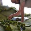
Finally managed to finish this one, with a few stumbles toward the end. I tried out a host of new techniques and materials on this thing and am pretty happy with the result. Another thing I'm fairly happy with is I can now get rid of the ginormous box cluttering up the apartment. The only addition was a set of belts, some engine detailing and some nylon thread static dischargers. So without further ado, I give you the pictures.. The build thread can be found here: http://www.britmodeller.com/forums/index.php?/topic/234940474-trumpeter-132-a-1d/
- 43 replies
-
- 18
-

-
I.A.R. 81c Azur/Frrom 1:32 The IAR 80 was a Romanian World War II low-wing, monoplane, all-metal construction fighter aircraft and ground-attack aircraft. When it first flew, in 1939, it was comparable to most contemporary designs like the German Bf 109E, the British Hawker Hurricane, and the Supermarine Spitfire. However, production problems and lack of available armament delayed entry of the IAR 80 into service until 1941. It was forced to remain in front-line use until 1944, when – even if for some aspects outdated – it still could compete under certain conditions with more modern aircraft such as the Lockheed P-38 Lightning. Work began on the IAR.80 prototype in late 1937, originally with an open cockpit and the 870 hp (649 kW) IAR K14-III C32 engine which was a licensed Gnome-Rhône 14K II Mistral Major. The prototype was completed slowly, and first took to the air in April 1939. Test flights of the prototype were impressive; the aircraft could reach 510 km/h at 4,000 m (317 mph at 13,000 ft), service ceiling of 11,000 m (36,000 ft) with the ability to climb to 5,000 m (16,400 ft) in 6 minutes which was respectable at the time, though not up to the contemporary Supermarine Spitfire or Messerschmitt Bf 109 fighters. In comparison the P.24E was almost 450 kg lighter, yet over 80 km/h slower even though it used the same engine. The IAR.80 also proved to be a delight to fly and highly maneuverable. A number of minor problems turned up during the prototype phase, and were dealt with over the next year. To improve power the design was updated to mount the newer 930 hp (690 kW) C36 version of the K14-III. However this engine was slightly heavier than the C32, which required the fuselage to be stretched to move the center of gravity back into the proper position in relation to the wing. The extra space in the fuselage was put to good use by increasing the size of the fuel tanks to 455 l (100 imp gallons). The wing was also enlarged and the tail was revised to eliminate the bracing struts. Since the space was inserted behind the engine, the cockpit ended up further back on the aircraft. A side effect of this extreme rearward position was that the pilot had even worse forward visibility while taxiing than most other tail-draggers. To address this somewhat, the pilot's seat was raised slightly and a bubble-style canopy was added. The updated prototype was tested competitively against the Heinkel He 112, which had just arrived in Romania as the start of a potentially large order. Although the He 112 was somewhat more modern and much more heavily armed with two machine guns and two 20 mm cannon, the IAR.80 with its considerably more powerful engine completely outclassed it in all other respects. The ARR was impressed and ordered 100 of the new fighters on 18 December 1939. Orders for additional He 112s beyond the original 30 were cancelled. Production of the IAR.80 was to start immediately, although the armament proved to be a serious problem. The prototype had mounted only two Belgian-made Fabrique Nationale 7.92 mm machine guns, a licensed modification of the Browning 30 cal. This armament suite was clearly not heavy enough for combat use, and the production model was supposed to mount six of these guns. The German invasion of Belgium and the Low Countries in 1940 ended the supply of the FN guns, and there was no indigenous machine gun that was suitable for use in aircraft. Lacking armament, production was put on hold. It wasn't until November 1940 when Romania joined the Axis that the Germans eventually allowed the delivery of the guns to resume. As a result the first production IAR.80 didn't roll off the line until January 1941, although the first batch of 20 had been quickly delivered by the middle of February. The new armament supply still wasn't enough to fully equip the aircraft, so the production models only carried four guns. The production models also included new oxygen gear. The initial batch of fighters was well received by the Romanian pilots, but they considered the aircraft underpowered and lacking firepower. In order to address the power issue the aircraft mounted the 960 hp (716 kW) K14-IV C32 engine in the 21st through 50th examples, but there was little they could do about the firepower issue at the time. The final stage in the IAR.80's wartime history was the 81C. This version changed the guns once again, this time to the Mauser MG 151/20 which was replacing the MG FF/M in German service and had just been released for Romanian use. The order for the 81C was placed in May 1942, predating the second order of the 81As. The first order for 100 airframes was delivered, like all of the prior updates to the 81 series, with the centre-line bomb rack removed to be used as fighters. An additional order for 35 was placed in February 1943, and then another 15 in January 1944. These aircraft were primarily to replace losses in earlier models, while production of the Bf 109G ramped up. The Model The kit comes in a very attractive top opening box with an fine painting of an 81c in the foreground and its victim, a damaged P-38 Lightning peeling away. Once you get the tight fitting lid off, you are confronted with a single poly bag filled with five sprues of medium grey styrene, plus separate bags containing the clear styrene sprue, resin parts, etch sheet and decals. On inspection the styrene is very nicely moulded with finely moulded panels lines and details such as the rivets and “screw heads”. There doesn’t appear to be any blemishes or sink marks on any of the parts, but still has the feeling of a limited run kit, in that there are no attachment points on any of the parts, so careful fitting will be the order of the day before hitting the glue. The instruction booklet is very nicely printed in an A5 portrait format, which just feels quality. There is a very handy parts/sprue layout on the first two pages followed by 7 pages for the build. These could be a little clearer as it would be easy to confuse the colour call outs with the parts numbers. Take your time in reading the instructions before building to become acquainted with what’s what. The build naturally begins with the cockpit, which is quite complex and care will need to be taken with the rather fragile looking centre instrument panel support struts which are attached to the forward bulkhead. There is no floor in these aircraft just a pair of foot plates, which along with the seat, forward bulkhead and shoulder height deck that holds the structure together. Details, such as the two piece joystick, four piece rudder bar, (including etched foot straps), lower instrument panel. Main instrument panels, trim wheel and various other controls make up into a very busy looking cockpit. The seat itself is made up of nine parts and is finished off with a set of etched lap and shoulder straps. With the cockpit completed, the insides of the fuselage halves can be detailed with items such as the fire extinguisher, throttle, complete with control rods, and gear retraction lever and painted up accordingly. The cockpit is then attached to one half along with the engine mounting disc, before the fuselage can be closed up. Moving on to the wings, which are provided as a single piece lower and two upper sections. These are joined together and fitted with the machine gun barrels, pitot probe, intake grilles and navigation lights, (for which a 0.8mm hole will need to be drilled into the wingtips before fitting). The flaps and ailerons each consist of upper and lower halves and can be positioned as per the modeller’s wishes. There are two types of flap hinges provided, one set for raised flaps and another set for lowered. The ailerons are fitted with both hinges and mass balances. The completed wing can now be attached to the fuselage. The tailplanes are assembled in much the same way with upper and lower halves for each and with separate rudder and elevators all attached to the rear fuselage. Before moving on, the beautifully detailed gunsight is assembled and fitted to the forward bulkhead of the cockpit before the windscreen and canopy are fitted. The aerial mast is slid through the hole in the windscreen framing and there are clear diagrams to ensure the modeller achieves the correct angle, so be aware. The engine is a model in itself and going by the instructions will be a complex build in which care and patience will be required in spades. Especially as although the instructions are pretty clear, the number of red lines showing different parts positions does make it a mite confusing. The front and rear banks of cylinders come in two halves, which when assembled are joined together, followed by the crankcase and flange ring. The valve rods come in individual or paired parts, which is why the modeller will need to take care on what goes where. To the rear of the engine the intake manifold is assembled from individual pipes attached to the manifold ring before being fitted. For the exhausts the two main parts are in very nicely rendered resin, onto which the individual exhaust manifolds are attached before fitting to the engine. The completed engine is now attached to the mounting ring on the fuselage and encased in the three part cowling, which is then detailed with etched cowl flaps. It’s a shame that such a beautifully detailed engine is all covered up, so I’d imagine some modellers opening up the access panels in the cowl to show it all off. Turning the model over there are quite a few details to add, these include the two piece car intake, the five piece centreline bomb rack and the tail skid. The undercarriage is each made up of single piece main legs/oleos which includes one half of the wheel axle yoke, two piece wheels/tyres and the other half of the axle yoke. Each of the undercarriage bay doors are detailed with individual flange pieces and strengtheners before being fitted to either the undercarriage leg or the wing. The actuator jack and scissor links are then attached to their respective positions. Again, separate clear diagrams show the angles required for the undercarriage legs and doors. The final part to the build is the assembly of the propeller, which is assembled from three separate blades, the back plate and the spinner, then attached to the model Not forgetting the addition of the aerial wire once painting has been completed. Decals The two decal sheets are really well printed, by AVIPRINT of The Czech Republic. Register and opacity are good and there appears to be very little in the way of carrier film. The coloured markings are bright and vivid and have been printed separately from the white decals. The markings are for five aircraft, all in variations of the standard Olive green, over light blue grey and yellow fuselage and cowling bands. The aircraft depicted are:- I.A.R.81-c No.320 Escadrilla 61 Vanatoare, Grupil 6 Vanatoare, Popesti-Leordeni, June 1944 flown by Lt.Av Mircea Dumitrescu, Commander of the squadron. I.A.R.81-c No.323 Escadrilla 61 Vanatoare, Grupil 6 Vanatoare, Popesti-Leordeni, June 1944 flown by Lt.Av Dumitru Baciu. I.A.R.81-c No.369 Escadrilla 61 Vanatoare, Grupil 6 Vanatoare, Popesti-Leordeni, June 1944 flown by Lt.Av Nicolae Limberg. I.A.R.81-c No.448 Escadrilla 67 Vanatoare, Grupil 2 Vanatoare, Miskolc, April 1945. I.A.R.81-c No.446 Escadrilla 67 Vanatoare, Grupil 6 Vanatoare, Gheraesti-Bacau, July 1945 Flown by Adj.Av. Gheorghe Grecu. Conclusion This aircraft, in my view, falls into the familiar but still unusual camps. I certainly knew of the aircraft, but didn’t know much about the genesis of the design and it’s quite successful use in the hands of the Romanian pilots. The kit itself looks to be very nicely produced, and even in its short run format it should build into an interesting and colourful model. The detail is certainly there, yet I’m sure there are those who could do wonders with some additional scratch building. All in all a very nice kit and recommend it highly, with the caveat that you will need to take care in the areas mentioned above. Review sample courtesy of
-
Albatros D.Va (OAW) 1:32 Wingnut Wings The Albatros D.III and D.V's were the most numerous fighter in German Service on the Western front throughout most of 1917 and early 1918. They always suffered from structural weaknesses, most notably with the lower wings which were single spar. This provided insufficient strength to withstand some more extreme manoeuvres, and the lower wings could be torn from the fuselage. The D.Va was an attempt at a strengthened version of the D.V with deliveries beginning in October 1917. Ostdeutsche Albatros Werke received an order for 600 D.Va's in October 1917 and incorporated their own ideas for strengthening into their production aircraft. All of which helped to make the OAW produced D.Va's nearly 100 Kg heavier than the original Albatros built D.V. Nevertheless it soldiered on until the end of the war as the Fokker D.VII gradually (but not completely) replaced it. The latest release from Wingnut Wings comes as a welcome surprise, with a very striking painting of a Jasta 18 'Ravens' D.Va in action against a pair of SE5.a's. The box contains the familiar plastic parts and etched brass from the existing D.Va kit, with new decals and colour schemes. As the differences between the D.Va and D.Va(OAW) are mainly on internal structure, this is perfectly sensible. OAW specific parts such as wheel covers and fuselage lifting handle are also provided to take care of the few differences. The instruction manual is printed in full colour on heavy glossy paper and contains a wealth of information, both on how to build your model, and specific details of the full size aircraft. I particularly like the contemporary black & white photos, as Wingnut Wings seem to come up with ones I have never seen before, and the captions always seem to point out something to add to your personal knowledge store. Nobody does instructions as good as Wingnut Wings, in fact nobody else even comes close. The coloured assembly drawings are clear, with colours also flagged if necessary, and illustrations of complete sub assemblies have helped me to understand an assembly sequence many a time. Sprue A. This holds mostly interior and other delicate parts, and also the D.Va specific ailerons and control column with its aileron cable pick-up from the lower wings. The mouldings are first rate, with all the bulkheads featuring lightening cut outs, and there is no flash or sink marks at all. Sprue B. Here we find the upper and lower wings, tailplanes, and rudder. All are moulded as single parts, i.e. no halves to be joined, which enables very nice sharp trailing edges to be achieved. The wings are very nicely cambered and feature fine rib tapes. [ Anchor holes for the rigging lines are present, which makes me wonder how on earth they can do that on the master mould. Sprue C. A simple clear sprue with three options of windscreen for which ever version you choose. Crystal clear and flawless mouldings. Sprue D. Two are supplied, as they cover all the parts that are required in duplicate, such as guns, wheels, and struts. Also included are the OAW specific wheel covers, as well as the standard Albatros ones. Sprue E. Is for the Mercedes D.IIIa engine, along with a choice of four propellers. Being such a widely used engine, this sprue features in several of Wingnut Wings German kits and several parts are marked as 'not for use'. The detail moulding is superb, the crankcase, rocker arms, and intake manifold being particularly nice. Having built several of these already, I can vouch for the fact that they look stunning when made. The only thing I add is ignition wiring from either thread or fuse wire. Sprue F. Dominating here are the two fuselage halves, which have the finest detail inside and out. All the little brackets, clamps, louvres, and inspection covers are there. Also offered are a choice of a Daimler-Mercedes or Teves & Braun radiator for the upper wing, and various sections of pipes. Photoetch. The small fret offers fretted jackets for the twin Spandaus, which in my opinion are essential in this scale. Plus there is a four point seat harness, gun cover, and cowling retaining strap. Decals. Two A4 sheets provide a very generous amount of upper and lower 5-colour lozenge strips, more than enough for an Albatros, whilst a further A4 sheet contains a large range of rib tapes, with a choice of plain linen, pink, or blue. Impressive. The scheme specific options are printed on one and a half A4 type sheets. A huge range of items are supplied, for the fuselage spirals, tail stripes, badges, spinner rings, etc. Each option seems to have it's own version of the German crosses for the wings & fuselage, and all these are present on the sheets. As usual we have all the instruments as decals, which can be read with a magnifying glass, and my favourites, the propeller manufacturers logos This is as complete a package of decals as you are ever likely to find in a mainstream kit. Colour schemes; A) Albatros D.Va (OAW) 6553/17, Jasta 73, mid 1918 B ) Albatros D.Va (OAW)?, Jasta 18, May 1918 C) Albatros D.Va (OAW), Hermann Leptien, Jasta 63, mid 1918 (7 victories) D) Albatros D.Va (OAW), Hans von Gössel, Jasta 71, mid 1918 (1 victory) E) Albatros D.Va (OAW), Friedrich Ritter von Röth, Jasta 23b, early 1918 (28 victories) Conclusion. Although not a totally new release, this is still very welcome as it does give us another sub variant of the widely used Albatros, and therefore another canvas for the numerous schemes they wore. Wingnut Wings have cleverly provided the colourful boxtop Jasta 18 machine as an option, which as it does not require a natural plywood fuselage should be fairly simple to do. Having already built this kit from the 32009 D.V release, I can confirm that it goes together beautifully and makes a stunning model. It's another box of pure modellers delight. [EDIT] 30/05/2015 Review kit built and posted in Ready For Inspection [/EDIT] Highly Recommended Review sample courtesy of
- 2 replies
-
- 5
-
-
- Alabatros
- D.Va (OAW)
- (and 2 more)
-
Hello, I'm presenting my Special Hobby's A5M4 Claude in 1:32 scale - model represents the machine from Soryu carrier, pilot PO1/c Matsuo Hagiri, summer 1939. The kit contains numerous resin and PE parts, so I did not use any other aftermarkets. Painting was done using Mr. Hobby Super Metallic metalizers and acrylics. Hope you enjoy!
- 12 replies
-
- 10
-
-
Agusta/Westland Lynx HAS-3 1:32 Etched sets With the release of the Revell 1:32 Lynx HAS-3 it was only a matter of time before Eduard released the relevant etched sets for it. The three main sets and one zoom set, come in the standard poly sleeves, and, unfortunately the rather disappointing instructions. Still the etched parts are still superbly produced and provide all that the modeller could possibly want to add to their build, and probably some that they didn’t know they wanted. Whilst the majority of the parts are the same as on their earlier releases for the Mk88 Lynx, there are enough type specific items on the sheets to make them not quite transferable. Lynx HAS-2 Exterior Set – 32347, contains new grilles for the rotor head gear box fairing, panel surrounds, door window frames and handles for the cabin sliding doors, handles for the cockpit doors, and a new Doppler panel. The nose wheel bay benefits from having new sidewalls and bulkheads, while the nosewheel oleo is fitted with hydraulic lines and connecting rods. The cabin machine gun, if fitted is kitted out with new front and rear sights, new barrel which will need to be carefully rolled to shape and a new ammunition box cradle. The main wheels are fitted with new brake discs, scissor links and hydraulic pipework. There are also new grilles for the tail cone and vertical tail, hydraulic lines and root fittings for the main and tail rotors, lifting eye for the rotor head, sensor faces, windscreen wipers and the grille in front of the windscreen. The torpedoes receive new parts for both the tail and nose sections. Lynx Mk88 Seat Belts – 32763. As this sets name suggests it provides the modeller with a full set of seat belts for all the seats in the kit. The belts and fitting are pre painted, a different colour to the earlier release, and do really look the part, although I’m sure a bit of dirt will make them look even more realistic. In addition to the seat belts the set also includes the seat frame and other fittings for each of the pilots seats. These are not pre-painted, but do provide that bit of extra detail that’s need in this scale. Lynx Mk88 Interior – 32765. This set is slightly different in that one of the two sheets of etched brass is not only pre-painted, but self adhesive. The parts include the instrument panel with a backing with the instrument painted on. At least in this set the instrument is completely different to the earlier release, showing the larger panel of this mark. When joined, but before fitting to the kit, it might be an idea to add a drop of Klear or Aqua gloss to each instrument to depict the glass face. Also included on the self adhesive sheet are the upper and central consoles, warning light bar, circuit breakers, radar screen, and auxiliary flight instruments for the cockpit and the black and yellow warning strip for around the cabin door window frames, placards and emergency release handle, also in black and yellow. The larger unpainted sheet contains parts to enhance the actual frames for the cockpit bulkhead and cabin doors, cockpit centre console sides, instrument panel coaming, cabin door cards, and other detail parts for both the cabin and the cockpit including such as the cyclic and collective control sticks, upper console and upper glass frame. Lynx Mk88 Interior Zoom Set – 33120. This is the much simplified set for those modeller who don’t want to add too much to their model, but just add that little extra detail to enhance the completed model. The set includes just one sheet contains all the parts that are on the pre-painted, self adhesive sheet mentioned above. Conclusion As with the earlier Mk88 kit, the Revell Lynx HAS-3 is a great kit, which can still be greatly enhanced with the addition of some or all of these sets are certain items that are lacking, due mainly to the limitations of the injection moulding process. As with these types of aftermarket sets some parts are easier to add than others, but with patience and a steady hand a superb model can be built. Review sample courtesy of Review sample courtesy of
-
Ok so here is my Trumpeter BF109F - a model I have been looking at but shying away from making for 12 months! I finally plucked up the courage to do it in a mottled scheme and indeed it is the first time I have done the mottling thing so its far from perfect so please go easy on me! It took me 5 goes to get it to a stage where I was reasonably happy with it. So i build it OOB with no extras and I used Mr Color paints which are my new favourite and ProModeller washes. The kit itself was a real joy to build and I will certainly do more from Trumpeter. The scheme I chose is unusual I think and I did get some advice from BM - whether the mottling is correct for the wings is open to debate but I didn't get 'hung up' on this as I wanted to practice my mottling. Having looked at the photo's I realise there are a couple of small jobs to finish on it but otherwise it is one of my most enjoyable builds this year Chris
-
Hawker Hunter FGA-9/Mk-58 Revell 1/32 History The Hawker Hunter FGA 9 was the RAF's main close support or ground attack aircraft during the 1960s, having replaced the de Havilland Venom FB.4. The Hunter was chosen for the role after competitive evaluation trials that were carried in Aden in 1958. At first the contest was seen as being between the Hunting-Percival Jet Provost and the Folland Gnat, both in use as RAF training aircraft, but the Hunter F.6 was added to the contest, and easily outclassed its competitors. In 1958 Hawkers received an order to convert forty F.6s to the new FGA.9 standard. This was followed by five more contracts to convert a total of eighty eight aircraft, for a total of 128 aircraft. The F.G.A.9 had a stronger wing than the F.6, allowing it to carry a wider range of stores. The inner pylon could carry a 230-gallon drop tank (with an extra strut for support), but required a cut-out to be made in the flaps for clearance, two 25lb practice bombs, one 500lb or 1000lb bomb, up to 6 3in rockets or a battery carrying 24 or 37 two-inch. The outer pylon could be replaced by four Mk 12 rocket rails, each of which could carry three or four 3in rockets. In 1967 this was replaced by the 68mm SNEB rocket pod, which carried eighteen individual rockets. The FGA.9 also carried extra oxygen, improved cockpit ventilation and cooling (to cope with the high temperatures in the areas it was expected to operate in) and a tail landing parachute to help on smaller Middle Eastern airfields. The first F.G.A.9 made its maiden flight on 3 July 1959, and entered service with RAF Strike Command (the former Fighter Command) in 1960-61, joining No.8 Squadron at Khormaksar (Aden) in January 1960. No.208 received the type in March 1960 and used it from Kenya. No.43 received the FGA.9 at home then took it to Cyprus in June 1961. No.20 Squadron received the type at Singapore then used it during the Indonesian crisis of the mid 1960s. At home Nos.1 and 54 Squadrons received the FGA.9 in 1961. The FGA.9 began to be phased out towards the end of the 1960s. The last few squadrons to use it as a front line aircraft were No.1, which transferred to the Harrier from July 1969, No.54 which was disbanded then reformed as a Phantom squadron in September 1969 and No.8 Squadron, which lost its aircraft on its return from the Gulf in 1971. The aircraft was then used with a number of training units before finally retiring from that role in 1980. The FGA.9 was the basis of a large number of export versions of the Hunter, while twelve were sold directly to Rhodesia in 1963. The Swiss meanwhile had taken delivery of their FGA.9 equivalents, the Mk58 in 1963 having ordered 12 modified Mk.6 aircraft and 88 new builds. Swiss Hunters were operated as interceptors, with a secondary ground-attack role; the outboard wing pylons were modified to carry two AIM-9 Sidewinder air-to-air missiles. In the ground-attack role, the Swiss Air Force maintained an arsenal of conventional iron bombs, a number of compatible napalm bombs were also maintained for intended use by the Hunters. In the interceptor role, the Hunters were supplemented by a surface to air missile (SAM) defence system also procured from the United Kingdom, based on the Bristol Bloodhound. A portion of the Hunter fleet was permanently placed in reserve as "sleeper squadrons", housed in remote mountain-side hangars. It was planned that in a large-scale conflict, these aircraft would fly from adjacent highways, using them as improvised runways. By 1975, plans were laid to replace the Hunter in the air-to-air role with a more modern fighter aircraft, the Northrop F-5E Tiger II. The Hunter remained in a key role within the Swiss Air Force; like the RAF's Hunter fleet, the type transitioned to become the country's primary ground attack platform, replacing the Venom. While the Swiss Hunters already had more armament options than the RAF aircraft, being cleared to carry Oerlikon 80 mm rockets instead of the elderly 3-inch rockets used by the RAF, to carry bombs from both inner and outer pylons and to launch AIM-9 Sidewinder air-to-air missiles, the change to a primary air-to-ground role resulted in the Hunter 80 upgrade, adding chaff/flare dispensers, BL755 cluster bombs and the ability to carry AGM-65 Maverick missiles. The Patrouille Suisse flight demonstration team were prominent fliers of the Hawker Hunter for several decades. Squadron aircraft were fitted with smoke generators on the engine exhausts and, later on, were painted in a distinctive red-and-white livery. The group officially formed on 22 August 1964, and used the Hunter as its display aircraft until it was withdrawn from use in 1994. The Model The big Hunter FGA.9 was originally released by Revell in 1998 and whilst there are rumours on how it didn’t sell as well as was predicted, it still seems to be a popular kit, particularly since there are a number of conversion and aftermarket sets available to make other versions and improve the kit ones. Revell have kindly decided to re-release this as it was getting relatively hard to find, although I know a few stashes where quite a few are held. The kit comes in the same style of top opening box that the original did, but with a slightly different box art showing a very nice artists representation of the aircraft “flying” out of the box and a photograph of a Swiss aircraft in the bottom right hand corner. Inside, the two sets of sprues, standard hunter parts and FGA.9 specific parts, are contained in large poly bags. This at least means that any parts that come away from the sprues are safe, even if there is more likelihood of the parts being damaged. Fortunately the clear sprue is held in a separate poly bag. All told there are six quite large sprues of light grey styrene and the one of clear. The moulds still appear very fresh as there is no sign of flash or other imperfections. Although some of the details do appear a little soft, particularly in the cockpit. The external details such as panel lines and fasteners are really finely done, some may say too fine, but the Hunter was a clean looking aircraft with good fitting panels, well, certainly the GA-11’s I used to see a lot of when based down at RNAS Yeovilton were. Now while I’m sure many people know this kit intimately this review will be written as if it’s a completely new release for those who haven’t had the opportunity to see it before. The build begins with the cockpit and the ejection seat in particular. The instructions give the modeller a choice of two seats, depending on which version of the Hunter they intend to build, but in reality it looks like the only difference is in the colour scheme and stencils used. Each seat consists of the seat pan, back rest, and seat squab to which the main gun frame and head box is attached and finished off with the addition of the central seat pan firing handle. As you’d expect the instrument panels are different between variants, but since the details are quite soft they would be better replaced with something from the likes of Airscale and their excellent instrument and bezel packs. The instrument panel, rudder pedals, forward bulkhead and joystick are then assembled to the cockpit floor with the side consoles moulded integrally. The ejection gun unit is then fitted followed by the ejection seat itself, along with the rear bulkhead. The completed cockpit assembly is then sandwiched between the two nose fuselage halves. To this main assembly the cockpit coaming is attached along with the gun sight and gunsight glass. The nose wheel bay is then fitted with the nose wheel leg and its retraction jack and attached to the inside the nose wheel panel, which is then affixed to the underside of the nose assembly. Moving on, the front engine fan disk is fitted to the two halves of internal intake ducts, this assembly is then attached to the lower portion of the intakes along with the forward duct sides after which the upper intake section can be added, and for the RAF version a pair of sensor fins. The complete intake assembly is then added to the rear of the nose assembly. The nose cone can then be filled with the appropriate weight and attached to the nose. With the appropriate holes opened up in the lower wing sections the wing halves can be glued together. The optionally positioned flaps are then attached, as are the wing tips, navigation lights and leading edge dog tooth extensions. The rear fuselage also requires certain holes to be opened up if the Swiss version is to be built. The two halves can then be joined together. The engine exhaust nozzle is now assembled between the two rear tail cone halves and the upper and lower sections of the horizontal tailplanes are glued together allowing the main structures to be assembled. The nose assembly is joined to the rear fuselage assembly followed by the tail cone, tailplanes and wings. Lastly the upper fuselage spine is attached, and runs from just behind the cockpit to the spine join just in line with the wing trailing edges. The already assembled nose undercarriage leg is fitted with the nose wheel, moulded in two halves, and the completed with the fitting of the other half of the axle yoke. The rear bay door is then attached to the fuselage and joined to the nose wheel leg by two struts; the front bay door is then attached to the front of the bay. Too pose the doors closed you will need to remove the retention lugs before fitting to the bay. The main wheels are each made up of two halves, which when joined together are completed by the addition of the inner hub. This assembly is then attached to the main oleo axle along with the separate scissor link and the upper bay door, which has to be separated from the lower door as it is moulded as one piece to aid fitting if posed in the closed position. The middle outer door is then attached to the wing and connected to the oleo by two struts, then the lower bay door is attached the two legs of the middle door. The completed main legs are then fitted into their respective positions followed by the inner bay door and its associated actuator jack. Final fitting out of the model includes the attachment of the airbrake, in either open or closed position, tail bumper, windscreen and canopy, alternative aerials and sensors, depending on which version is being built, rear bullet fairing tip, and the optional types of cannon link chute fairings. Revell have provided a pair of 230gal and two 100gal drop tanks, each of which are made up of two halves, with the 100gal tanks also having two stabilising fins attached to the rear. Each pylon is also in two halves and when attached the 230 gal tanks are fitted with a support strut. The kit also has the option of having two 68mm rocket pods fitted in place of the 100 gal tanks on the outboard pylon. These are assembled again from two halves with a separate nose cone. For the Swiss version the kit provides for an extra pylon, practice bomb unit, 675ltr drop tanks, two Maverick missiles and different cannon muzzles. Decals The single large decal sheet provides a complete stencil set for each version of the aircraft plus all those required for the different tanks and weapons. The markings provided are for the following:- Hunter FGA.9 of No.1 Squadron, Royal Air Force, West Raynahm, England, September 1963. Hunter F.58, Fliegerstaffel 21, Swiss Air Force, Emmen Air Base, March 1994. Conclusion It’s very nice to see this kit re-released and it’s still a fabulous looking kit. Not being overly complex it shouldn’t take too much to make a good looking model out of it. I have heard there may be fit problems in some areas, but with a bit of care and patience I’m sure they won’t be too bad. It will certainly be an impressive model for any collection. Plus the fact that so there are so many lovely aftermarket sets available the world is truly your cuttlefish. Highly recommended. Revell model kits are available from all good toy and model retailers. For further information visit or
-
Roland C.IIa Late 1:32 Wingnut Wings After initially building Albatros two seaters under licence, the Roland company began to look at producing an aircraft of their own design. A lot of effort went in to creating as smooth and low drag a shape as possible, eliminating the cabane struts by mounting the top wing directly on to the top of the fuselage. The fuselage itself was an innovative monocoque construction of layers of thin plywood strips laid over a mould in a criss-cross pattern. Two halves were made (just like a kit!) and joined together around an interior framework. The join line was covered with tape and the whole unit covered with doped on fabric, creating a fuselage with an excellent strength to weight ratio. Nicknamed 'Walfisch' (Whale) the C.II proved to be significantly faster than most other two seaters, and the majority of single seat fighters. View above and behind was excellent, but downward was poor due to the positioning of the pilot high up near the wings, and made the aircraft difficult to land. The tail assembly also suffered from some lack of airflow due to the blanking effect of the fuselage. However, as long as it held on to it's speed advantage it was able to carry out its reconnaissance tasks in relative safety. The C.II and later C.IIa served from the spring of 1916 until mid 1917, latterly in an escort role or employed on troop support/ground attack. Once removed from front line service most Rolands were only to be found in use with training units. An attractive aircraft, many will be familiar with the vintage 1/72 Airfix kit, either in its single issue or 'Dog Fight Double' with wonderful artwork showing it slugging it out with an RE.8 (and what a rare treat it was those days to afford to buy one!). Blue Max and Eduard have both issued the Roland in 1/48 and such is my liking for it that I have examples of both in the stash. Joining them now are two releases from Wingnut Wings in 1/32 covering the 'early' and 'late' production versions. Principle differences were that the late versions had strengthened wings, a forward firing 1MG 08 Spandau, aileron control rods and tubes routed through the wings, a stick type control column, and most noticeably on the very late examples, an enlarged fin. The Kit. The 'late' edition of the kit has been received for review at Britmodeller. Arriving in it's classy black, silver edged box with Steve Anderson's evocative painting of a pair of C.IIa's high up over the western front, this one has been eagerly awaited by many. More than usual the box has a very weighty feel, and no wonder, because when you lift the lid it is absolutely packed with sprues. We already know that Wingnut Wings never disappoint, and anticipation is by now running at fever pitch, so lets take a look! The instruction manual is the familiar fully illustrated high quality document that Wingnut Wings always provide. The 28 pages offer a short write up of the subject, a parts map, 12 construction stages, 5 finishing options, and plenty of original period photographs. Think less 'construction drawings' and more 'reference document to retain after the model is built'. I have never seen better instructions than those provided by Wingnut Wings. And they back them up on their website with more period photographs, hints & tips, and any amendments. Sprue A. Covers the interior frameworks and fittings, all delicately moulded with fine detail from parts such as the dimpled and creased seat cushion, through the ultra fine matrix pattern on the radiators, to the finely fretted framework of the bulkheads. Every part is perfectly formed and free from any flash or sink marks. Sprue B. A real eye catcher this one, holding the fuselage halves and sundry fittings. The lovely shape of the fuselage is captured beautifully, and features cut out louvres on the nose, various other minor 'lumps & bumps' and louvres and vents that you may need to carefully remove depending upon which finishing option you choose. The tail fin will need to be fitted from a choice of the early or later and larger option. On the inside the angled plywood construction is represented and there are a selection of flashed over holes that you may need to drill out according to your chosen option. Several parts on this sprue are marked as not for use, but still the moulding quality of them is exquisite. Details; Sprue C. Two are provided, with the side window and windscreen options. Sprue D. Another double set, these cover the wheels, tail planes, inter plane struts, and smaller parts needed in duplicate. Again some are marked as not for use. Sprue E. Here we have the engine, a Daimler-Mercedes D.III. I have built several of these already as it is common to several other Wingnuts kits. It builds up easily and looks great when all the natural metal parts are finished in Alclad. The only thing I ever add is ignition wiring from the magnetos to the plugs, using fine copper wire. As indicated in the instructions, only two of the props are appropriate to this version - the Axial and the Wolff. Sprues G and G3. These are generic sprues also found in other Wingnut Wings kits. 'G' holds a small set of Parabellum options and ammo drums, whilst G3 is a 'general fittings' set. As well as more props there are various Recce cameras, ladders, flare racks and pistols, radios, a first aid box, and other useful bits and bobs. A lot of this can go to your spares box or be used in a diorama. It is the sort of really useful stuff that you just won't find anywhere else and is a definite bonus to buying this kit. Sprue H. One of two sprues unique to the 'late' version of this kit, this holds the wings, Spandau & roll hoop, bomb rack, and a couple of panels. The early wings had wire trailing edges (which would have produced a 'scalloped' effect) but the late wings did not. Such is Wingnut wings attention to detail that they produced a completely new tool to replicate this, and also moulded the control linkages in relief. Detail of the finely moulded bomb rack; Sprue I. The other one unique to this release. Here we have the cockpit floor, instrument panel, two more choices of exhaust pipes, the 'late' tailfin, and a small selection of levers, pulleys, etc. Photo etch. Pilots and Observers seatbelts, gunsights and jackets for the machine guns. Decals. Printed by Cartograf on an A4 sized sheet all the options are covered, with a section common to all and largely consisting of instrument faces, stencils etc. Various Eisenkreuz are provided with and without white square backgrounds according to which option you choose. A nice touch is that option A is provided with a choice of black or red fuselage bands, as it is not clear from the period black & white photographs which were used. As the instructions also include a photo you can make your own interpretation. The printing is beautifully sharp, and is especially impressive on the smaller stencils. Options. Option A, Roland C.IIa, "White 7", Kasta 2, Kagohl 1, Late 1916 - Early 1917. Option B, Roland C.IIa, (Li) "Black III", Vfw Hesse, Schusta 13, Early 1917. Option C, Roland C.IIa (Li) 3645/16, Hans Joachim von Hippel (1 victory), Beobachter Schule Cöln, Early - mid 1917. Option D, Roland C.IIa "White 21", Otto Burgermeister, Kasta 21, Kagohl IV, November-December 1916. Option E, Roland C.IIa "circles", Kagohl II?, late 1916 - Early 1917. Conclusion. I'm sure that the Roland C.II has been eagerly awaited by many of us, certainly I have been really looking forward it. Iti s well up to the high standards that Wingnut Wings have set and I have no doubt that it will fit together beautifully and look stunning when finished. One big advantage is that the wing arrangement should make it easy to build, in that both sets fit right on the fuselage with only two interplane struts. For a biplane, it hardly gets easier than this. There is a little bit of rigging, but it is minimal and simple. Given the attractiveness of the aircraft and what looks to be an uncomplicated assembly job, I can see this one becoming one of Wingnut Wings best sellers. Again there can be only one verdict; Highly Recommended Review sample courtesy of
-
 This is another project which I will be starting as a fill in project when my 2 main projects are drying as this model will be painted using Revell Enamel paints which I have already got for a previous Red Arrow I bought but which was too small. Box Art Kit Sprues The kit comes on 3 or more sprues, all made from red plastic except from some clear parts. However they all seem quite large. More progress when I actually open the bags and start working on the kit.
- 62 replies
-
- 1
-
-
- Hawk
- Red Arrows
- (and 2 more)
-
I've been itching to make a start on this, but have needed to get the ongoing pile of builds on my workbench reduced. At last I've only got 5 (!) other things on the go so feel justified in getting this beauty under way. It is one of Wingnut Wings superlative kits, I always find them a complete joy to build and this one looks as good as ever. The Sopwith Snipe was a development of the famous Camel, and arrived on the western front in the last few weeks of WW.1, giving a good account of itself in the few combats it encountered. It went on to serve in the post war RAF into the 'silver wings' era. A full review of the kit can be found HERE I've decided to go for a silver doped machine. I like the 56 Squadron colour scheme but am less keen on it having an overall silver doped finish, including all the forward panels and cowling. I think I will do the 17 Sqn machine as it has bare metal panels and cowl, which I prefer. I have started by removing all the components needed for the cockpit interior and fuselage, cleaning off any moulding lugs and faint seam lines. Everything then received a coat of Halfords grey primer from the spray can. I get together as many parts as I can that will need a wood or clear doped linen finish, which includes the prop and the struts. These were all sprayed in one session with Tamiya XF-55 Deck Tan, and have since had a coat of Johnsons Klear brushed on them. Parts at the bottom of the picture will have various other coloured finishes, but have been primed. The Instrument panel has a choice of wood or black finish, I went for black as there is already a lot of wood in the cockpit, and those two large pieces on its lower half are the ammo tanks and need painting in aluminium. It is vitally important with any biplane kits to make sure you get the correct struts in the correct places, or the wing alignment will go out. I have already removed the struts from the sprues as I want to do them with the rest of the woodwork. (Only the post war options need the struts in wood finish, war time machines had them painted grey). So to keep them all identified until needed I bag them up in pairs and label each bag with part numbers. When I paint them they are held in pegs and placed on their bags whilst drying, and popped inside when dry. Next the struts and other parts in XF-55 will get brushed coats of artists oils on them. Next update when I've got some of that done..... John
-
US 250lb Bombs 1:32 Brassin This set of two US 250lb M-57 bombs from Brassin are pretty much scaled up versions of the 1:48 set reviewed HERE. Due to the increase in size these bombs there is a little extra detail provided. The casting is just as well done, with some very fine details, such as the bomb lugs, with both US and British styles, (one or two lugs), moulded onto the bomb casing. Assembly is nice and simple, as once removed from the casting blocks and cleaned up it’s just a matter of fitting the etched “wire” into the rear of the casing, attaching the rear arming vane, sliding the box tail into place and attaching the front arming vane. Then it’s just a matter of painting, adding the supplied decals, and weathering. Since they were introduced in 1943 and weren’t removed from the weapons list until the 1960’s they can be used on virtually any WWII/Korean/Vietnam War aircraft, although with something like a Skyraider you will need to purchase quite a few two bomb sets. Conclusion As is becoming the norm for Brassin these bombs are really well manufactured. Great moulding, good attention to detail and since they were so widely used, they will make an excellent addition to any modellers armoury. Highly recommended Review sample courtesy of
-
Messerschmitt Me109G WGr.21. Rocket Pods Brassin 1:32 Brassin Set 632034 Just when I thought that Eduard couldn’t produce anything else for the Revell 1:32 Me109G kit they go and release this set of WGr.21 Rocket Pods. Packaged in a clear styrene bubble pack with a layer of protecting foam, the set provides parts for two rocket pods, one for each wing. Each pod is made up of the tube, rocket and aerodynamic nose cone, plus the bracing stays. The cast details are really well done, being very fine and realistic, even to the point that Eduard make a note that the seam down the side of each tube must not be sanded away as it is the weld seam and is meant to be there. The set is easy to use, it’s just a matter of removing the parts from the casting blocks, a quick clean up with a sanding sponge, then assemble. Each rocket has a PE base glued to the rocket motor end, slide the rocket into the tube then attach two PE rings to the rear of the tube, and the optional aerodynamic nose cone is then attached. The suspension lug is then fitted to the midpoint of the tube and the bracing struts applied to their respective positions. A brass template is provided to scribe the lower wing panels and drill the holes for the struts and suspension hook. With this done the PE suspension hook and plate are attached to the wing along with the pods themselves, followed by the PE wire running from the rear of the pod, down the rear left inboard strut and into the wing, job done. Conclusion If you want to add extra weaponry to the lovely Revell 1:32 G-6/G-10 then this is certainly one way to go. With the beautifully moulded details it will certainly enhance an already great looking kit. Highly recommended Review sample courtesy of
-
F4U-1 Corsair Engine Set Brassin 1:32 Engine Set (632032) It seems that now Brassin have just about done every conceivable upgrade for the Revell 1:32 Me109 they now have time to turn their attention to the Tamiya 1:32 Corsair, with the release of this engine set. As with the majority of larger Brassin sets, this one comes in a cardboard box inside of which are four bags of resin parts, with five of the larger resin parts loose and one sheets of etched brass/nickel. These are all very well protected by blocks of foam. The large instruction sheet is very well laid out clear, and certainly a big improvement on the standard instruction sheets. A lot of the parts are very fragile and care will be needed when removing them from the moulding blocks. The larger parts look pretty easy to remove and clean up as they are only attached to the moulding block on one edge. The detail on the completed engine is such that it could easily be assembled and displayed as a model in its own right, although a scratch built engine stand will be required. There are 81 resin parts, in a mixture of medium and dark greys. The detail on the resin parts is pin sharp, and with a good depth, which a dark wash will help bring out. The eighteen individual cylinders, nine for each bank, are attached to what I guess could be called the engine block ensuring that the cylinder fitted to the top centre of the front bank is the correct item. Each cylinder is then fitted with a spark plug on the forward face. The intake manifold is then attached to the rear, making sure that the ends meet the cylinder intakes correctly. The etched wiring harness is then attached from the front and the “leads” fixed each of the spark plugs. The fastener ring is then fitted, followed by the reduction gearbox case, which has been moulded with the two magnetos and spark advance unit fitted. In addition to the provided PE, a lot of the other pipework and wiring has to be provided by the modeller, but the instructions give detailed information of the thickness, length and position of each part. Once the wiring is complete the cooling gill part is affixed to the rear of the engine, followed by the exhaust manifolds, the lower two of which need to be sourced from the kit, whilst at the front, the cowling nose section is attached. Finally to display the engine off, the two resin cowling side panels are fitted out with strengthening/ fastener strips and either left off or attached at the hinge points and a suitable length of rod used to prop them open. As shown in the picture taken from the Eduard store below. Conclusion The Tamiya F-4U Corsair is already an outstanding kit with very few problems or vices that haven’t already been fixed by other aftermarket companies. The kit already has a beautifully detailed engine so I do wonder whether this engine set will sell that well, but I’d imagine Eduard have thought of that. It is a fantastic piece of moulding with an amazing level of detail which as stated above, might be better being shown off in its own right or as part of a diorama. Highly recommended Review sample courtesy of
-
Messerschmitt Me-109 G-6 Revell 1:32 The G series, or "Gustav", was introduced in mid-1942. Its initial variants (G-1 through G-4) differed only in minor details from the Bf 109F, most notably in the more powerful 1,455 HP DB 605 engine. Odd numbered variants were built as high-altitude fighters with a pressurized cockpit and GM-1 boost, while even numbered variants were non-pressurized, air superiority fighters and fighter-bombers. Long-range photo-reconnaissance variants also existed. The later G series (G-5 through G-14) was produced in a multitude of variants, with uprated armament and provision for a number of kits of pre-packaged, generally factory- installed parts known as Umrüst-Bausätze (usually contracted to Umbau) and adding a "/U" suffix to the aircraft designation when installed. Field kits known as Rüstsätze were also available for the G-series but those did not change the aircraft designation.) By early 1944 tactical requirements resulted in the addition of MW-50 water injection boost and high-performance superchargers, boosting engine output to 1,800–2,000 PS (1,775-1,973 HP). From early 1944 a number of G-2s, G-3s, G-4s and G-6s were converted to two seat trainers, known as the G-12. An instructor's cockpit was added behind the original cockpit and both were covered by an elongated, glazed canopy. The so-called Rüstsätze field modification kits and Umrüst-Bausätze factory conversion kits were part of a system promulgated by the RLM as a whole, throughout the German military aviation industry, with each airframe type number having its own set of "/R" and/or "/U" numbered designations for such upgrade packages. The Model Revell last released a new tool Me-109G-6 back in 1987 which was an ok kit for its day. Now they have released a brand new tooling of this great aircraft and boy does it look good. The kit unfortunately comes in the standard end opening and slightly feeble box with the parts protected in a couple of poly bags. The kit comes on three large and eleven small sprues of light grey styrene as well as two sprues of clear parts. All the parts appear very well moulded with only a very small amount of flash on a couple of the smaller sprues but quite a few moulding pips throughout. Detail is very nicely done with fine recessed panel lines, raised areas where necessary, finely executed rivets and fasteners and restrained detailing on the fabric covered control surfaces. The styrene is quite soft so be careful when removing parts and cleaning them up. Any ejection pin marks are thoughtfully placed in concealed areas. There are small sink marks in each of the propeller blades near the roots, nothing a small amount of putty and a quick swipe with a sanding stick can’t sort out. Construction starts with the cockpit floor, onto which the rudder pedals and foot rests are fitted. Then there is a choice to make on which cannon the aircraft is fitted with, and therefore which breech cover to build. The instructions state that the Early version was armed with the Mk108 30mm cannon and the Late version was armed with the MG-151/20 20mm cannon. Now from research it looks like it should be the other way round so it may be an idea to just check before building your particular aircraft you are modelling. With the choice made, the two halves of the respective breech cover are joined and fitted to the front of the cockpit floor, onto which the joystick is also attached. The cockpit is further built up with the attachment of the pilot’s seat to the rear bulkhead. The pilots harness is pre-moulded onto the seat pan and the bulkhead, with the bulkhead ones being slightly too short and will need to be lengthened or replaced completely with aftermarket items. Rather than having parts moulded onto the insides of the fuselage halves Revell have gone for separate panels for the cockpit sides onto which further parts are added. On the starboard side the clear part that represents the fuel feed pipe is to be masked off before painting so that the inspection tube is left clear, beneath the fuel pipe the fuel pump is fitted. On the port side there are a pair of trim wheels and control runs attached. The instruments dials for the panel are in decal form but with some softener/setting solutions they should settle down ok onto the individual bezels. There is another Early/Late option when it comes to fitting the gun sight which is fitted to the top right of centre on the instrument panel. The cockpits side panels and instrument panel are then attached together with the cockpit floor and rear bulkhead creating a neat looking tub. Underneath the tub the wing spar is attached, whilst on top the rear upper bulkhead is fitted, with a choice of early or late depending on the position of the battery box. With the cockpit complete several other assemblies need to be built up before the fuselage can be closed up. The tail wheel has optional long and short struts as well as different fairings, depending on which version is being built. This also goes for the upper nose cowling with alternative parts, both of which need to have the machine gun muzzles fitted from the inside before attaching to the fuselage. The engine exhaust stacks also need to be fitted from the inside pre painted and masked of before full painting commences. The exhausts are a little bit disappointing in that they are solid and will need some very careful opening up due to their shape. There’s bound to be some aftermarket items released soon to replace these. Once the cockpit tub, propeller shaft, tailwheel and under nose radiator mount are fitted the fuselage can be closed up. The three nose panels are then fitted with an alternative panel for the starboard side. The two piece carburettor intake on the port side is then fitted along with the cowl bulges, again with alternative parts for each version. Under the nose the two radiator grilles are fitted onto their mounting points before the radiator cover is fitted. The wing radiator grilles are attached to the upper inner wing panels which are then attached to the wing spar. Each main undercarriage bay is has the roof part moulded into the inner panels whilst the bay walls are made up of three separate parts. The one piece lower wing panel is then fitted to the upper inner wing panels and spar. While the model is upside down the two wing radiators have the forward intake lips added and two panels are fitted to the centre fuselage. With the model the right side up the upper outer wing panels are attached and the vertical tail unit is fitted, the modeller has the option of short or tall tails depending on which version is being modelled along with the relevant rudders. The rudder trim actuator is then attached to the starboard side of the fin and the horizontal tail assemblies are, with option moving elevators are fitted. The model comes with the option of having the flaps posed up or down with each section being made up of upper and lower halves as do the ailerons. The inner and outer flaps of each wing are attached as per the modellers wishes after which the ailerons can be fitted. The leading edge slats can also be posed open or closed, but being spring loaded they would normally be deployed on the ground. The main undercarriage legs are each made up of an inner and outer oleo parts onto which the axle unit is attached along with the scissor links and a small link near the top of the inner oleo. The main door is then attached to the oleo. There are two types of main wheels and tyres, again depending on which version is being built. Each tyre is in two halves into which the inner and outer hubs are fitted. The details are quite nice, one with radial tread and one with a block tread, but these may get a little lost with having to sand the seam around the tyre unless fitted well. With the wheels assembled they can be fitted to the axles. The two part tail wheel is then fitted to its yoke. Next in the build sequence is the assembly of the drop tank. Whilst he details on the tank are quite good it does seem a little pointy in the nose area and should be blunter. This may be rectified with a little surgery or sanding but most people will be able to live with it. The completed drop tank is then fitted to the adaptor plate and the four stays are fitted. The whole assembly is then fitted to the fuselage centreline. Depending on the version being built there are a number of different parts to be fitted before the canopy can be fitted. There are two types of canopy, an early framed type with separate rear section and a single piece Erla Haube clear view canopy. The windscreen comes with separate armoured screen which would be best “glued” with a drop of Klear or similar. With the aerial masts fitted to the rear of the canopies the relevant armoured plate can be fitted internally along with the locking handle. If the canopies are to be positioned open there are two blocks on the starboard cockpit side panel to provide a good strong joint. The propeller is now assembled out of the backplate, three individual blades, internal blade clamp and the boss. Unfortunately the join between the backplate and boss isn’t at a natural panel line on the real aircraft so will need to be carefully filled and sanded. The propeller assembly is then fitted onto the propeller shaft. With the addition of the pitot probe and underwing aerial for the late version, all that needs to be done is paint and adding a stretched sprue aerial wire for the model to be complete. Decals The decal sheet is printed in Italy for Revell, so presumably by Cartograph, although they don’t look up to the usual standard. They are well printed though, in good register and nicely opaque with very little carrier film except in the white outline crosses and the kill markings. The decals are quite matt in appearance but should settle down well with the appropriate solutions. There is only one option for each version and these depict the following:- • Bf-109G-6 W.Nr. 160717, Stab II/JG-51, Rumania 1944 flown by Hauptman Karl Rammelt • Bf-109G-6 W.Nr. 411960, Stab III/JG-5, Gossen May 1945, flown by Hauptman Franz Dorr. Conclusion This is a very nice kit and while there a few little inaccuracies I’m sure it will be a very enjoyable build and from what I’ve heard the part fitment is very good. Apparently this kit can be easily modified into a G-14 variant, but you have to resarch this yourself. Revell these days seem to excel in producing great large scale kits at a very affordable price, and this one is no different. It doesn’t matter that it doesn’t come with all the bells and whistles as it isn’t made for the experienced modeller, even though I’m sure they’d love this as a nice quickish build. This mark is in my opinion the best looking of the Me-109 series and a model of which I can highly recommend. Revell model kits are available from all good toy and model retailers. For further information visit