Search the Community
Showing results for tags '1:32'.
-
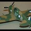
I.A.R. 80-A Special Hobby 1:32 The IAR 80 was a Romanian World War II low-wing, monoplane, all-metal construction fighter aircraft and ground-attack aircraft. When it first flew, in 1939, it was comparable to most contemporary designs like the German Bf 109E, the British Hawker Hurricane, and the Supermarine Spitfire. However, production problems and lack of available armament delayed entry of the IAR 80 into service until 1941. It was forced to remain in front-line use until 1944, when – even if for some aspects outdated – it still could compete under certain conditions with more modern aircraft such as the Lockheed P-38 Lightning. Work began on the IAR.80 prototype in late 1937, originally with an open cockpit and the 870 hp (649 kW) IAR K14-III C32 engine which was a licensed Gnome-Rhône 14K II Mistral Major. The prototype was completed slowly, and first took to the air in April 1939. Test flights of the prototype were impressive; the aircraft could reach 510 km/h at 4,000 m (317 mph at 13,000 ft), service ceiling of 11,000 m (36,000 ft) with the ability to climb to 5,000 m (16,400 ft) in 6 minutes which was respectable at the time, though not up to the contemporary Supermarine Spitfire or Messerschmitt Bf 109 fighters. In comparison the P.24E was almost 450 kg lighter, yet over 80 km/h slower even though it used the same engine. The IAR.80 also proved to be a delight to fly and highly manoeuvrable. A number of minor problems turned up during the prototype phase, and were dealt with over the next year. To improve power the design was updated to mount the newer 930 hp (690 kW) C36 version of the K14-III. However this engine was slightly heavier than the C32, which required the fuselage to be stretched to move the center of gravity back into the proper position in relation to the wing. The extra space in the fuselage was put to good use by increasing the size of the fuel tanks to 455 l (100 imp gallons). The wing was also enlarged and the tail was revised to eliminate the bracing struts. Since the space was inserted behind the engine, the cockpit ended up further back on the aircraft. A side effect of this extreme rearward position was that the pilot had even worse forward visibility while taxiing than most other tail-draggers. To address this somewhat, the pilot's seat was raised slightly and a bubble-style canopy was added. The updated prototype was tested competitively against the Heinkel He 112, which had just arrived in Romania as the start of a potentially large order. Although the He 112 was somewhat more modern and much more heavily armed with two machine guns and two 20 mm cannon, the IAR.80 with its considerably more powerful engine completely outclassed it in all other respects. The ARR was impressed and ordered 100 of the new fighters on 18 December 1939. Orders for additional He 112s beyond the original 30 were cancelled. Production of the IAR.80 was to start immediately, although the armament proved to be a serious problem. The prototype had mounted only two Belgian-made Fabrique Nationale 7.92 mm machine guns, a licensed modification of the Browning 30 cal. This armament suite was clearly not heavy enough for combat use, and the production model was supposed to mount six of these guns. The German invasion of Belgium and the Low Countries in 1940 ended the supply of the FN guns, and there was no indigenous machine gun that was suitable for use in aircraft. Lacking armament, production was put on hold. It wasn't until November 1940 when Romania joined the Axis that the Germans eventually allowed the delivery of the guns to resume. As a result the first production IAR.80 didn't roll off the line until January 1941, although the first batch of 20 had been quickly delivered by the middle of February. The new armament supply still wasn't enough to fully equip the aircraft, so the production models only carried four guns. The production models also included new oxygen gear. The initial batch of fighters was well received by the Romanian pilots, but they considered the aircraft underpowered and lacking firepower. In order to address the power issue the aircraft mounted the 960 hp (716 kW) K14-IV C32 engine in the 21st through 50th examples, but there was little they could do about the firepower issue at the time. The Model The kit comes in a very attractive top opening box with an fine painting of an IAR 80-A in the foreground and its victim, a damaged Yak 3 diving away. Once you get the lid off, you are confronted with a single poly bag filled with six sprues of medium grey styrene, plus separate bags containing the clear styrene sprue, resin parts, etch sheet and decals. On inspection the styrene is very nicely moulded with finely moulded panels lines and details such as the rivets and “screw heads”. There doesn’t appear to be any blemishes or sink marks on any of the parts, but still has the feeling of a limited run kit, in that there are no attachment points on any of the parts, so careful fitting will be the order of the day before hitting the glue. The instruction booklet is very nicely printed in an A4 portrait format, which just feels quality. There is a very handy parts/sprue layout on the first two pages followed by five pages for the build. These could be a little clearer as it would be easy to confuse the colour call outs with the parts numbers. Take your time in reading the instructions before building to become acquainted with what’s what. The build naturally begins with the cockpit, which is quite complex and care will need to be taken with the rather fragile looking centre instrument panel support struts which are attached to the forward bulkhead. There is no floor in these aircraft just a pair of foot plates, which along with the seat, forward bulkhead and shoulder height deck that holds the structure together. Details, such as the two piece joystick, four piece rudder bar, (including etched foot straps), lower instrument panel. Main instrument panels, trim wheel and various other controls make up into a very busy looking cockpit. The seat itself is made up of nine parts and is finished off with a set of etched lap and shoulder straps. The five piece gunsight, with two glass segments looks superb. With the cockpit completed, the insides of the fuselage halves can be detailed with items such as the fire extinguisher, throttle, complete with control rods, and gear retraction lever and painted up accordingly. The cockpit is then attached to one half along with the engine mounting disc, before the fuselage can be closed up. Moving on to the wings, which are provided as a single piece lower and two upper sections. These are joined together and fitted with the machine gun barrels, pitot probe, intake grilles and navigation lights, (for which a 0.8mm hole will need to be drilled into the wingtips before fitting). The flaps and ailerons each consist of upper and lower halves and can be positioned as per the modeller’s wishes. There are two types of flap hinges provided, one set for raised flaps and another set for lowered. The ailerons are fitted with both hinges and mass balances. The completed wing can now be attached to the fuselage. The tailplanes are assembled in much the same way with upper and lower halves for each and with separate rudder and elevators all attached to the rear fuselage. Before moving on, the beautifully detailed gunsight is assembled and fitted to the forward bulkhead of the cockpit before the windscreen and canopy are fitted. The aerial mast is slid through the hole in the windscreen framing and there are clear diagrams to ensure the modeller achieves the correct angle, so be aware. The engine is a model in itself and going by the instructions will be a complex build in which care and patience will be required in spades. Especially as although the instructions are pretty clear, the number of red lines showing different parts positions does make it a mite confusing. The front and rear banks of cylinders come in two halves, which when assembled are joined together, followed by the crankcase and flange ring. The valve rods come in individual or paired parts, which is why the modeller will need to take care on what goes where. To the rear of the engine the intake manifold is assembled from individual pipes attached to the manifold ring before being fitted. For the exhausts the two main parts are in very nicely rendered resin, onto which the individual exhaust manifolds are attached before fitting to the engine. The completed engine is now attached to the mounting ring on the fuselage and encased in the three part cowling, which is then detailed with etched cowl flaps. It’s a shame that such a beautifully detailed engine is all covered up, so I’d imagine some modellers opening up the access panels in the cowl to show it all off. Turning the model over there are quite a few details to add, these include the two piece car intake, the five piece centreline bomb rack and the tail skid. The undercarriage is each made up of single piece main legs/oleos which includes one half of the wheel axle yoke, two piece wheels/tyres and the other half of the axle yoke. Each of the undercarriage bay doors are detailed with individual flange pieces and strengtheners before being fitted to either the undercarriage leg or the wing. The actuator jack and scissor links are then attached to their respective positions. Again, separate clear diagrams show the angles required for the undercarriage legs and doors. The final part to the build is the assembly of the propeller, which is assembled from three separate blades, the back plate and the spinner, then attached to the model, not forgetting the addition of the aerial wire once painting has been completed. Decals The single decals, designed by Radu Brinzan are really well printed, by AVIPRINT of The Czech Republic. Register and opacity are good and there appears to be very little in the way of carrier film. The coloured markings are bright and vivid. The markings are for four aircraft, all in variations of the standard Olive green, over light blue grey and yellow fuselage and cowling bands. The aircraft depicted are:- I.A.R.80-A “Anghel”, Escadrilla 47 Vanatoare, Grupil 9, Aerodrome de Pipera, Bucarest, Agust 1942. I.A.R.80-A Escadrilla 53 Vanatoare, Mamaia, July 1942 I.A.R.80-A “Felicia”, Escadrilla 47 Vanatoare, Grupil 9, Pipera, Bucarest, Summer 1942. I.A.R.80-A “Mamy” Escadrilla 47 Vanatoare, Grupil 9, Pipera, Bucarest, Summer 1942. Conclusion This aircraft, in my view, falls into the familiar but still unusual camps. I certainly knew of the aircraft, but didn’t know much about the genesis of the design and it’s quite successful use in the hands of the Romanian pilots. The kit itself is very nicely produced, and even in its short run format it should build into an interesting and colourful model. The detail is certainly there, yet I’m sure there are those who could do wonders with some additional scratch building. All in all a very nice kit and recommend it highly, with the caveat that you will need to take care in the areas mentioned above. Review sample courtesy of
-
North American OV-10D Bronco 1:32 KittyHawk History The OV-10 Bronco, a rugged, manoeuvrable, twin-turboprop, multi-mission aircraft, served with the U.S. Air Force and Marine Corps (OV-10A). The U.S. Navy also used the OV-10. The Navy squadron VAL-4 "Black Ponies" flew them with much success in the Vietnam War. Internationally, the OV-10 served with the military services of West Germany (OV-10B), Thailand (OV-10C), Venezuela (OV-10E) and Indonesia (OV-10F). Designed and built by North American at Columbus, Ohio, the Bronco complemented the performance requirements between jets and helicopters. Faster and more tactically versatile than helicopters, yet slower and more manoeuvrable than jets, the Bronco utilized tactics not possible with either. The OV-10D night observation system (NOS) featured a unique night observation and target marking system that included forward-looking infrared (FLIR) and laser designator/ranger. With uprated 1040 SHP turboprop engines and fibreglass propellers, NOS provided greater range, improved performance and greater survivability. In military operations, the Bronco's outstanding capability to find and hit battlefield targets close to friendly troops made this an aircraft effective against conventional and guerrilla forces. The effective application of the Bronco's versatility, however, did not end with purely military functions. Civil action applications added significantly to the cost-effectiveness of this economical aircraft. Military applications for which the Bronco was particularly suited include anti-guerrilla operations, helicopter escort, close air support, armed reconnaissance and forward air control. In addition, it could be used for utility missions such as cargo paradrop, delivery of up to six paratroops, medical evacuation, smoke screening and psychological warfare with leaflets and loudspeakers. For peacetime operations, the guns, bomb racks and armour could be removed quickly, and the aircraft became a high-performance STOL utility vehicle. Potential applications included aerial mapping, geological survey, spraying, disaster relief and patrol work. Ruggedness and simplicity of operation were emphasized in the design of the Bronco. The fuselage was mounted under the wing and provided tandem seating for pilot and observer. The canopy design afforded better visibility than that of most helicopters. Each crewman was equipped with an LW-3B ejection seat system, also designed and built at Columbus, which was capable of zero-speed, zero-altitude ejections. Armour protection, a bullet-resistant windshield and self-sealing fuel cells were provided for operations in a hostile environment. Twin engines, dual manual flight controls and rugged and simple construction also contributed to survivability and safety. The OV-10 was equipped with seven external store stations and four 7.62 mm guns installed in the sponsons. A variety of conventional ordnance could be delivered in addition to 2,000 rounds of ammunition. The seven external store stations consisted of four sponson store stations, one centerline station and two external wing stations. Sponson accessibility provided rapid loading of stores and ammunition. The wing stations could carry the LAU-7/A launcher for mounting either rocket packages or missiles. The centerline store station also had the capability of carrying either a 20 mm gun pod or a 150-, 230- or 300-gallon (568-, 871- or 1136-liter) external fuel tank. The Model This is their second new tooling of 1:32 aircraft from KittyHawk and an interesting choice of release it is too. Arriving in a very attractively designed box, with one an artists representation the aircraft in flight over the desert, presumably during the first Gulf War. The box is quite deep and its easy to see why, as on opening it is full of styrene. The kit is contained on eleven large sprues of light grey styrene, with one of clear styrene and a small etched brass sheet and a metal weight to prevent the model being a tail sitter. The main sprues, unlike previous kits are not folded over but adjoined at the centre, one so theres no need to snap them apart before inspecting the parts. Detail looks very refined, with engraved panel lines and raised areas where required. The styrene feels quite soft so take care when removing from the sprues. There is no sign of flash and only a few moulding pips, all the styrene looking very clean indeed. The clear parts are very well protected from damage by being in their own separate cardboard box. Construction of the kit is quite complex as there are a lot of sub assemblies and open panels. In fact it seems like most of the fuselage, including the sponsons have poseable panels. The instruction diagrams are very nicely drawn and clear to read, which is always good. The build begins with the construction of the two ejection seats, each made up of eleven parts, plus the etched seatbelts and lap straps. The cockpit tub is a single piece item, onto which the central bulkhead is fitted, along with the two joysticks, throttle and undercarriage levers. The rear instrument panel is then assembled from its five parts are glued into position, along with the two side console aft of the front cockpit and the lower binnacle in front of the pilots position. The rear bulkhead and ejections seats are then fitted. Beneath the cockpit floor is the nose wheel well, which once it is fitted with the front bulkhead can be glued into place. At this point the instructions call for the nose gear to be fitted. This assembly is made up of the main oleo, moulded with one half of the wheel yoke and the whole axle attached. The two piece wheel/tyre is then slid onto the axle and the other half of the yoke attached. The oleo is then fitted to the main leg attachment and fitted into the wheel well, followed by the retraction jacks and nose wheel bay door. Of course you could leave the nose undercarriage off until after painting. Construction now moves on to the assembly of the NOS sensor housing, which looks like an upside down gun turret. This assembly is made up of six parts and when complete is position into the slot in one half of the fuselage. The rear equipment bay roof is fitted out with black boxes on top, then sandwiched between the fuselage halves along with the cockpit assembly and equipment bay floor. The wing centre section is assembled from a single piece upper section and two lower panels. The poseable flaps, made up of three parts each can then be fitted along with the anti IR unit fitted on top of the upper wing centre section. This assembly is then fitted to the top of the fuselage, whilst eh cockpit is further detailed with the inclusion of the pilots instrument panel, complete with coaming and added control boxes, the windscreen and the two curved post to which the glazing will attach. Something else fitted at this point, but probably best left till later are the fitting of the access steps, unless the modeller is choosing to have them closed up. The sponsons are next in the process, each one assembled from a lower section into which the machine gun bays are fitted along with the machine guns, ammunition tanks and ammunition belts. The upper sponson panels are then fitted, as are the outer tips. The modeller has the option of leaving the gun bay doors off should he wish. The completed sponsons are now fitted to the fuselage, along with the centre pylon, nosewheel bay doors and a host of aerials. The rear equipment bay door comes in two halves which when joined is finished off with the bulkhead with associated equipment moulded on to it. The main overhead canopy section is them fitted out with quite a complex gun/bombsight and fitted to the fuselage, attaching o the wing centre section and the rear edge of the windscreen. Id imagine that construction of the fuselage had to be perfect in order to get this part to fit without any gaps fore and aft, which would be difficult to cure. The nose door above the NOS sensor is also poseable and is constructed from two halves, onto which the hinges and pitot probe are added. If it is to be posed open the there are two gas struts provided. If its going to be close, leave the hinges off. The four access panels of the canopy are to be fitted now along with their gas struts, but again, probably best to leave these till the end of the build. Each of the Two Garrett-AiResearch turboprop engines, may be visible if the access panels are to be left open, as such they are both complete representations of these powerplant. Each engine consists of two halves for eth main casing, ancillary parts, cowling fitment rings, engine bearers, exhaust and gearbox assemblies. The complete engines are then fitted to the engine bulkhead which also has a number of ancillary parts fitted. The main undercarriage assemblies are next, each consisting of two wheel/tyre halves which are fitted to the axle of the single piece main oleo. If should be noted that the oleo is in fact flat , as if the nitrogen has leaked out and is indicative of the fact that the subject from which the model was copied may have been a museum ship. Therefore the main oleo gas strut needs to be cut away and carefully lengthened to give the model the correct attitude. With the main legs altered to suit the retraction actuators are fitted into the main undercarriage bays which consist of the roof, sides plus the front and rear bulkheads. The engine/bulkhead assembly is then fitted to the front of the bays and fitted to one half of the tail booms. Before the booms can be closed up a couple of panels need to be fitted from the inside. When closed up the upper boom aft of the wing trailing edge is fitted, as is the engine intake panel at the front. The booms are then fitted out with the engine oil coolers, main wheel bay doors, blade aerials and propellers, which are each made up of a two piece hub, three separate blades, backplate and spinner. Moving onto the out wings, each is made up of upper and lower panels onto which the two piece ailerons and out flaps are fitted as are the pylons and several etched parts. On the upper wing the modeller has the option of posing the unusual airbrakes extended or retracted, with each blade of the airbrakes being an item of PE. The outer wing assemblies are then fitted their respective tail boom the outer wings/booms are attached to the inner wing sections at the same time the three piece horizontal tailplane is attached between the two vertical tails of the booms, all the while ensuring everything is perpendicular with each other. The Bronco was used in a variety of armed roles and KittyHawk have provided a nice varied selection of weapons in the kit to arm your model. These include:- Two AIM-9L Sidewinders, with optional nose sections to build AIM-9Bs One 260l drop tank Two 130l drop tanks Two four barrelled 5 Zuni rocket pods Two seven barrelled 2.75 rocket pods Two Mk82 500lb Snakeye bombs with slick tails Two Mk82 500lb Snakeye bombs with retarded tails Decals There are two sheets of decals one large and one small. The smaller of the two contains the instrument panel decals as well as propeller manufacturers marks and the footstep lines. The main sheet comes with a set of stencils for one aircraft and markings for the following options:- OV-10D of the US Navy in Field green over light grey scheme OV-10D of the US Marines, VMO-2. Ser No. 55479 in a wrap round two tone grey scheme OV-10D of the US Marines, VMO-2. Ser No. 55468 in two tone tan/brown uppers over grey scheme. The decals look very well printed, with good opacity and colour density, in register and without too much carrier film. Conclusion For some reason Ive always like the odd looking OV-10 and with its elongated nose, the 10D is even odder looking. But for some reason it just look right for the job it was designed for. I have always wanted a kit of one, but never thought one would be released in this scale, so this reviewer is a very happy bunny. I realise that having poseable panels is not to everyones taste, but from the builds Ive seen they dont appear to cause too much trouble should you want them closed. Alternatively with all the open panels it is superdetailers dream. There arent too many colour options around for this version but which ever you choose it will certainly stand out in any collection. Very highly recommended. Review sample courtesy of and available soon from major hobby shops
-
Ready for inspection is my Opel GT, this is my first car build (I usually build aircraft) and was a present from my car mad 7 year old. It is an out of the box build, finished in striking Revell orange! This build was a real learning curve as I discovered the paintwork has to be spotless, and everything is slightly larger than the 1:72 aircraft I'm used to. However, apart from the wheels and tyres (which Revell made incorrect), and mastering painting the body and covering to dry, it has all gone nice and smooth. I'm pleased with my finished car, and more importantly my son is too!
-
As an aircraft enthusiast, you will usually see my WIP threads in the aircraft section of Britmodeller. However, my son is crazy about cars, and for my birthday brought me my first car kit. So here I am, for the first time in the vehicle section, building for Arlo. His choice of vehicle in this instance is Revell's 1:32 Opel GT, I am almost certain he chose this kit because the car is orange (his favourite colour). This is a level 3 kit, and inside the box you have the outer shell of the car, 2 sprues (with flash), the tyres (makes a change to have real tyres!) and a clear sprue. There is also a small sheet of decals, and full colour instructions. I have to admit I'm slightly out of my comfort zone here, but I hope I can do Arlo proud.
-
Jeannin Stahltaube (1914). Wingnut Wings 1:32 One of the more successful German aircraft of the pre-war period was the Etrich Taube (Dove), which was somewhat bird like in appearance. The design was based on research into the aerodynamic properties of Alsomitra Macrocarpa seeds, as this fascinating short Youtube vide0 shows A two seat unarmed monoplane, the only hinged control surface was the split upper/lower rudder, with wing warping in place of ailerons and elevator. In the simplest sense, control was achieved by the joystick pulling on cables attached to the trailing edge of the tail to bend it up or down. Likewise the large extensions on the wingtips could be bent upwards, (but not downwards). Roll control was thus achieved by deflecting one wingtip upwards, while the other stayed ‘flat’. Not surprisingly the Taube did not stay in front line service beyond the first year of the Great War, as better and more conventional aircraft were developed. It did however remain in second line service with training units and as a ‘hack’ aircraft. Due to a legal ruling the Taube design could not be copyrighted, which resulted in several manufactures producing their own version, notably Rumpler. Most of these used a wooden framed fuselage and tailplane, but Emil Jeannin’s company utilised steel tubing for these parts in their 1914 versions built for the German army, resulting in it being known as the ‘Stahltaube’ (I.e Steel Dove). It was with some surprise and delight that I found out earlier this year that Wingnut Wings were due to release a kit of the Stahltaube. There have been precious few aircraft kits from this time period in any scale, so to have one promised in 1:32nd from the finest producer of model kits, was a very exciting prospect indeed. Packaged in Wingnut Wings familiar silver gilt edged box, that artwork features a Stahltaube in flight over peaceful countryside, showing off its birdlike appearance. Lifting the lid reveals that the box is packed to the brim with individually wrapped sprues. I’ve learned to place each one in the upturned box lid as I remove it, so that they can be replaced in the same order. Failure to do so may result in being unable to fit the lid back on properly, as there is some much in each kit! The instructions are in the exemplary style that Wingnut Wings always supply, being on thick glossy paper, in full colour and lavishly illustrated with 3 view drawings, contemporary photographs, and superb Ronnie Bar profiles. Nobody else has yet reached the standard that Wingnut Wings have set, they are not just instructions, they are also excellent reference works. And if you go to their website there are often many more original photographs of the aircraft. Stage 1. Cockpit Interior. This 1 covers construction of the cockpit interior, with the majority of part being found on sprue A. The floor, framework, bulkheads and seats make up most of the detail, with instrument faces being supplied on the decal sheet. Colour call outs are given for each part, although sometimes the exact colours have been lost in the passage of time. In these instances the instructions will suggest a couple of probable colours to choose from, or place a ‘?’ in the callout for you to make your own reasoning. There is a fair bit of internal wire bracing and control runs, but all is clearly illustrated in a ‘rigging’ diagram. You will have to supply your own preferred rigging material. Personally I like stretched sprue for this sort of interior work, as it can be attached with white glue after everything has been painted and assembled. Both cockpit openings are wide and visible, and for once no upper wing is in the way so all the lovely detail will be easily seen on the finished model. Stages 2 & 3 Engine. The Stahltaube was powered by either a 100hp Daimler Mercedes D1, or a 120hp Argus As.II engine. I did a double take when I first examined the box contents – both complete engines are provided on separate sprues! Whichever you choose you will have a spare engine for diorama purposes, as these engine are little jewels so it would be a crime not to build the ‘spare’. Daimler Mercedes D1 on the right hand sprue; Argus As.II I often start a new Wingnuts build with engine as I enjoy them so much. There are comparatively few parts but the detail is so fine and crisp... ...with usually just aluminium and black as the base colours. Details are picked out with colours like brass, copper, brown, and various silver shades. Data plates are supplied on the decal sheet, to add the final touch. It doesn’t take long to have a lovely little engine ready to install, and they always look fantastic on the completed model. Stages 4 & 5. Fuselage. With the chosen engine completed, stage 4 sees it fitted to the interior framework, followed by fitting the etched brass belts to the seats. The two fuselage halves are then brought together. Two of the versions have an ‘X’ shaped hoe cut in the lower cowling, and neat little template is supplied in etched brass. You just need to drill a 2mm hole in the centre and four 1mm holes. A sharp knife is then used to join them up and form the ‘X’ .Engine side panels and the cabane struts bring these stages to an end. The turnbuckles (part A50) that sit on top, will greatly ease fitting of the static rigging. A similar set of turnbuckles (part A51) are fitted to the underside cabane, so it looks like it will be possible to anchor the end of each line to a turnbuckle, after having passed it through a hole drilled right through the wing. But all this is done in later stages. Stage 6. Wings and Tailplane. This covers the fitting of those bird like wings and tailplane, and what extraordinary mouldings they are. Each wing is a single moulding with beautifully rendered surface detail, with a cutout underneath that fits onto a stub moulded into the side of each fuselage. Holding a wing up to the light you can see what look like the structure under the fabric covering. Of course it is all a single plastic moulding, but so accurately is it done that it looks for all the world like a real wooden framed wing covered with doped on linen. Utterly amazing, and it underlines just how Wingnut Wings are constantly innovating and raising the bar with every new release. Stage 7. Undercarriage and Radiators. In common with most pre-war aircraft, the Stahltaube was fitted with uncovered wire wheels. Wingnut Wings provide you with two choices here, a set of etched brass rims & spokes to fit to an injection moulded tyre, are a pair of fully moulded wheels. The etched ones will require more skill to put together, but will obviously look better, whilst the fully moulded ones will be appreciated by those less confident with their skills. I have in fact seen sprue ‘D’ before, it is the same one as supplied with the Albatros B.II kit, and is even labelled as such. As a nice aside, at also contains a pair of Carbonit bombs to arm your Stahltaube with. Also fitted are the Hazet radiators under the wing on each side of the fuselage, looking pretty similar to a domestic radiator and associated plumbing. Each one is a single moulding with all the pipework, the detail is beautifully defined and I’m sure they are going to look fabulous when painted and fitted to the model. I love this sort of practical yet Heath Robinson engineering that appeared on early aircraft. Stage 8 Final Assembly. Four different propellers by Niendorf, Integral, Garuda, and Reschke are provided, complete with miniature logo decals for each manufacturer. The Integral is appropriate for the Mercedes powered versions B & D, whilst of the Argus powered machines, A uses the Garuda, C the Niendorf, and E the Reschke. Undoubtedly any machine could have been fitted with different props at different times, but it illustrates the level of research by Wingnut Wings, that they give you both the information and the parts to ensure verified accuracy. More variations are catered for, with one of three different exhaust systems to be fitted. There is a set of individual curved out ‘organ pipes’, a manifold ‘chimney’ type, or a downward ‘elephant type. Sprue C provides a crystal clear windshield. Stage 9. Rigging. The static rigging mentioned previously looks to be pretty straightforward, but there is more complexity to the control wires that work the wing and tail warping. The ‘elevator’ rigging fans out from a single to eight lines via a triangular etched brass plate, repeated top and bottom. The ‘ailerons’ are similar but only on the top surface, fanning out to six lines. An advantage over a conventional biplane is that all of it will be readily accessible to work on. Finishing options. A. Jeannin Stahltaube 172/14, Lt.Fritzlohn(?),Adlershof-Johannisthal, Late 1914 to early 1915. B. Jeannin Stahltaube 180/14, Deutches Teknikmuseum Berlin C. Jeannin Stahltaube 271/14, Emil Wendler, Adlershof-Johannisthal, late 1916 to early 1917 D. Jeannin Stahltaube 283/14, Adlershof-Johannisthal,1915 E. Jeannin Stahltaube 319/14, Armee-Flug-Park 9b, early 1915. All of these are comparatively plain compared to the finishes applied to German aircraft later in the war, consisting mainly of national markings and serial numbers. Don’t be fooled into thinking the decal sheet is just black & white, those instruments are in full colour. Conclusion. Even with Wingnut Wings appetite for the unusual, I would never have forecast that they would produce a Taube of any sort. But I am really grateful that they have! It represents an important step in the development of aviation. The finished model will be a perfect companion to Wingnut Wings Albatros B.II, which also has those domestic looking radiators bolted on the fuselage sides. It also looks to be quite a large model, judging by the photographs on the Wingnut Wings website which show it alongside a completed Albatros D.Va. Like every new release, it meets the expected high standards we have come to expect from them, and manages to surprise with some new ‘wow’ factor. Those translucent wing and tailplane mouldings are just breath taking, although the effect will probably be lost once paint is applied, it does show how accurate and beautifully thin the mouldings are. The completeness of the kit is also outstanding; few manufacturers would supply you with two engines, four propellers, and three exhaust systems to cover 5 finishing options. The quality of the mouldings is also of the highest standard, everything being free from flash, short shot, or sink marks. Actual construction of the model should be well within the capability of anyone who has even limited experience. The airframe itself is not too complicated and there is no top wing or struttery to worry about. Things will get a little trickier with the rigging, where some previous experience will be helpful. I have never used elasticated EZ-line myself, but do wonder that for those who haven’t done much rigging, it might be a good material for the multi line warping controls. It is becoming routine to say it, but this is yet another outstanding release from Wingnut Wings. A highly original subject, beautifully presented, superbly engineered, and top quality in every respect. I’ve built over a dozen of their kits now and thoroughly enjoyed every single one of them. Order one today, and get the Albatros B.II on your Christmas list to accompany it! Very Highly Recommended Review sample courtesy of
-
I-16 Type 24 ICM 1:32 Design work on the I-16 began during the summer of 1932 at the Central Aero and Hydrodynamic Institute. At this juncture Polikarpov was in the kind of straits that could only happen in the Soviet Union. His career which had entailed a swift ascent to the top post of the OSS (the department for experimental land plane construction), had taken a sudden downward plunge upon the occasion of his arrest during the 1929 purge. Instead of a firing squad or a gulag, however, Polikarpov and his design team were sentenced to an "internal prison," there to continue their work under the close supervision and scrutiny of the state. Evidently, his prosecutors judged him too vital to the future of Soviet military prowess to inflict the usual penalties of summary execution or slow death in a labour camp. When the tiny I-16 flew for the first time in December 1933, it was far ahead of any other fighter design in the world, featuring retractable landing gear, a cantilever wing and variable pitch propeller. Although not among the best remembered aircraft of the thirties, it was nevertheless a very able and rugged machine and featured prominently in the events of the time. When the Spanish Civil War broke out, almost 500 were put into service with the Republicans. The outstanding manoeuvrability, firepower and rate of climb, surprised the enemy leading to the opposition nickname of Rata (Rat) and the friendly name Mosca (Fly). Equipped with the Soviet 20 mm cannon it was the most powerful aircraft weapon in front line service with any nation on the eve of World War II. It had a very high rate of fire and was extremely reliable. Another batch of I-16s was purchased by China to fight the Japanese, again surprising the other side with excellent performance. When it first appeared, the I-16 Ishak (Little Donkey) was powered by a radial engine which developed a modest 450 hp. Even with this it achieved a creditable 376 km/h (234 mph) and, as the world's first single-seat fighter to have low monoplane wings, an enclosed cockpit (on some versions) and a retractable undercarriage. It was immediately put into mass production alongside the Polikarpov I-15 biplane fighter. Development led eventually to one version of the I-16 reaching over 520km/h (325 mph), with an engine of about two-and-a-half times the original power. At this point the I-16 might well have faded into obscurity, if not for the outbreak of the Spanish Civil War in July 1936. This war drew support from all over the world. The Nationalists, supported mainly by German and Italian forces, were the better equipped. Britain, France, the United States, the Netherlands, Czechoslovakia and Turkey all sent an assortment of aircraft to the Republican forces, directly or indirectly. But by far the major supporter of the Republicans was the Soviet Union, which supplied 1,409 of the 1947 aircraft contributed by other countries. 475 of these aircraft were Polikarpov I-16s. They first entered combat in Spain in November 1936. Flown in many cases by Soviet pilots, they proved more than a match for German He 51 fighters and Arado Ar68, but met their equals in the Italian C.R.32 biplanes and were overpowered by Messerschmitt Bf 109s. From March 1937, all remaining I-16s were concentrated into Fighter Group 31, and this was by far the most successful of all Soviet-equipped units. Meanwhile, I-16s were fighting also in China, and in 1939 were operated against the Japanese in Mongolia. Their final fling came during the early part of the Second World War, but by then they were overshadowed by more advanced foreign types. Suffering the brunt of the German invasion, those remaining were replaced by more modern fighters in 1942-1943. The Type 24 entered service in 1939 with the M-62 radial engine, but later versions had a 1,100 hp (820 kw) M-63 radial engine. The wings were strengthened and larger capacity drop tanks could be used. Most aircraft were equipped with either the RSI-1 or RSI-3 radio and oxygen equipment. The Model This is the first 1:32 scale kit from ICM, and having seen what’s in the box, I really hope it’s not their last. Once you take the lid off the box and opened the inner lid, you will find three large sprues of grey styrene, one small clear sprue and a medium sized decal sheet. All the parts are superbly moulded, with no sign of flash or other imperfections and only a few noticeable moulding pips. There are a few swirl marks in the plastic, but nothing to worry about and will easily be covered when the kit is primed and painted. Since the aircraft was mostly wood there are very few panel lines, where fabric was used in the construction, the kit shows the underlying structure, but in a nicely restrained way. Construction begins with the wings and the two upper sections being attached to the single piece lower section, after which the port and starboard clear navigation lights are attached. Each aileron is moulded in top and bottom halves, which, once joined together are fitted in the desired poses, along with the lower underside of the nose. The cockpit is assembled next, and is a very nicely detailed area. The rear bulkhead is fitted with the seat backrest and support, while the two piece rudder pedals are assembled. The pedals are fitted to the cockpit floor, along with the rear mounted battery box. The front and rear bulkheads are then glued into the left hand fuselage section along with some sidewall detail. The floor is then slide in through the front bulkhead opening and glued to the rear bulkhead. The two piece throttle is assembled and glued into position, and then the instrument panel, which is moulded in clear plastic is fitted with the instrument decal. The rest of the cockpit is then detailed with the oxygen bottle instrument panel, joystick, a couple of handles, and seat. On the opposite side wall the undercarriage handle and a couple of instrument clusters are attached. The firewall is fitted with the two piece oil tank and two gun troughs, before being fitted to one half of the fuselage. The two piece rudder and three piece elevators are then assembled, as is the two piece upper nose section. The fuselage halves are then joined, and the rudder, horizontal tailplanes and upper nose section attached, as are the two door panels. The fuselage and wing assembly are then glued together. The engine bearers and attached to the engine mounting ring, followed by gearbox case and intake manifold, the two halves that make up the cylinders, each with exquisite fin detail, are joined together, then fitted with the piston rods and individual exhaust pipes, before the gearbox assembly is fitted to the rear. The completed engine is then attached to the fuselage. The engine is cowled with three optionally fitted panels, plus the three piece nose cowl, with optionally positioned vents. The two machine guns fitted to the upper nose are then slid into their associated troughs, followed by the gunsight and windscreen. The build is finished off with the assembly of the two main undercarriage units. Each unit is made up of a two piece wheel, single piece main leg, complete with actuator, two outer doors, with separate hinged lower section, there is a second support rod fitted with another door which is glued to the leg and rear mounting point in the wing. The tail wheel is then attached, as is the tail cone and rear light, wing gun muzzles, side mounted venturi style pitot and what looks like an aerial unit, aft of the cockpit. Decals The decal sheet is printed by ICM themselves. The decals are quite glossy, well printed, in register and nicely opaque, particularly useful for the large white numbers and slogans. There are for decal options, three in standard green of blue camouflage and one in overall aluminium. The four aircraft are:- I-16 Type 24 of the 67th Fighter Regiment, South Front, Summer 1941 I-16 Type 24 of the 72nd Mixed Regiment of the Northern Fleet Aviation, Summer 1941 I-16 Type 24 of 4th Guard Fighter Regiment of the Baltic Fleet Aviation, Winter-Spring 1942 I-16 Type 24 of the 254th Fighter Regiment, Leningrad Front, Summer 1943. Conclusion There’s something about the old I-16, no matter which type. Whether it’s the cute little plane, or the plucky little fighter going up against the odds, with only the skills of the Soviet pilots keeping the aircraft, which was quite difficult to fly and fight with, in the air. This first large scale kit from ICM is really very nice and will build up into a great looking model with plenty of provision for the super detailers amongst us to really go to town on the interior. Review sample courtesy of
-
 Academy 1:32 F16 Kunsan, 2005, Col Billy 'Wolf' Uhle I finished this a few months ago but only just got round to figuring out a replacement for Photo Bucket! It is an excellent kit and the level of detail is lovely. It is an out of the box build and I chose the smoked glass for the canopy which works well I think. Paints are Tamiya and Alclads for the exhaust etc.
 -
Curtiss P-40N Warhawk 1:32 Eduard History By the summer of 1943, the performance of the P-40 Warhawk was leaving much to be desired, especially in comparison to the later types such as the P-38, P-47, and P-51 which were beginning to come into service. The P-40N version (company designation Model 87V, 87W) was introduced at this time in an effort to improve the capabilities of the basic design and thus avoid interrupting Curtiss production lines by having the company introduce an entirely new type. The first 1500 examples of this new Warhawk line were to have been delivered as P-40Ps powered by Merlin engines, but shortages of the Packard-built Merlin caused this order to be cancelled and the P-40N with the 1200 hp Allison V-1710-81 engine to be substituted in its place. A new lightweight structure was introduced, two of the six wing-mounted guns were removed, smaller and lighter undercarriage wheels were installed, head armor was reintroduced, and aluminium radiators and oil coolers were installed. The resulting reduction in the weight, along with the use of the same V-1710-81 engine as used in the P-40M, made the P-40N the fastest of the P-40 series, reaching a speed of 378 mph at 10,500 feet. Even though by 1943 standards the Warhawk was rapidly becoming obsolescent, the P-40N became the version that was most widely built--5220 examples rolling off the Curtiss lines before production finally ceased. The first production block was the P-40N-1-CU. It appeared in March of 1943, still powered by the Allison V-1710-81 engine, but with 122 gallons of internal fuel and a generally lighter structure than its predecessors. With weight reduced to 6000 pounds empty, 7400 pounds gross, and 8850 pounds maximum, the N-1 was the fastest P-40 service variant and was intended for high altitude combat. Maximum speed was 378 mph at 10,500 feet and service ceiling was 38,000 feet. An altitude of 15,000 feet could be attained in 6.7 minutes. Armament consisted of four 0.50-inch machine guns in the wings. Four hundred P-40N-1-CUs were built. The P-40N-5-CU variant introduced a modified cockpit canopy with a frameless sliding hood and a deeper, squared-off rectangular aft transparent section to improve the rearward view. This cockpit canopy was retained for all the rest of the production blocks of the N version. The N-5 version restored the full six-gun wing armament, since pilots had complained that four guns were insufficient. Underwing racks were fitted for bombs or drop tanks, increasing external stores capacity to 1500 pounds. The new heavier gross weight of 8350 pounds limited the top speed to 350 mph at 16,400 feet and service ceiling to 31,000 feet. An altitude of 14,000 feet could be attained in 7.3 minutes. Range was 340 miles with a 500-pound bomb underneath the fuselage. Three drop tanks promised a ferry range of up to 3100 miles at 198 mph. The Model In this, their fifth release in their EduArt series, and second in 1:32 scale, Eduard have taken a Hasegawa P-40 and given it some extra styrene parts, namely the P-40N tail parts, cut down rear cockpit area and new clear canopy parts associated with the type. They have also of their lovely etched sheets and a selection of resin parts. In the quite large and beautifully adorned box, with a painting by Romain Hugault, who was renowned for painting artworks inspired, and including women. Inside the box there are two more pieces of the boxart, one, an A2 poster, which is nicely rolled up, and the second, a large and quite heavy metal plaque which is pre drilled with holes at each corner for either screws, or, if you desire to attach it to a metal object, pop rivets. The actual kit comes on seventeen sprues of grey styrene, two of clear, two etched sheets, four poly caps, thirteen resin parts and a set of paint masks. Whichever version you chose to build you will have quite a few parts left over for the spares box. All the parts are beautifully moulded, with no sign of flash or other imperfections and there aren’t too many moulding pips to clean up either. The instructions are well printed, very clear and easy to read, but be aware that you will have to choose which variant/scheme you are building as the parts are quite different and the build sequence can get a bit muddled. The build begins with the cockpit and depending on which scheme you choose will decide which type of seat, rear bulkhead and gun sight you need to use. The cockpit is made up of the seat, etched belts, cockpit floor, joystick, multi-part compass, and a very complete instrument panel, which takes the form of a plastic panel onto which the two etched parts are glued, the sandwiched part being the pre printed instruments and the outer part the pre-printed panel. The rest of the panel is made up of other painted parts, levers and the different styles of gun sights. To the rear of the panel the rudder pedals are attached, along with the coaming. Each sidewall is a mass of etched and plastic parts making up very detailed and busy areas. The sidewalls, instrument panel, rear bulkhead and cockpit floor are then joined together to build the cockpit tub. The internals of the chin intake are made up from four plastic parts, onto which the three etched intake and exhaust grilles are added. The intake and cockpit assemblies are then fitted to one half of the fuselage and closed up with the other. The two halves of the tail section are then joined together and glued to the front section. The insert behind the cockpit is then fitted, along with the two scalloped sections. Around the nose, the two exhaust inserts are attached, as are the chin intake panel and cheek grilles. PE parts are then added to the front and sides of the fin and the PE canopy slides are added to the rear canopy rails. Depending on what stores you intend to add will dictate which holes you need to open up in the single piece lower wing. The wheel wells are made up from the roof and two side walls. Each of the wells are then joined to the front spar section and glued into place. The two upper wing sections are then attached to the lower wing section and fitted out with a selection of PE panels and light fittings. Each of the rudder and horizontal tail surfaces come in two halves, once glued together they are fitted into their respective positions. The moulded actuator rods for the elevators are removed and replaced with PE parts. The propeller is then assembled from the single piece, three bladed propeller, backplate, poly cap and spinner. The respective clear parts for the rear canopy are then attached depending on which scheme has been chosen. The wing assembly is then fitted with the machine gun muzzle inserts and fitted to the fuselage, followed by the two resin exhaust stacks. Turning the model upside down, the intake cowl flaps are fitted with their actuators and glued to the rear of the chin intake fairing. The rear wing fairing is then attached, along with the internal undercarriage bay longitudinal spars, id light, landing lights lenses, and PE vent surrounds. Keeping the model upside down the ventral drop tanks or 500lb bomb and their respective fittings and fixtures are attached to the holes drilled earlier. The wing pylons are made completely out of PE parts are will need to be carefully assembled before being attached to the wings. The main undercarriage is then assembled, each unit being made up of the three part resin wheels, single piece oleo to which the PE scissor links and other parts are attached. Once glued into position the bay doors are attached and the tail wheel doors are fitted, along with the door links, tail wheel oleo and one of the three options of wheels. The build is finished off with the addition of the optional canopy, and windscreen, DF loop, aerial masts, pitot probe and propeller assembly. Decals The large decal sheet has been printed by Cartograf for Eduard and is beautifully printed, in perfect register, good opacity and quite glossy. There is a choice of five aircraft, three American and two form the New Zealand Air Force. There are also a full airframes worth of stencils included The scheme choices are:- P-40N-5, S/n 42-105123 flown by Lt P.S. Adair, 89th FS, 80th FG, Nagaghuli, India, February 1944 Kittyhawk IV, (P-40N-1), NZ3148, No.19 Squadron RNZAF, Ondonga, New Georgia, November 1943 P-40N-1 flown by Lt. G. L. Walston, 16th FS, 51st FG, Kumming, China, 1944 P-40N, 7th FS, 49th FG, Cyclops Airfield, Hollandia, New Guinea, May 1944 Kittyhawk IV, (P-40N-20), NZ3220, No.18 Squadron RNZAF, Bougainville 1944. Conclusion This is a fabulous looking package, with some nice goodies included with a very nice looking kit. It looks like it should build into a very attractive looking model with a great level of detail. You shouldn’t need to buy any other additional parts, but knowing Eduard, I bet they will release some other bits and bobs for it as they did for the last EduArt release. Buy it while you can. Review sample courtesy of
-

Eduard/Brassin F4U-1 Corsair Cowl Set. 1:32
Shar2 posted a topic in Aftermarket (updates/conversions)
Corsair Cowl Set Brassin 1:32 Cowl Set (632105) It’s been quite a while since Eduard last released some resin for one of Tamiya’s 1:32 Chance Vought F4U Corsairs, certainly for the first one, the F4U-1. This they have done though with the release of this cowl set. As with the majority of Brassin sets, this one comes in a cardboard box inside of which is one bag of resin parts, and a small sheet of etched brass. These are all very well protected by blocks of foam. The large instruction sheet is very well laid out clear, and certainly a big improvement on the standard instruction sheets. The larger parts look pretty easy to remove and clean up as they are only attached to the moulding block on one edge. The contains five resin parts, the cowling nose section, two resin cowling side panels, and two styles of cowl flaps. When all the parts are assembled, including the fitting of four brass hinges on the side panels, Nothing of the beautiful kit engine will be seen, so, if you wish to show the engine off and use this set, you will need to carry out some surgery on both the resin and the brass and prop them open, or leave them off completely in a diorama. Conclusion The Tamiya F-4U Corsair is already an outstanding kit with very few problems or vices that haven’t already been fixed by other aftermarket companies. But this resin cowling is actually thinner than the kit items and actually better looking. They are very simple to use as all the flap actuators are moulded in place, so no fiddly etch brass to worry about. Review samples courtesy of -
AIM-4G Super Falcon 1:32 Brassin Contained within the standard blister pack for those items, that aren’t quite so fragile, are a set of four AIM-4G Super Falcons. The body and fins are moulded in one piece, whilst the seeker heads and protective “Noddy” caps. There is also a small etched brass fret that contains the rear nozzle ring and a pretty comprehensive decal sheet. Although still attached to their moulding blocks, they are only held to the block by thin webs, therefore easily removed and cleaned up with just a swipe or two of a sanding stick. With etched rocket ring fitted it’s just a matter of painting, adding the supplied decals, and weathering, (The “Noddy” caps should then be painted and fitted to the nose of each missile, covering the seeker head, although this is entirely up to the modeller how they should be used. The only fly in the ointment is the lack of Remove Before Flight flags for the caps, which is a shame, but they are readily available elsewhere. Conclusion It’s a shame that the only kits available that can make use of these lovely missiles are the Combat Models vacforms, even though there are still rumours that a major company will produce one of these aircraft as an injection moulded kit. I guess they can still be useful to some modellers. Review sample courtesy of
-
Supermarine Spitfire Mk. IXc Detail Sets 1:32 Eduard As with the resin sets reviewed HERE, Eduard are really going to town on the Revell 1:32 Spitfire Mk.IXc with the releases of these four etched sets and a set of masks. 32-407 – Exterior set. Whilst not the largest single sheet set, its contents do cover some interesting areas. Namely the main undercarriage bays, with new sides, (which will require some very careful rolling to get to the correct shape), rood sections, which includes the bulge, which you will have to shape with a ball to get it looking right. The radiator faces and rear flaps are also included, along with the actuators, and several brackets, pipework and scissor link for each main leg. 32-408 – Flaps. This set consists of the flaps and their associated bay within the wing. The kit plastic will need to be carefully thinned before adding the bay sections which also include all the ribs. The flaps themselves also include the ribs, and will require a length of 1mm plastic or brass rod. Inserts are included for he ends of the flap bays and the flap down indicators on the top wing need to be cut out and replaced with PE parts that included the linkages and rod that cause the indicator flap to be pushed up. 32-912 – Interior set. Contained on two sheets of relief etched brass, on half the size again as the other, one is unpainted whilst one comes pre-painted. The unpainted sheet contains items such as the a complete replacement seat, with additional side plate and frontal detail, new and replacement fittings for the cockpit floor, foot pedals and additional fittings, wiring, bulkhead attachments and armour. The access door is completely replaced with a PE part folded to shape and fitted with the locking mechanism and crow bar. The gunsight and mounting frame is also replaced with a piece of film acting as the reflector glass. The fixed and moving sections of the canopy are provided with new frames and a quite complex handle. For those that don’t want the whole interior set, there is a smaller Zoom set which only contains the pre-painted sheet. The pre-painted sheet provides the modeller with a variety of coloured knobs and levers, new auxiliary instrument panels, new sidewall fittings, and new throttle box; the main instrument panels are also pre-painted complete with the instrument faces on the backplate. A little dab of aqua clear will give them the appearance of glass fronts. Zoom Set 33-173 – Seatbelts. This small single sheet contains the shoulder belts and lap straps for one model. They are pre-painted and etched in the new steel that Eduard seem to love these days. Very easy to use, but not always easy to get to lay down like cloth straps would do. Conclusion Eduard have really gone to town on this kit, although while there are several sets, apart from the interior and flaps, there doesn’t appear to be that many parts on each sheet. At least the modeller is able to dictate how much detail they would like to add and only buy the sets they need, but Eduard do appear to be giving less value for money lately. Review sample courtesy of
-
Supermarine Spitfire Mk. IXc Detail Sets 1:32 Eduard/Brassin The Revell Mk.IXc Spitfire has been out a little while now, and, strangely, Eduard have been a little slow in getting stuff out for it, but they have finally caught up with a vengeance with a shed load of sets, both etched and resin to enhance and super detail what is already a nice kit. I will be dealing with the resin sets in this review and the etched in a later article. 632-106 – 4 Spoke Wheels. This simple direct replacement set, provides new tyres, inner hubs with brake detail and outer four spoke hubs, along with a new, single piece tailwheel. The tyre, which have no tread, but nice sidewall detail and wording, are, as with the outer hubs only tentatively attached to the moulding blocks, so require minimal cleanup before glue together, but the inner hubs are mounted to the moulding block on their rear face, so will need to be carefully removed and take a bit more cleaning up before gluing into position. The tailwheel is even simpler to use, just remove from moulding block and fit where the kit part would go, job done. 632-107 – 5 Spoke Wheels. This set consists of the same parts as set 632-106 above, with just the outer hubs being of the five spoke design. 632-108 – Fishtail Exhaust Stacks. This set contains two exhaust stacks that are drop in replacements for the kit parts. Nicely moulded, each stack has a more prominent opening, but I still feel they could have been a little deeper, but once painted they should look a lot better than the kit parts. 632-109 – Undercarriage Legs and Doors. This set contains a very nice pair of main undercarriage legs, in bronze, making them very strong, perfect for a kit that has been laden down with resin and etched brass. In addition there is a pair of main undercarriage doors in resin. These are nice and thin with good rivet detail ont eh outer face and moulded brake pipe on the inner face. Some modellers may want to replace the pipe, but it does look ok to be left if you want. Conclusion Eduard have released a nice selection of parts in these sets. They are all well moulded and detailed, perfect for adding that little bit extra to the Revell kit. In particular, bronze undercarriage legs are superb and if you only buy one set, then this is the one to go for. The choice is yours in how far you want to go, they are all pretty easy to use, so you may want to make a fuss of the kit go for the lot. Review sample courtesy of
-
Mitsubishi A6M Zero Detail Sets 1:32 CMK The Hasegawa A6M Zero has been around a long time, from 1978 in fact and that boxing is still available, as well as a couple of more recent new toolings. The six resin sets reviewed here can be used on any of Hasegawas releases, with a greater or lesser amount of preparatory work required by the modeller, depending on the kit used. While some of the sets are drop in replacement with more finesse than can be achieved with plastic, others will require the modeller to take a knife and sanding stick to the kit parts to fit the resin. All the resin parts will need to be removed from their moulding blocks and cleaned up, but this is a pretty simple task, with any cleaning up required only on surfaces that will not be seen once fitted. 5117 – Flaps. This set includes the moving section of the flap as well as the interior roof of the flap bay. To fit requires the kit flap to be cut away on the lower wing and the upper wing section thinned down until the roof section fits snugly. The moulding blocks are on the leading edges of each section and will not take much to part it off and clean up. The time will be taken up with thinning the roof down I’d imagine. But will look great when all is down and the resin fitted. 5118 – Tail Cone. This set requires the modeller to take a saw or knife to the kit and cut off the tail cone, beneath the rudder. In its place are resin parts for the rear bulkhead, tail wheel assembly, with separate shock absorber and wheel, and new tail cone halves. 5119 – Main Undercarriage Bays. These are almost drop in replacements as once the moulding blocks have been removed, and the upper wing plastic reduced in thickness, they are just glued into position. A little more work than using the plastic parts, but the detail is so much nicer. Do be careful when removing the moulding blocks though as some areas of the bay roof are quite thin already. 5120 – Undercarriage Doors. The main gear doors contained in this set are direct replacements for the kit parts, only much thinner and accurate. They include both outer and inner doors, as well as their respective actuators and clamps, but also require a couple of smaller kit parts to be used as well. 5121 – Wing Fuel Tanks. Now, this set is purely for those who want to go that little bit further with detailing their model and allowing diorama possibilities. The set includes two bays, two fuel tanks with some nice detailing, as well as the wing skin covers. You will first of all need to identify and remove the correct areas of the lower wing, which, looking at the kit isn’t that easy, fit the bays from the inside, fit the tanks and place the covers where you want within the diorama. Q32 277 – Wheels. This set is part of CMK Easy Line of resin replacements, and consists of just the two main wheels with a slight bulge tow show the aircraft has a bit of weight to it. Just remove the moulding blocks from the contact point of the wheel, clean up with a couple of swipes from a sanding stick then glue to the axle of the kit main legs. Job jobbed. Conclusion Care and patience will be needed to achieve a good fit will be the order of the day with some of these sets, whilst the others a more plug and play. A great selection of items from CMK, of course you don’t have to use them all, just whatever you feel comfortable with doing or what you want to achieve, so great for all abilities in one way or another. Review sample courtesy of
-
 Sopwith F.1 Camel Sets for Wingnut Wings 1:32 Eduard Wingnut Wings recent release of six different Sopwith Camel kits seem to have been very well received by the modelling community, judging by the comments around the internet and the number of builds that have appeared on Britmodeller alone. Eduard have now released some neat little set to complement these kits, which will be useful on all six of the Wingnut Wings releases. It must be pretty difficult to come up with items that will improve a Wingnut Wings kit, as they are already very complete. However, Eduard have chosen wisely here and provided some very useful items. 32911 Sopwith F.1 Camel. One area that proved to be really fiddly on my first Camel build was adding the control wires to the rudder pedals and joystick. It is do-able with ‘invisible mending thread’, but the challenge is getting them all ‘double’ and neatly lined up. Eduard have provided etched versions, already correctly spaced, thus making this job simplicity itself. For other areas in the cockpit have a fine etched throttle assembly to replace the one molded on part A26, the port interior frame. The seat in the full size Camel had a woven wicker back piece, with a noticeable band of exposed ‘X’s of framework along the central part. Due to molding limitations part A34 does not have the gaps, but rather is a solid piece. The Eduard fret provides a replacement that will need to be rolled to a semi-circular shape and added to the rounded edging of part A34, once it has been cut from the solid plastic wicker work. The seat is then finished off with a very nice set of pre-painted seat belts, with very fine detail that I find almost impossible to paint by hand. Moving to the exterior, a very complete and moderately complicated looking bomb rack is provided. Some bending and folding is required, so a ‘hold and fold’ type of tool will probably be needed to help with shaping all the components. The plastic one in the kit is already an impressive piece of molding, but this etched version will no doubt give you a very fine and delicate rack. I expect it would look best if displayed without bombs loaded on, in order to show off all the fine detail. One of the best things on the fret is the tiny 5 bladed propeller vanes that fit on the bombs, to arm them as they fall. These are not on the WnW etched fret, so it is great to see these really useful items here. They would be almost impossible to scratch build, and almost all photos I have seen of cooper bombs have them fitted. If you are going to build a ‘bombed up’ Camel, then these alone probably justify the purchase of this set, with all the other items being a bonus. Finally, we get some very delicate little brackets and pulleys to go under the clear inspection panels in the wings. There are some molded in the kit wings, but these will make painting them a lot easier as you can do so before fitting them. You’ll need to scrape the kit detail away first though. A very well thought out set that provides some useful items that are either not in the original kit (Cockpit control wires, Bomb vanes), or will improve the kit parts (Throttle, Seat back, Bomb rack), or just make things easier (Seatbelts, Bracket/pulley details). You could probably use this fret to enhance more than one model, particularly if you purchased an extra set of a pair of seat belts to go with it (see below). I am not a fan of using etched brass for its own sake; rather I like to see it used where it is the appropriate material for the job. Happily this set does exactly that, and will definitely enhance any of the 6 Wingnut Wings Camels. Especially those bomb vanes! 33170 Sopwith F.1 Camel Seatbelts. I have often said that there seems very little that Wingnut Wings could do to improve their kits, but one aspect would be pre painted seatbelts. You do get a set of etched seatbelts in all WnW kits, but they are plain brass and need priming and painting. A pair of these is supplied here, appropriate for all the Wingnut Wings Camels (you did buy more than just one didn’t you?). They are virtually the same as the ones on the bigger fret mentioned above, with the same fine detail that is almost impossible to hand paint. JX202 Sopwith F.1 Camel Mask set. This die cut set of items comes on Eduards usual yellow kabuki tape. It will mask all those awkward areas such as the clear parts of the windshields (all three types - Parts C1, C2, & C3), the clear pulley inspection hatches, propeller boss, and the tyres. These are always handy sets to have in and if you are careful you can often use them a second or third time. I would advise gently burnishing the edges down with the tip of a cocktail stick, and spraying paint with an airbrush if you can. Spray or brush the paint lightly from on the mask to the model, and not the other way around, or you risk building up a ridge of paint along the mask edge, or worse getting paint creeping under it. Conclusion. A very nice set of three ‘extras’ that will be genuinely useful, and perfectly complement the gorgeous Wingnut Wings F.1 Camel range. Review sample courtesy of
 -
Sometimes a project just gets ahold of me. The original Revell boxing of this had some issues with landing gear and vertical stab. I built it anyway and it never quite looked right. A year later a magazine article described how to fix it and it has been stuck in my head these past 40 years. I purchased a fresh kit and slowly over time added details to the box until I ended up with all of this. So now it's time to see what I can do with it.
-
Hot off the workbench - in fact, still on it in these pics - is Tamiya's Spitfire IX, supplemented with a Yahu instrument panel and Barracuda wheels, and with markings from Xtradecal. The aircraft depicted is serving with 73 Sqn RAF, based at Prkos, Yugoslavia, in April-May 1945. They were flying mainly ground-attack sorties at the time, hence the name "Bombfire". 73 Sqn was one of the very few units to wear pre-war-style unit markings during the war - after serving in the Battle of France and the Battle of Britain, in Hurricanes, they transferred to the Desert and revived the markings there. Anyway, on with the show - these are on the bench, I'll do some proper "beauty shots" later. Thanks for looking.
-
LVG C.VI "The Duellists" (Part 2) 1:32 Wingnut Wings Remember the old Airfix 'Dogfight Doubles' with 2 kits of adversaries in the same box? Like the Camel & Albatros, Bristol Fighter & Fokker triplane, well Wingnut Wings have produced a similar idea, only this time they have put two of their superb kits into 1 boxing to depict an actual documented encounter that took place. This one is of LVG C.VI 7243/18 which encountered 2 Sopwith Camels from B flight of 4 Squadron Australian Flying Corps. The Camels shot down and captured the LVG, which was made airworthy again,a nd flown to the UK. Later it went on to Australia as a war prize, but sadly was not preserved. A fuller account is in the In box review done earlier this year. I have already built the Camel, In Ready For Inspection here. The LVG has long been unavailable from Wingnut Wings, so this is a welcome chance to get one if you missed it first time around. There is a Work in Progress thread on the LVG here. I covered the LVG fuselage with individual panels of Uschi Van Der Rosten plywood grain decals, which was a long job but well worth it. The kit itself goes together beautifully, as expected from Wingnut Wings, and the completed duo make an extra special addition to the display cabinet. And with the Camel; Thanks for looking, John
- 15 replies
-
- 29
-

-
- Wingnut Wings
- LVG C.VI
- (and 1 more)
-
LVG C.VI "The Duellists" (Part 2) 1:32 Wingnut Wings This is the Wingnut Wings boxing of the Sopwith Camel and LVG C.VI double kit, depicting an actual event that took place in the Great War. LVG C.VI 7243/18 piloted by Sgt. Greyer with Lt. Köhnke as observer, was shot down and captured, By Harold Norman Kerr in Camel E7190, and Vincent Harry Thornton in Camel E7241. An in box review is here. I have already built the Camel and created a WIP thread Sopwith F.1 Camel "The Duellists" (Part 1) - 1:32 Wingnut Wings With Ready for Inspection thread Here. Now thats all out of the way we can get on with the WIP for the LVG! First up was to remove all the fuselage parts that required painting in natural wood, plus all the fittings. They were primed in Halfords grey, followed by an airbrushed coat of Tamiya 'Decak tan' as a base. Then the woodgrain was appied by brush using Griffin Alkyd quick drying artists oils (the tube kind). I use Raw Sienna, Light Red, and Burnt Umber mixed in various proportions to give different tones. Raw Sienna is the lightest, Burnt Umber the darkest. By blending you can get a huge range of tones. The Wingnut Wings decals give you all the instruments, completely readable, even the tiny little dials on the radio set. Unusually the fuselage goes together before the completed cockpit unit is inserted. It is a very tight fit but can be eased in The cockpit unit. I anly added a couple of pulleys for the rudder cables, (the round black units in the front corners) as I rigged all the control wires and it didn't make sense without some sort of pulleys for them. This is one of Wingnuts very first kits, and I doubt a detail like this would be omitted on any of their subsequent models. Next up was the engine. 2 sets of cylinder mouldings are provided. The kit tells you to use those with pushrods moulded on. But there is also a set without them and I opted to use those, and add my own pushrods from wire, for a better appearance. These are the 'moulded on' ones that I elected not to use; The pushrods I added are the red wire seen below. I also decided to wire up the ignition, with fine copper wire. The magnetos were done first with more length than needed so that I can trim to fit later. The plug leads go through some flat tapered tubes along the cylinders, shown in photos of the real engine in the instructions. None are in the kit but they are simply fabricated from plasticard, and plug leads attached, aslo from copper wire. I left the cylinders & crankcase separate, as the cylinders will be black and the crankcase natural metal and it eases the painting. Might as well do the gun, oil tank and inlets whilst preparing all these parts. It all needs painting now! Thanks for looking, John
- 23 replies
-
- 9
-
-
- LVG
- Wingnut Wings
- (and 1 more)
-
I realise that this is tantamount to teasing, but the WnW Albatros trio arrived at my doorstep at 10:00 this morning (I often work from home and got lucky). They were only posted two days ago! I'm glad I didn't bother paying twice as much for courier delivery! More to the point for those of you eagerly awaiting yours: very large box (about 36 x 52 x 9 cm), not as tightly packed as most WnW boxings, and all present and correct inside. That is: no shortcuts on quality as far as I can tell without tearing open bags.
-
Gun Barrels & Pitot Probes 1:32 Master This month’s releases from Master Models include these two sets for 1:32 scale aircraft. [AM-32-095] – Designed to be used with the Special Hobby Tempest Mk.V they are a simple replacement for the kits barrels, these being with a full jacket. Since they are a direct replacement, the wings will not require drilling out. Instead a backing plate will need to be made, if there isn’t one in the kit, and the barrels glued to that, ensuring the inner and outer barrels are correctly orientated, as the outer barrel is longer than the inner. [AM-32-096] – Designed to be used with the Special Hobby Tempest Mk.II and the hopefully released Sea Fury, they are a simple replacement for the kits barrels, these being with the fully inserted, shorter barrelled type. As with the above set the barrels will need a backing plate and ensure the inner barrel is recessed further into the wing than the outer. The pitot probe needs a 1.2mm hole to be drilled out before the probe can be glued into place. Conclusion The Special Hobby Tempest series of releases are superb in their own right, but adding more detail can be just as enjoyable and these sets, as simple as they are will do just that. Review sample courtesy of Piotr at
-
Sniper ATP 1:32 Eduard/Brassin (632-101) – Sniper pods provide improved long-range target detection/identification and continuous stabilized surveillance for all missions, including close air support of ground forces. The Sniper pod enables aircrews to detect and identify weapon caches and individuals carrying armaments, all outside jet noise ranges. Superior imagery, a video datalink and J-series-weapons-quality coordinates provided by the Sniper pod enable rapid target decisions and keep aircrews out of threat ranges. High resolution imagery for non-traditional intelligence, surveillance and reconnaissance (NTISR) enables the Sniper pod to play a major role in Air Force operations in theater, providing top cover for ground forces, as well as increasing the safety of civilian populations. The Sniper pod is combat proven on U.S. Air Force and international F-15E, F-16 (all blocks), B-1, A-10C, Harrier GR7/9 and CF-18 aircraft. Lockheed Martin is also in the final stages of integrating the Sniper pod on the B-52. The pod's plug-and-play capability facilitates moving the pod across platforms without changing software. The single sniper pod comes in the blister style pack normally used for the smaller items, well protected by foam pads inside. It is really well detailed, as we have come to expect from Eduard and the parts are very neatly moulded. The pod comes in four grey resin and three clear resin parts, along with a small etched brass fret and decal sheet. Assembly begins with the fitting of the brass end piece to the main body of the pod along with a resin piece. The seeker head is the glued to the front of the main body, at whatever position you want. The difficult part comes with the fitting of the three clear parts as the edges where they join each other in a faceted fashion are flat, and need to be chamfered to the correct angle to get a good fit. Once this has been done the pylon adaptor plate is attached and two small PE discs glued to the upper quarters at the rear of the main pod. The whole pod is then painted in overall grey and the decals added. Conclusion This is another very useful piece of kit to add to your 1:32 aircraft. They are, or have been fitted to so many types now; everything from the F-15 to the F-16 via the Harrier GR-7/9 so could be of interest to a whole host of modellers. Review sample courtesy of
-
Multiple Ejection Racks 1:32 Eduard/Brassin (632-102) – The Multiple Ejector Rack (MER) is a weapon suspension unit that attaches to an aircraft's main racks (pylons), and that can carry up to six weapons, such as the Mk-20, Mk-82 Slick, Mk-82 Snakeye, CBU-87, or CBU-97. The Air Force stopped using MER's in the early 1990's, and is currently only using the TER triple-rack. The MER (A/A37B-6E) is an accessory suspension aircraft armament equipment which attach to a parent rack. The MER consist of an adapter assembly (strong back) six ejector units, a wiring harness, and an aircraft hardware adapter kit. The MER is capable of carrying as many as six stores attached to the ejector units (i.e. BRU-20 Ser. or MAK-79). Each ejector unit has four adjustable sway braces and two mechanically locking suspension hooks spaced 14 inches apart. Bombs are suspended and attached to the Multiple Ejector Rack by two suspension lugs 14 inches apart [except the Mk 84 which had lugs 30 inches apart]. Release was achieved by firing a charge that actuated a piston that forced the bomb off the MER. Each ejector unit is equipped with a safety stop lever located on the rear sway brace assembly which, when rotated to the locked position, prevents accidental stores release. The improved MER (BRU-41) has been introduced to the fleet to replace the MER. This rack incorporates internal modifications that improve bomb rack reliability and maintainability. The improved multiple ejector rack also incorporate an electronic control unit which controls all bomb rack functions. The three MER’s come in the standard Brassin cardboard box, well protected by foam pads inside. They are really well detailed, as we have come to expect from Eduard and certainly have more finesse than injection moulded items. Before assembly each MER will need to have certain holes drilled out with a 0.4mm drill. Each MER is assembled with the addition of the two suspension hooks, check references for where they are fitted on the rail, four reinforcing plates around the centreline, adjacent to each suspension lugs or four cone shaped items, depending on whether you rare building a modernised unit, six ejector racks and twelve crutch pads. The modeller has to supply the 0.4mm wire to attach between the ejector racks and the MER main body. There is a small etched disc glued to the rear of the MER to complete the assembly. Conclusion Eduard/Brassin keep churning out these products every month, but with no loss of detail. These items will look great fitted to which ever large scale fighter/bomber you are building. Do research your subject though especially the date you wish to build your model too. Review sample courtesy of
-
Mosquito FB.VI Left Engine (632092 for Tamiya) 1:32 Eduard Brassin Before you start you will need some lengths of wire of 0.3mm, 0.4mm, 0.5mm, 0.8mm and 1mm diameters to be able to do this set justice, so pick up either some lead fly-tying wire from an angling shop, or florist's wire and follow the instructions carefully. There are 21 steps in all, beginning with the cylinder heads and blocks with their electrical connections to the spark plugs, followed by the supercharger and ancillary equipment that sits on one end of the engine. The engine's crankcase is then built up with its own ancillary equipment, and the piston banks are added into keyed recesses, as are the supercharger to the rear and the reduction gear housing at the front. Between the two banks of 6 pistons form a V-shape at the top of the engine, and the supercharger feed-tubes run along the space between them feeding the engine with lots of compressed air, along with another bank of spark-plugs (2 per cylinder in total), which are fed by PE wires. With main engine construction completed, attention turns toward mountings and connections to the rest of the airframe. This begins with the engine bearings being constructed along with some additional equipment that is attached now for ease. The cowlings need a little preparation to remove the casting flash across the exhaust ports on the engine sides, which are simple to cut free and are marked in red on the instructions. These are added to the sides of the engine, a bulkhead is built up from a number of parts, additional wiring, hoses and equipment are added all around, including a curved reservoir around the reduction housing, and the propeller shaft is installed at the business end of the engine with a couple of PE parts and another resin part finishing off that area. The lower cowling is then constructed with the chin intake and a PE mesh preventing FOD ingress. The corresponding intake is attached to the underside of the engine, and various additional coolant hoses, actuator rods, wires and the automatic fire extinguisher are glued in place while the engine is inverted. The exhausts are supplied as two types, with the two rear stubs conjoined on the inboard bank of pistons, and an optional surround that slips over the stubs before they are attached to the block. More wire is added, as is the disc in front of the reduction gear, additional struts forming part of the engine bearers, more hoses etc. Then you get to do it all again with the other engine, with some of the parts mirrored, but many identical to the opposite side, as the basic engines were the same. Conclusion This is an amazing engine set that will certainly do the wonderful Tamiya Mossie a service. The detail included is some of the best I've seen and when assembled and carefully painted it will look superb. Naturally much care and patience will be required to get the best results, but it'll be worth it. It will look stunning whether fitted to the model or on a stand on it's own. Review sample courtesy of
-
Triple Ejection Racks 1:32 Eduard/Brassin (632-103) – Triple Ejector Racks or TER for short, are used in conjunction with a pylon and enable aircraft to carry multiple GP bombs such as Mk81/ Mk82, cluster bombs, LGB and others. It is also capable of carrying and firing rocket launchers such as LAU-68, LAU-131 and flare launchers such as SUU-25. Maximum load capacity for a TER it is 3000 lbs. TER uses three ejector release units (ERUs) which hold and enable release of stores. The ERUs are located in two groups of three : one aft and one forward, symmetrically arranged about the centerline and at 45 degrees at either side Each ERU holds the store by means of two suspension hooks placed at 14 in (std NATO) and also by a pair of sway brace pads which provide steady captive flight. Each ERU uses one or more impulse cartridges which enable safe separation of stores. The five TER’s come in the standard Brassin cardboard box, well protected by foam pads inside. They are really well detailed, as we have come to expect from Eduard and certainly have more finesse than injection moulded items. Before assembly each TER will need to have certain holes drilled out with a 0.4mm drill. Each TER is assembled with the addition of the two suspension hooks, check references for where they are fitted on the rail, three ejector racks and six crutch pads. The modeller has to supply the 0.4mm wire to attach between the ejector racks and the TER main body. There is a small etched disc glued to the rear of the TER to complete the assembly. Conclusion Eduard/Brassin keep churning out these products every month, but with no loss of detail. These items will look great fitted to which ever large scale fighter/bomber you are building. Review sample courtesy of
-
 Time to return to a long-running project I've been doing on and off over the last 5 years, namely Aircraft my Father Fixed. I started this project with this topic back in 2012: Aircraft my Father fixed! As you can see in that thread I've build quite a few of the aircraft so this thread is a bit of a re-tread as I'm going to build another Hurricane IIc from my Father's time with 5 Sqn in Burma. The reason being is that Fly came out with a IIc Trop kit which is better than the conversion I was forced to do in the original build (Here if you are interested). I also want to get the colour scheme right this time but more importantly build a diorama depicting a story my Father told me when I were a nipper... One night when they were all resting in their tents, everyone was woken by a loud CLANG! Rushing out of their tents they saw a red-faced ground crewman in the cockpit of a Hurricane and the aircraft's bombs lying on the ground under the wings! Turns out he'd accidentally hit the bomb release switch and released the bombs by accident. Thankfully the bombs didn't fall far enough to fuse themselves! So my aim is to try to depict that scene - how well I achieve that aim will have to be seen! To start with here is the box of the Fly kit Lots have been written about the surprise appearance of these kits last year, but I'd just liek to say its great to see new kits in differing scales of important aircraft. Next, the obligatory sprue shot The brown styrene sprues are from the kit, the other bits are the extras I'm adding. These include Montex canopy masks, HGW fabric seat belts (although these MAY get saved until I do the Hurricane IId when it gets released...) plus some figures etc that I'll describe individually below. The kits comes with a small PE fret which contains radiator grills, cockpit details and some seatbelts The bombs come from the spares box, in particular from the Tamiya Spitfire IX from a few years back Next, is the figure of a pilot in shorts and bush hat, I can't for the life of me remember where I got this from but for several years I've been looking for figures appropriate to this diorama Next another figure with a bush hat, the flash has obscured the title but it says "LRDG no.2 Into the Sun". I'm going to replace the head as I don't like the heavily bearded look. I've ordered some "expressive" heads from Hornet that will be used to depict the appropriate reactions of the participants. Next is a selection of legs, torsos and bush hats donated by the Airfix 1:32 Australian Infantry set. The white one is from the Airfix 8th Army multipose set, which is 1:32 while some of the other figures are 1:35 - careful positioning around the diorama should mitigate the discrepancies between the scales. The white figure will be the one standing in the cockpit looking shocked. The grey figure will have arms and hands adjusted to looks shocked and may have the head replaced. The final figure is from Ultracast and will need some modifications and a replacement head I'll also add some bits and bobs including some boxes and various bits from these The base will be an old picture frame, suitably treated with claycrete and vegetation etc etc
- 33 replies
-
- 8
-
-
- RAF 5 Sqn
- Hurricane IIc
- (and 1 more)