

Lynx7
-
Posts
648 -
Joined
-
Last visited
-
Days Won
1
Content Type
Events
Profiles
Forums
Media Demo
Everything posted by Lynx7
-
Coat of Humbrol 273 Desert Tan Matt spray. I was going to use Humbrol 29 Dark Earth but it was a little too dark. Really impressed with Humbrol acrylic sprays. Better than Tamiyas I think. With varnish and some subtle weathing, it should darken it down slightly. One thing I forgot to add to the blades before spraying was the trim tabs. 24 of the little blighters! I'll blend them in with dark green once they are secure. Hoping to fire up my new H&S Evolution airbrush for the green camo tomorrow.
-
Lynx Helicopter/ Revell Kit/ 1/32 scale
Lynx7 replied to shark 64's topic in Work in Progress - Aircraft
I cant speak from a Naval point of view but I doubt it and am guessing thats more of an 'airshow' set up. -
Primer coats have gone on very nicely (Tamiya Fine grey primer) I've buffed and smoothed it as much as possible so the main coat of brown (prob going to use Humbrol 29) goes on smoothly. I'm after an almost pristine finish as it would have been at the start of the test program.
-
Lynx Helicopter/ Revell Kit/ 1/32 scale
Lynx7 replied to shark 64's topic in Work in Progress - Aircraft
Technically, youre both right. I guess it depends which version you look at. Heres an HMA8 with it fitted to the rear. Just remember, its role kit and not always the same type of hoist for each country. -
1:48 Airfix Lynx G-LYNX world speed record
Lynx7 replied to Caerbannog's topic in Lynx Single Type Group Build
Looking good so far. Just remember to change the side the pitch change flanges are on on the tail hub. Have a look on my thread for ref. -
I just used the cockpit doors as a template then spent a bit if time carefully trimming it to size prior to fitting and securing with maskol.
-
Ready for primer. Top deck painted with a yellowy-white vallejo and I'll mask that part up once its dried as I will the engine bay area. The alloy exhausts have been covered in Maskol (fitted in place using a blob of milliput). I cut out thin shapes of plasticard for the cockpit doors and applied a bit of maskol to secure. I usually mask and place the doors to fill the hole but they are rather a snug fit (they have Eduard etch on the inner sides). The gearbox is just placed for effect for now and will be removed prior to primer coat and painting. If all goes well, I should have the first coat of primer on tomorrow night. Note I've also applied thin strips on the cabin roof to represent the sliding fairing rails. I've cut the runners out on that too so it can slide open or closed.
-
1:48 Airfix Lynx G-LYNX world speed record
Lynx7 replied to Caerbannog's topic in Lynx Single Type Group Build
Liking a lot Rene! Keep it up. -
Thanks all. Getting there now. I think I'm in the last 30% of the build now. Just a couple of pics of the general feel of how it will look with panels open. I'm going to attempt to make little hinges so the bay doors and various panels can open correctly. With the top engine doors, I may make them so they can also be removed completely so the engines can be seen clearly. Screen sprayed black on the interior and the Eduard overhead panel fitted. And my usual trick of colouring the upper windows in permanent blue marker. Just the tiny amounts of DeLuxe Perfect Plastic Putty (great stuff) used to fill the slight gap around screen. I used wide tamiya tape trimmed to shape for the masking. I started trying to use the Eduard mask but just couldnt get on with it. And with her younger, uglier sister - my on-going Wildcat (really must get cracking with that soon)
-
OzH 1/48 Airfix Lynx Mk.7 - IFOR - Finished 07 Feb 14
Lynx7 replied to OzH's topic in Lynx Single Type Group Build
Looking blimmin great so far mate! -
Lynx Helicopter/ Revell Kit/ 1/32 scale
Lynx7 replied to shark 64's topic in Work in Progress - Aircraft
Another view -
Lynx Helicopter/ Revell Kit/ 1/32 scale
Lynx7 replied to shark 64's topic in Work in Progress - Aircraft
A bit of harry-black and it'll be reet...... And another Lynx in kit form. My mates HAS 3 in the Antarctic; This would be quite easy to build. 1. Open kit box 2. Stand on coffee table 3. Drop contents on to a large blob of glue 4. Paint as required -
Thanks Mish. Main and tail rotors started. RotorCraft blade conversion used. I will need to add the trim tabs, spectacles, ink pots and blade bonding leads later. As I do for all my Lynx models, I drill (0.5mm) the extension arms and where they attach to the head and fit a 0.5mm brass rod. This ensures the blades will remain perfectly rigid and allow for minor adjustment when fitted. I decided against using the RotorCraft tail rotor hub but instead cut the Mk7 blades off the hub of the original. I will use the RotorCraft blades though (pictured). Again, I've drilled out the hub and blades and this time fitted styrene rod as locating pins. I've also added the extra detail where the counterbalance weights sit and changed the location of where the attachment for the pitch change rods sit. I will need to carefully shape the counterbalance rods and fit little caps to them (this may be a challenge as the rod is only 0.4mm!) Comparison of old tail and new (old - counter clockwise, new - clockwise, ) Note the blade attachment, the counterbalance weights (crooked extensions with weights on the end), the location of the pitch change rods (leading edge) and the angle of the trailing edge at the root. Also note the fairing around the gearbox extension. This was not fitted to the newer tail (and not on the prototypes either). Note how the blades are attached to the hub and the less acute angle that the trailing edge of the blade travels outwards (this reduces drag at high Alpha and helps to reduce blade stall at the root. Same principal used on the inner trailing edge of the CMRB main blades). The counterbalance is now just a threaded shaft on each arm. And obviously the pitch change arms and spider beam is still on the leading edge but relative to the older one, on a different side. The brownish gunk emanating from the hub is grease - normal!
-
Lynx Helicopter/ Revell Kit/ 1/32 scale
Lynx7 replied to shark 64's topic in Work in Progress - Aircraft
I dont have any purely of the back of the panel, Oliver but when fitted, you can hardly see any wiring. As with the Airfix kit, the Revell instrument panel coaming doesnt go forward enough. In the real aircraft, it goes all the way to the lower inside screen. The only thing you will be able to see from the outside is on the left hand upper console where the radar screen and a few auxiliary instruments are fitted. German Mk88A HAS3 South Korean Mk99 And the detail of a HAS3 that you may see from the back -
Engines pretty much complete. I think I'll start on converting the main rotors and tail rotors tomorrow....probably.
-
Thanks Mish and Rene. Bit more of an update. I've been jumping between the front upper deck area and gearbox and painting the engines ready to start the plumbing and wiring. Blue tanks are the Hyd reservoirs. The three white rectangular objects around the front of the gearbox are hydraulic servos. AC gennies in black with beige coloured cooling tubes and the hyd manifolds in front of the blue reservoirs. All just placed for now. Clearer picture of the fore and aft servo actuator General overview of engines, gearbox and forward deck with hyd. I will prob spray the forward deck areas their base coat then start all the hydraulic plumbing and oil pipes on gearbox next.....after I've done the same to both engines.
-
Lynx Helicopter/ Revell Kit/ 1/32 scale
Lynx7 replied to shark 64's topic in Work in Progress - Aircraft
Oliver, I posted a thread on Lynx cockpits somewhere on here but for the life of me, cant find it. As you've guessed, I have a large collection of pretty much every type of Lynx cockpit. Let me know what youre after and I'll send them across (wont give link to my Flickr again as its being underpants at the moment and not getting you to the right folders!) Tony EX-WAAFU, HAS 2s and 3s look ugly whatever colour you paint them...... -
Lynx Helicopter/ Revell Kit/ 1/32 scale
Lynx7 replied to shark 64's topic in Work in Progress - Aircraft
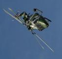
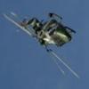
HAS2 in dashing green camo; Zone 19. Exactly what happens when you decide to do an impromptu 'display' when leaving an airshow, when not briefed, authorised or capable! Basic case of not leaving enough air between you and the ground...... -
Lynx Helicopter/ Revell Kit/ 1/32 scale
Lynx7 replied to shark 64's topic in Work in Progress - Aircraft
To highlight Stickys remarks; AH9 Oman Crossmaglen NI Gortin Gap NI Gutersloh/Halle Leeming Armagh NI Incredibly, no serious injuries from any of the above. Lynx do tend to burn rather well though. Oliver, check your messages mate. -
Lynx Helicopter/ Revell Kit/ 1/32 scale
Lynx7 replied to shark 64's topic in Work in Progress - Aircraft
Hooray! Looking forward to this one too. Oliver, I have an unhealthily large collection of photos of crashed Lynx if you need to look at the dynamics of what one looks like (and some of the common damage from a Lynx crash). If you want to really do a Navy Lynx in 'kit form', my pal spanked-in in the Antarctic a few years ago and disassembled his HAS3 to quite a spectacular level.....(his legs were a bit odd for a few years but he's flying again). -
And it is coming! Anyway, more work on the forward decking area. Both AC gennies complete. I made them both out of alloy tubing. The smaller tube coming out of each side is the cooling intake for each. Blocks of styrene will be where the wiring loon will attach. General concept of where everything will go. The three square alloy parts will be the servos, The large white blocks will be the hydraulic reservoirs and the little folded bits is where each hyd manifold will go. Gearbox almost there now. I think I'll chuck this in a mould too.
-
Revell Lynx Mk88 to an RN HAS Mk3 in refurb...
Lynx7 replied to heloman1's topic in Lynx Single Type Group Build
:clap: :clap: :clap: :clap: :clap: :clap: :clap: Fantastic mate! -
As an addition. Having looked at a few pics of Broadswords broken Lynx, it doesnt look like the bulkhead has been penetrated but all the cabling seen is stuff for the radar and the other avionics in the nose? Not sure the rear of the instrument panel is exposed?
-
Thanks mate. To be honest, there isnt much you can see behind the coaming. The Airfix kits coaming isnt quite right (I've mentioned the whole panel sits at too shallow an angle). You can see that the panel doesnt have the extra shrouding found on the real thing (I too haven't covered it either). I've highlighted the area in red. The coaming should pretty much go all the way to the windscreen so any detail behind generally wouldnt be seen. On the HAS2, you would only see the stuff coming out the back of the radar screen and the ancil instruments to its left (compass, airspeed and altimeter) As seen here on a German Mk88A I have quite a few detailed photos of the lower front cockpit bulkhead (in front of pedals) with all the stuff thats attached to that if youre interested?
-
Thanks Mish. More progress. Cast the first engines this evening and am happy its a good mould and cast. There are a couple of bits of detail its not picked up but on the whole, it worked! I've cast a couple more engines after tweaking the inside of the mould a bit (removing little bits of rogue latex) and they have turned out well too. I'll prime them, spray a base bare metal/stainless coat then I can start dressing them with all the plumbing and wiring loom. A most satisfying activity as it transforms them so much. As I eluded to before, I've decided to open up the forward housing too. Detail will include Main Rotor Gearbox, 2x hydraulic packs plus manifolds, reservoirs and plumbing, 2x AC generators on the forward face of the MGB, 3x hyd servos also on the front of the MGB and the control runs running along the top deck. (Photo courtesy of Jens. Thanks mate) Not quite as challenging as you may think because I will use my very detailed references of each sub system and build them up as modules. The first thing I had to do was make up the MGB decking and upper roof area. On the kit, these are recessed but I needed to pad them out a bit. I used plasticard as bolsters underneath to get to the correct level then covered with appropriately sized thin styrene sheet. Engine deck area dry placed too. MGB mounting beams attached and the centre of the Z axis of where the main rotor will sit. This is very important as the top of the gearbox is usually attached to the sliding fairing on the kit but as you will see, I've chopped it off to furnish the top of the gearbox housing. I will need to ensure the gearbox sits at the correct height and the correct position so the blades sit in the correct place too. Start of the gearbox. I cut thin styrene sheet to shape, did a bit or origami to make it look ok then filled it with milliput for strength. This is the bit I chopped off from the sliding fairing and it will make up the top part of the gearbox. I need to blend it in to the top of the MGB. You can see where I've modified the sliding fairing. The prototypes had a subtly different shape to the front (not pointy), no sight glasses for the hydraulics reservoirs and a different opening mechanism. I need to attach the mounting legs to the gearbox and furnish it with oil pump, sight glasses and add the accessories gearbox to the front which will hold the 3 servos, hyd pumps and AC gennies. Overall view of how its getting on. Some of the early prototypes had extra struts fitted at certain parts of the test programme. This was due to excessive vibration at the tail (no change there then!). One of the photos I have of XX153 shows it with them fitted so thought I'd copy that too. I drilled .7mm holes in appropriate places then used .7mm brass rod with metal eyeball fittings I have in the parts box. Ironically, if you look at the non folding tail Lynx, these struts are still present but now under a fairing.

