


Rob de Bie
-
Posts
1,024 -
Joined
-
Last visited
Content Type
Events
Profiles
Forums
Media Demo
Posts posted by Rob de Bie
-
-
10 hours ago, RAGATIGER said:
Hi Rob
you have a very difficul to satisface you know I can only offer some from Hasegawa Typhoon
it look that Hannants have them too
https://www.hannants.co.uk/product/RS72-0450?result-token=F7vL3
Armando, many thanks, I had missed that this little model was issued! I'll go after it 🙂
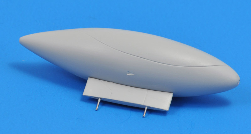
A ventral tank for the Super Etendard? I found one here:
https://www.shapeways.com/product/DKNUTFRNR/021g-600l-ventral-tank-super-etendard-1-72
Maybe you can take another tank or bomb and modify its shape? I did that once, a radome for a UAV.

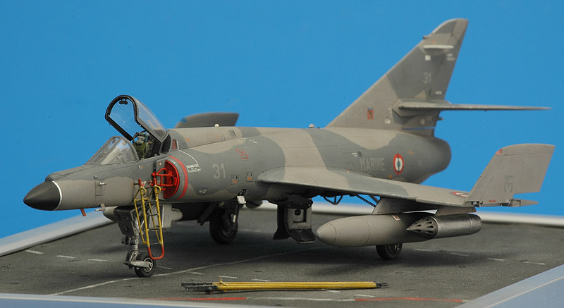
By the way, Super Etendard, I built one 24 years ago, and to be honest it's still my favorite model.
Rob
-
 1
1
-
-
I decided to make heavy paper mockups in 1/72, 1/100 and 1/144 scales (left to right). For scale I used a standard Humbrol tin as the monolith. The 1/72 version was so large that I skipped the surrounding moon surface. It was amazingly large, too large to my taste; it would result in an A1 size diorama. The 1/100 version looked like I had imagined the diorama. It would be A2 size. The 1/144 version was a bit to small for me. It would be A3 size.
Another view of the 1/100 version.
Rob
-
2
-
-
Sabrejet, good to hear you know how it works 🙂 I've done military markings as well as race cars, many many more than shown on the 'Custom decal design service' webpage that I linked to earlier. Like half the field of the 1993 Indy season.
I never got complaints about the decal quality, and I think they look excellent 🙂 However, custom decals are generally dither printed, not silkscreen printed. So if you zoom in, you will see dots instead of solid colours. It can be avoided that by using the old Alps printer, but then your colour palette is limited. I can work with both.
John, thanks for your recommendation! The waiting time for your decals was excessive, since SpotModel (the custom printer that I use mostly) had their printer out of action, followed by an enormous backlog when the new printer went online. That was stressful for me too, since I needed my own decals for an upcoming model show. 😞
As a teaser, here's another recent project:
Rob
-
4
-
-
Thanks for the enthousiasm guys! 🙂 A small warning: custom decals are expensive. It's mostly the time spent on the design. The printing (outsourced in my case) is relatively cheap. So it takes a commitment to have a single custom decal sheet done. Many plans for custom decals fail to take that hurdle, in my experience..
Rob
-
1
-
-
On 4/5/2024 at 4:33 PM, Sabrejet said:
Can anyone recommend a UK-based manufacturer of custom decals? I need someone who can create the graphics as well as printing decals. I have a regular contact in the USA but lately the service has been really poor.
If your question hasn't been answered yet, I've been doing decal design for more than twenty years now. I'm not in the UK, but on the other side of the North Sea.
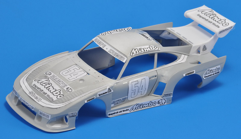
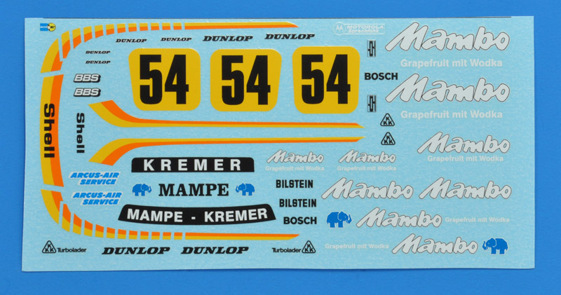
Time permitting, I do custom decal design work for other modellers, for a fee. On average, I do one or two assignments per year. Here's my most recent car project, a full decal set for a Porsche 935K3.
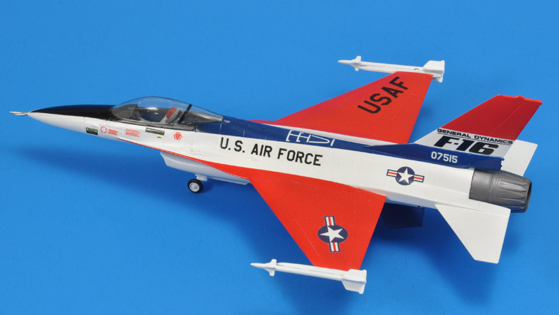
And here's an example of the decals applied to a model, the old Revell 1/72 F-16:
More information can be found here: https://robdebie.home.xs4all.nl/models/customdecals.htm
Rob
-
3
-
-
In the mean time I had a 1/72 paper version of the walls and ramps printed. And it's huge 🙂 I will also do 1/100 and 1/144 versions. Also I need to check the 'printability' of the 1/32 astronauts at those scales, and figure out whether I can build working spotlight with SMD LEDs.
Rob
-
1
-
-
On 4/1/2024 at 1:18 AM, internationalrescue said:
Hello Rob,
Definitely a great subject to build! The figures look really nice and accurate. In response to your questions:
Question 1 - I think scale is all builder preference. I typically back into the number based on what I have to build with. If your figures are what you'll be using and they are only available in 1/72 that scale would make sense. I also like to consider the overall footprint of the diorama. The scene you referenced is long and deep if you build the walls to scale. It's a little like a shoe box and probably the perspective will be from one short side of the box to the other with a gradual down slope. I think a larger scale would work well. However if you are thinking more of a top-down perspective a smaller scale might work.
Question 2 - I have not tackled this project so take my comments with a grain of salt! 🙂
Question 3 - I own The Making of Stanley Kubrick's 2001: A Space Odyssey book by Taschen which has some great screen shots but no drawings. Keep in mind this book is vertical 15" x 7" and one of the most frustrating books I've ever owned; very challenging to open but the fold out images are nice. There is another book on my wishlist titled 2001: The Lost Science Volume and I've heard it's a great reference but it's expensive and challenging to find.
I hope that helps and if you decide to proceed look forward to following your build!
Cheers,
Dale
Dale, thanks for your extensive reply! The STL-files can be reduced to any scale desired, until you reach the limits of what's printable. My current calculations show a 42 x 17.5 x 7.5 m pit, or 138 x 57’ x 25’ in imperial units. Very roughly shoebox size in 1/100 scale. Mock-upping is definitely called for, for the reasons you mention.
Thanks too for checking your 2001 books. I will work from the screen shots, with their limitations. I found a site with 100s of BlueRay screengrabs, pretty amazing: https://movie-screencaps.com/2001-space-odyssey-1968/
Maybe I'll get a first 1/72 test print of a single pit wall panel, ~18 hours from now, at a club meeting 🙂
Rob
-
2
-
-
On 3/31/2024 at 6:30 PM, Hamiltonian said:
No useful illustrations of the TMA1 excavation in either Taschen's "Making of ..." or the "2001 File", beyond some concept art that doesn't match the "real" thing. That set seems to have little in the way of surviving documentation, unfortunately.
Hamiltonian, thanks for checking your references! I think I saw at least a few in this massive 2001 photo collection: https://www.flickr.com/photos/2001archive/. But as you say, they don't match the final movie set, so they are of limited value for my diorama plans.
Rob
-
1
-
-
On 3/30/2024 at 7:44 AM, Yoshizakura said:
Sorry I can’t help, but yes, I’ve often thought of this myself, but only as a thought.
I believe architecture models are 1/100? Which is rare outside architecture and gunpla. But it might work.Yoshizakura, thanks for the suggestion. I think I will mock-up two scales, to see the overall sizes.
Rob
-
1
-
-
James and bentwaters81tfw, thanks for the confirmation!
Corsairfoxfouruncle, if you want to start casting, I happen to have a tutorial on my website: https://robdebie.home.xs4all.nl/models/casting.htm Here's the result of the most recent casting session.
Rob
-
1
-
-
Matt, thanks! Indeed I found the parts in the instruction sheet on Scalemates: https://www.scalemates.com/products/img/4/2/3/111423-41-instructions.pdf
If anyone knows another kit with these racks, please let me know!
Rob
-
Are there any B-17 kits that have the external bomb racks, in any scale? Here's a webpage on the subject:
http://axis-and-allies-paintworks.com/e107_plugins/forum/forum_viewtopic.php?10679
I looked around in the instruction sheets of various kit at Scalemates, but saw none. Thank in advance for any information!
Rob
-
1
-
-
I've always loved the moon excavation chapter in '2001', and thought a few times of building a diorama of it. It would be a large undertaking with nearly everything scratch-built, so it never progressed past thinking about it.
That was, until a few days ago, when I found a great set of figures for 3D printing:
https://www.cgtrader.com/3d-print-models/miniatures/figurines/vintage-lunar-astronaut-setThat made me reconsider building that diorama. Still a ton of work, but with some 3D printing and resin casting, it might be do-able. Three questions:
1st question: what scale would be most logical in the SF modelling world? As a mostly aircraft builder my first idea is 1/72, but maybe 1/96 is more standard? I'm thinking of Revell space models in that scale.2nd question: did anyone here attempt the same diorama idea? I'm very interested to learn from it.
3rd question: were any drawings of the moon excavation published in the 2001 reference books (of which I have none)?
Rob
-
3 minutes ago, Vesa Jussila said:
I think we all are out of medication. Similar plans here too. Rob you need to remember these were pipes and there was gas inside. So pipes in scale of course.
You probably mean they were pressurised with air, and a gauge told the crew whether a crack had developed?
I have been thinking about a stand-alone chassis made from soldered Albion micro-tubing, that would allow the use of different sizes of tubing. I even drew some jigs that would be required. I know what sizes tubing were used, but not where, that stopped the plan..
Rob
-
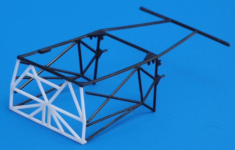
21 hours ago, Bozothenutter said:
Somebody with CAD skills should do a replacement unit, showing the whole front frame. (maybe add in the details under the front bonnet too?)
maybe some vacform bodywork.....🤔, bonded to a brass soldered frame.....
Time for my meds again I guess.......🫣
I forgot my medication too, and started work on the rear half of the frame. Black is Heller, white is mine.
Rob-
2
-
-
On 8/21/2012 at 5:21 PM, Mark said:
Thanks all for taking the time to reply!
I've just had the Union Porsche 917K come through the letter box and the parts look great for the era that the kit is supposedly from; it certainly shows up a lot of modern kits! I have never heard of this being 1/28th or anything odd, and the length of the original car is quoted on 5 different websites as being 4120mm. Divide 4120 by 24 and you get 171mm which is exactly the length of the kit. The bodyshell compares very well to the Tamiya 956 and 962 kits, so I'm going to stick my neck out and say yes, it's definitely 1/24th!
So far my idea is to take the Fujimi kit's best parts and add them to the more accurate Union chassis and body and maybe try and add the Hiro engine.
Nuts? me? Definitely!!
Your 11 year old post suggests that you don't know that the Union kit IS the Heller kit. It was also issued by Wave and Testors. I too like this kit a lot!
I've made a Porsche 917 kit list (1/8 to 1/24 scale) with 166 different issues: https://robdebie.home.xs4all.nl/models/917kits.htm
Rob
-
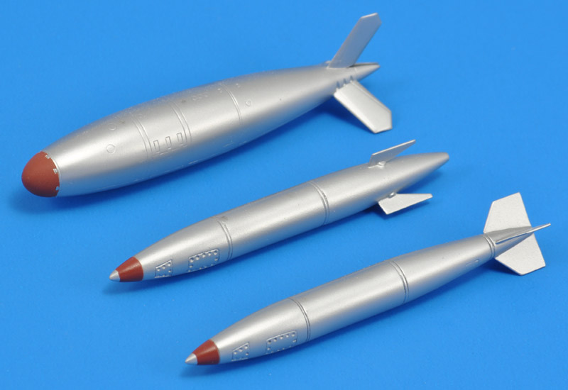
13 minutes ago, RAGATIGER said:
1000 Thanks Rob
I just checking and find that
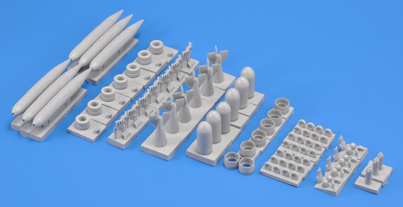
Yes, those are the bombs I built for my F-84F project. The front one, the B28EX, is the corect one. In the middle is the B28RE, but it's REtarded, and that doesn't work in LABS bombing, so it's out for the F-84F. In the back is the Mk7, as used by USAF F-84Fs. Note the fin orientation. I think the center part of the bomb should be more cilindrical by the way.
I thought of something more regarding the Mk7 / B28 choice for the NATO air forces. I have to investigate this further, but I think the B28 had a Permissive Action Link feature, that the Mk7 does not have. If I was the US government, I would really like have this extra safety feature against inadvertent use, for allies that might have their own agendas, and personel that's not under US control.
Rob
-
4 hours ago, RAGATIGER said:
Well recently there been an influx of nuclear bombs on plastic models in the Wonderful 1/72 scale some of you called the Gentleman Scale (sorry I didn't fully understand that joke) so Modelvit AMD Mirage IIE. Modelsvit Su-7 Fitter, now Special Hobby Republic F-84F, Italeri Aircraft Weapons and Valom F-101A Voodoo (the one I didn't got in time) all included Nuclear bombs so in my madly Cold War kid weird brain I plan to do a MiG-21 Bis, AMD Mirage IIE, F-104G not sure if Belgium or Dutch with a B61
Armando, glad to be of help with the nuclear armed Thunderstreak. For much more on Streak stores, see my RNLAF Streak stores project.
Regarding the Dutch or Belgian F-104G with a B61: from 1977 on, USAF replaced the older weapons (B43 and B57) in the air forces of Belgium, Italy, Germany and the Netherlands. with the B61 weapon.
Rob
-
On 3/22/2024 at 3:34 AM, RAGATIGER said:
Then of course the thing of the Mk 7 Nuclear Shape so Who on the NATO F-84F used it
Armando, with some doubts I would say none. It's my presumption that the B28 was the weapon used by NATO F-84Fs.
I investigated RNLAF extensively, and I'm sure that it used the B28. The RNLAF Streaks never had the special pylon required for the Mk7 on the left inboard position, always the standard pylon. That pylon could be configured for two purposes: fuel tank / conventional weapon *or* nuclear weapon. To be always ready, the Volkel Streaks always flew with latter, Eindhoven with the former. Volkel therefore flew with a right inboard tank only, an asymmetrical configuration.
So far I've seen German, Italian and Greek Streaks in that same asymmetrical configuration, with the standard pylon. But seemingly not as a standard configuration like Volkel. But I've never seen the Mk7 pylon on any of them. That lead me to think all other European also used the B28. But the proof is not as strong as for RNLAF, that I investigated far deeper.
The only NATO country that ever showed the Mk7 pylon is BAF, when their Kleine Brogel Streaks were put in storage at Koksijde. But that *could* be to cause confusion, why else show that nuclear capability with stored aircraft?
Rob -
54 minutes ago, Vesa Jussila said:
@Rob de Bie or maybe taking greenhouse from normal 911 kit? If I remember correctly rules demanded to keep original doors and roofline and window shapes. Maybe we need to start separate topic to cover correcting various 935's.
Ah yes, of course, a street 911 could be used too.
I have to add another comment: I based my 'door width' theory on the assumption that the Tamiya 935-76 is 100% correct. Which is not proven, at all. But you can see the 'thin' doors in any Porsche 930 photo.
Rob
-
The following is not meant as a comment on Davi's model, but mostly as a review-type comment. I studied my own Italeri 935-77 a bit more, concentrating on the shape. I don't have a fixed method for that, so it's a bit hit and miss. But I found one clear problem. Earlier, I had noticed that the width of the model is 4 mm over the published overall width of 1998 mm, but I could not identify the cause.
I think I found it now: the doors are too wide by that same figure. What I mean is that the 911 from that era had quite 'thin', delicate doors, as depicted by the Tamiya model. Nitto made the doors far thicker below the windows, they almost look bulky, and that extra width is continued in the rear fenders. It's a fairly subtle shape problem, one I hadn't encountered before. That's why I'm posting it here.
I've been wondering whether it can be corrected, but that's really difficult I think. A kitbash of the Tamiya 935-76 greenhouse with the Italeri 935-77 is a solution, but close to madness..
Rob
-
Thanks for the comments! I just updated the page with photo of the equipment.
Rob
-
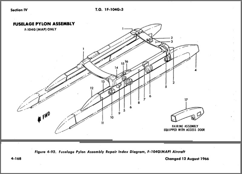
59 minutes ago, Giorgio N said:
Sorry Rob, I misunderstood your post.
The BL-22 pylons of the S attached directly to the fuselage undersides and are independent of the central pylon.
Here's a drawing of the pylon from the parts catalogue:
I'm looking at the section of the catalogue describing the fuselage, there should be the attachment points shown. However the fuselage section is several pages long and finding the right details is not a quick job...
Thanks Giorgio for clearing that up! I learned something new about the 104.
Rob
-
7 hours ago, Giorgio N said:
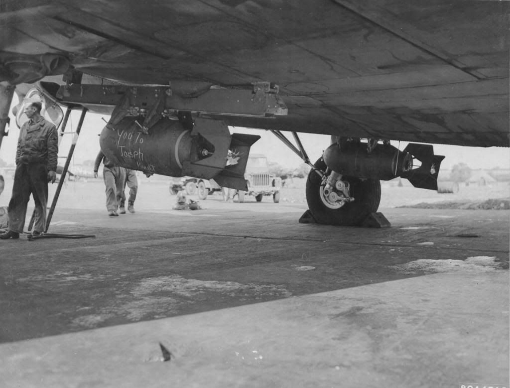
The pylons under the intakes visible in the picture were only on the F-104S. Known as BL-22 (all F-104 pylons are known as BL-xx, where the latter is the distance from the fuselage centre), they were indeed rated for the use of bombs but this never happened during service: the bombs in that position caused a lot of drag and there were concerns about the ingestion of foreign objects in the intake when dropping the bombs. There are some pictures showing bombs under these pylons but they are all of either test flights (as above) or aircraft on static display on the ground.
The same pylons were initially used to carry Sidewinders but the missiles in this position were quite close to the ground and the sensor got covered in dirt during the take-off run so the use was soon discontinued. All aircraft retained the capability of using these pylons until with the ASA-M upgrade all relevant wiring was removed
Thanks Giorgio. But I phrased my question unclear. Here's the 'Fuselage Pylon Assembly' of the G-model, from the Structural Repair manual. The assembly attached in the slot for the centerline pylon, i.e. in the middle, with a cover plate over the centerline pylon slot. That's not clearly shown in the drawing BTW. The flight manual indicates that only AIM-9s could be carried on the pylons.
My real question was whether the 'BL22' pylons of the S-model are also connected by cross braces and attached on the centerline, or did they connect directly to the fuselage?
Here are a few hi-res photos of the G-model installation on RNLAF 104s:
Rob


CMK 1/72 Taurus KEPD 350 cruise missile
in Wanted
Posted
I just ordered the Reskit 1/72 Taurus, straight from Reskit, along with some other sets. Thanks again for the tip!
Rob