

Alex Gordon
-
Posts
2,049 -
Joined
-
Last visited
Content Type
Events
Profiles
Forums
Media Demo
Posts posted by Alex Gordon
-
-
Hello again Chums,uncertainty this time.
Toryu,thanks old bean.I don't have any Gunze paint at all but thanks for the pointer.
Paul,thanks old fruit.Looking at the photo there doesn't seem to be a difference in the smoothness and shape between it and the kit but it's one of those things that might be handy to be aware of.
Col,cheers old chum.You're going to really enjoy this next bit.
It turns out that the machine I'm going for has been dicussed before https://www.britmodeller.com/forums/index.php?/topic/235044015-tiger-moth-k-4288-d-colour-questions/
Having pulled out the suspect creation and used it as a pattern to knock up a mirrored replacement which,to my eye,came out a little more refined than the first one

I had another look at my modified photo.Something didn't look quite right,there was just something about the instruments and orientation of the compass.
I had a bit of a twiddle in Paint and came up with this image.
Anyway I've one of each now and as this will be a two seater they will both be going in,one each side.I'll also have to make the padding to go on the rims above the instrument panels so that the incumbents don't have an oooh nasty if they have a whoops a daisy.
Yet another photo I didn't note the origin of.
This one's got levers on both sides of the rear cockpit,now I'm really confused.
More soon Chums,thanks for looking in.
-
 2
2
-
-
I would say so,there is what seems to be an edge visible where a screen would end.It looks like there is a cut in next to the hinged side framing but the open end seems to head the other way.
-
I would think a length of thin wire and a drop of Klear would sort it out.
-
1
-
-
G'day again Chums,a spot of progress.
Col,thanks old chum.You're going to laugh your bits off at the end of this post.
The fuselage halves have been put together
with the anticipated joints showing up.
The engine has had a slap of paint.The vertical tubes in the cooling duct didn't push all the way across to the wrong side as I thought they might.
I thought I'd put the cowling together.
The sequence on the map was followed but the aft end of the upper portion was only temporarily fixed so that the assembled lump could be removed.
As it turns out the assembly can be done away from the fuselage with a little dexterity and perhaps a bit of tape to hold the components together before glueing.
The spinner has come up rather well.
I've been looking at the paint job.The map recommends Humbrol 19 Gloss Bright Red (didn't it used to be Post Office Red many moons ago?) but it doesn't match the decals.Nor did any of my quick mixes adding a drop of black to darken it and none of the other reds in the paint store come close.
The kit supplied decals are good for the machine currently flying but are far enough different to the original scheme to cause me to think again.
This has led me to have a change of direction.If I've got to mess about with all the markings I might as well take another route.Found here https://www.pinterest.com/pin/302233824965583108/
A run of the mill training machine the gen for which is;3284 Toc as K4288 at 2 ASU Cardington 9.5.35. To 18 ERFTS Fairoaks 16.9.37; coded "3". Unit re-designated 18 EFTS 15.10.39. To 10
MU Hullavington 30.7.45. Soc as scrap 25.5.50.All of the above digging won't be wasted,it is all in one place so any that tread this path can have an easier trip.It also means that I'm building something more representative of the many and not something specialist and niche.
Anyway,if you remember the bits I added to the cockpit last time it turns out that I've fallen foul of the Dreaded Flipped Photo Syndrome.Deep joy.
You may now stop giggling,more soon Chums,thanks for looking in.
-
1
-
 1
1
-
-
This short bit of video might be of use.
-
G'day again Chums,there has been paint.
Cliff,thanks old chum.
Troy,thanks for the mention in Nicks' thread.That's quite something to live up to,I'll do what I can.
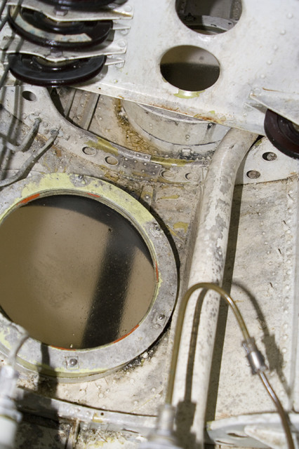
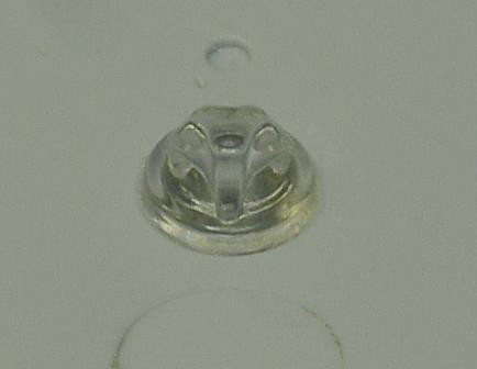
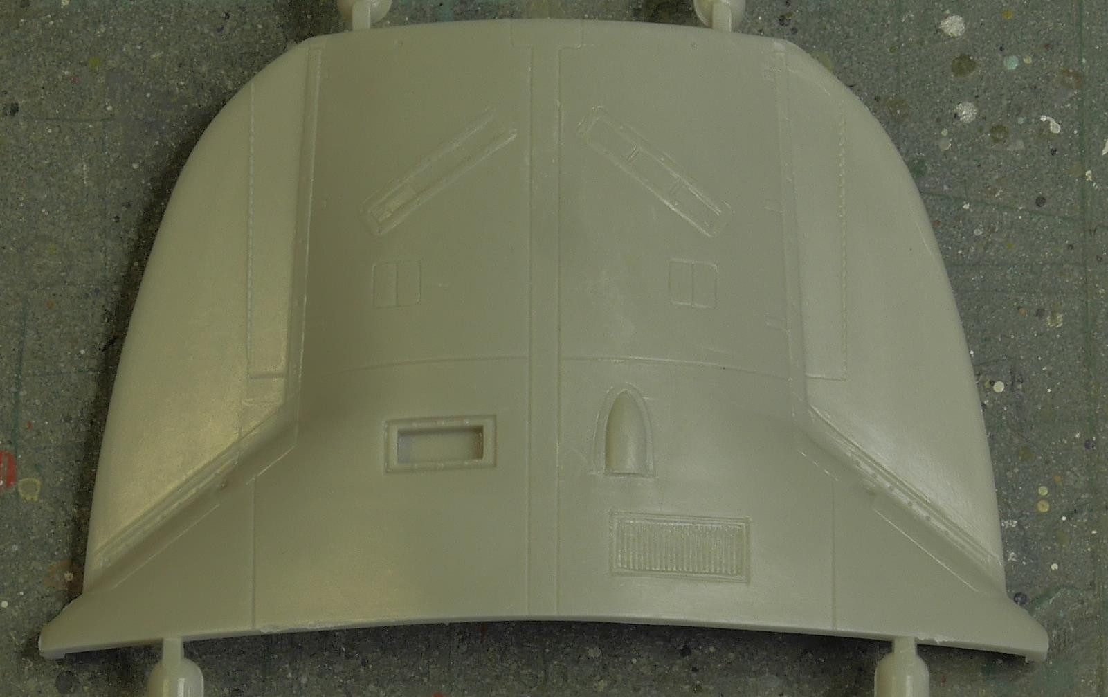
I've been digging through some of the photos that I've acquired along the line and found some that I'd forgotten about but may be of interest.This one is of the inside of the vertical camera ports I presume on a PR XIX but I would think that it is very similar on the XVIII.
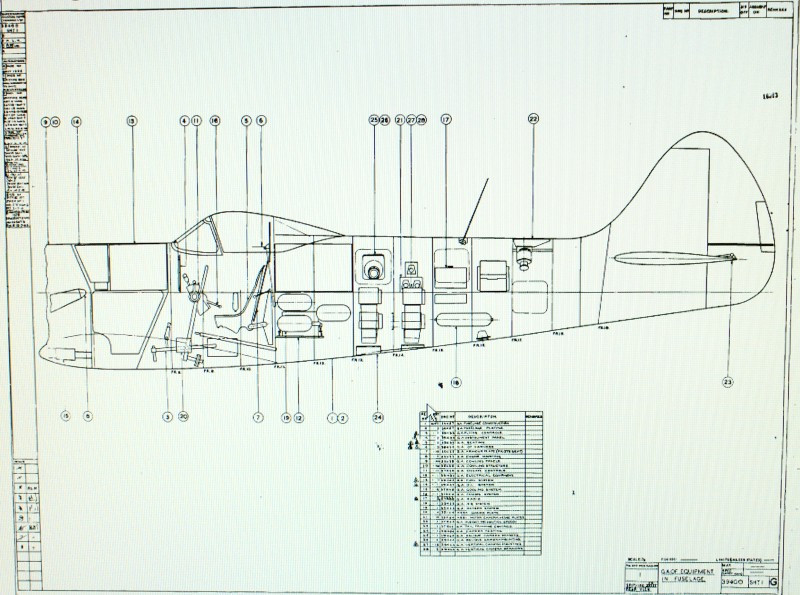
I've no idea where this one was found but it is a general arrangement drawing for the XVIII
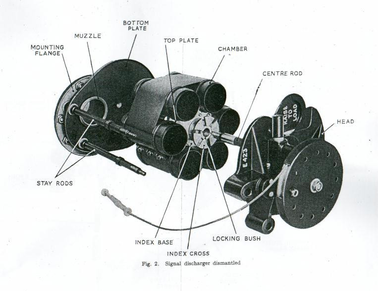
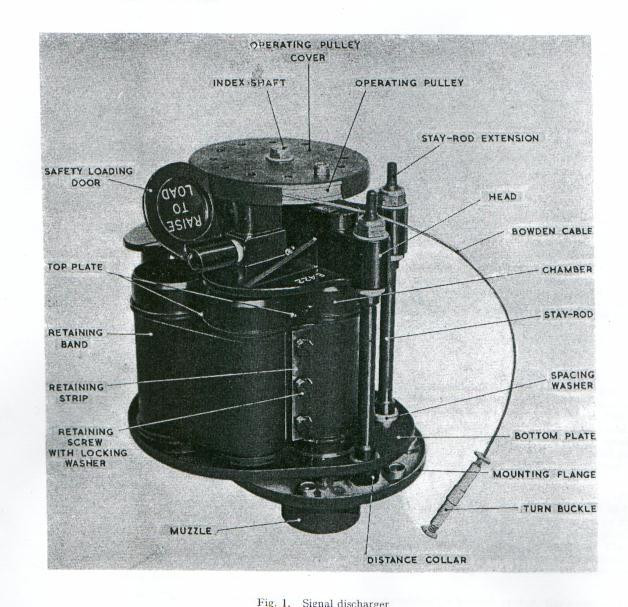
which,among other things,shows the location of the Signal Discharger in the aft fuselage just forward of the fin.
I don't have any gen on the exit method from the fuselage.
There has been green paint.The pilots notes contains three not very distinct photos of the cockpit which,in the absence of anything else,I'm using as a guide to adding in a few odd bits.The port side is going to have the bomb selector control panel,the mount for the gun camera film indicator and the radio pushbutton controller.
The starboard side will have the identification light switch box,the recognition light selector switch and the gunsight dimmer unit for a start.
There will be a few more bits too,all made from runner,plastic card and copper wire,to the limit of my boredom threshold and the will to live.
More soon Chums,thanks for looking in.
-
6
-
-
G'day old fruit,in answer to your question in the GB chat thread I've found this image here https://www.flickr.com/photos/27862259@N02/6102932459
which shows both IFR probes so for my money leave them both on.
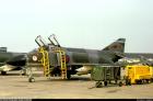
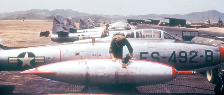
This next photo was found here https://www.nationalmuseum.af.mil/Visit/Museum-Exhibits/Fact-Sheets/Display/Article/196087/interdiction-tightening-the-noose/.
This link might be worth a moment of your time too https://www.flickr.com/photos/27862259@N02/6102932459
The thing I would like to know is when I was putting my first one together why didn't any of these photos show up in the seemingly decades of Googling I engaged with.
She's looking superb so far old lad,glad the nose decal went on with no problems.
-
 1
1
-
-
1 hour ago, Corsairfoxfouruncle said:
Id love to get one of those but they go for $60 dollars plus here. Way out of my meager budget allowance.
Crumbs! I don't think mine cost me above three quid!
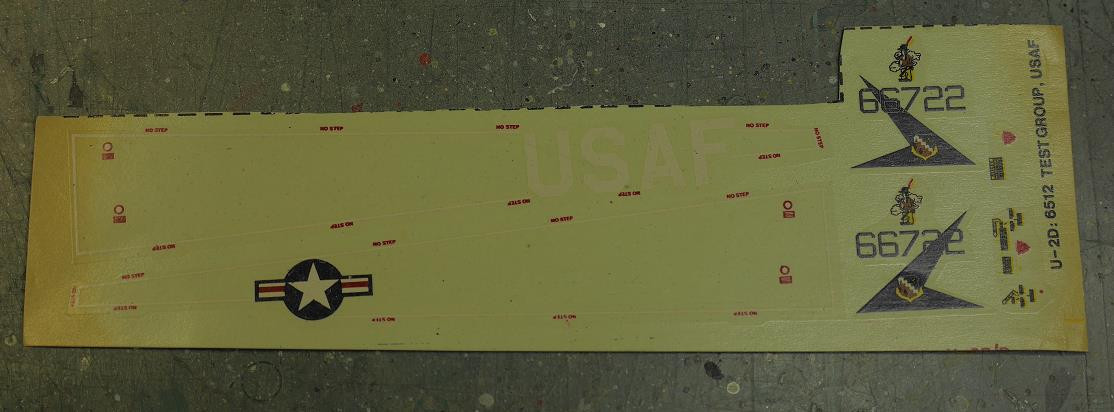
I've still got these if you need them Col
and my instructions were printed in blue as well.
-
1
-
-
I built that one thirty years ago,it might be rose tinted memories but I seem to remember it was a pleasant build and came up rather well.Enjoy old chum
 .
.
-
1
-
-
Hello again Chums,some more done.
Toryu,Dennis,thanks chaps.The IPs are all down to Cartograf,all I've done is slap a bit of paint on and place the decals.
When you know what to look for things turn up. https://benitz.com/Watt/WattPercyM1906_Photos.html was found while looking for Charles E. Brown images which contains these two photos
Anyway I thought the cockpit still looked a bit bare after a coat of green paint.
Yet another photo,the origin of which I didn't make a note of when I found it,gave me a bit of an idea of what to add.
A few bits of plastic card and runner later
followed by a drop of paint gave me this.
The instrument panels went in with no problems.
The fuselage halves have been glued together and taped up tightly to make sure the gaps were closed up properly.The fit is good but needs a little assistance.The clamp at the aft end is to stop the slight up/down displacement that it seemed to want to do.
Finding photos of how the propellor looked took a bit of doing.I eventually ended up here https://www.baesystems.com/en/heritage/de-havilland-dh60giii---moth-major where I found this photo
which gave me a bit of a clue.Then the Percy Watt page above turned up a decent size photo which was just what was required.
Thanks for looking in Chums,more soon.
-
5
-
-
Hello again Chums,a bit more done.
Linescriber,thanks for dropping by old fruit.
The exhausts have been cleaned up,hollowed out and painted.
The fuselage identification lamp has been glued in and will have a coat of the shiniest silver I can muster.
The glassware for the downward facing camera ports has been made from thick clear sprue and the usual succession of ever finer grades of Micromesh.A drop of Klear will finish them off once in place.
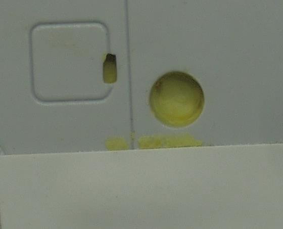
The underwing lamp reflectors have been made
by trapping a blob of Milliput between the wing halves and then pushing the rounded end of a length of runner through the hole.
Most of the interior bits are now mounted on sticks ready for paint so construction can start in the near future.Thanks all for looking in,more soon.
-
4
-
-
G'day again Chums,a little more to show.
Marvinneko,Robert,thanks for popping by.The biggest snag I have with drilling is the magnifier lamp that I can't do tiny stuff without.Its fixed focus lens invariably positions it just that fraction too close to whatever I'm working on which means that when I try to wield a paintbrush or use a pin vice I end up knocking into it with the usual consequences.That and the fact that PCB drills tend to have an aggressive bite which draws them through the work until they bottom out before rounding the hole off and can be difficult to withdraw without giving that slight sideways twitch which,on a 0.3mm bit,is usually fatal.
Jean,glad you got the PM.It was only after I pressed send that it occurred to me that Amazon might not be an entity in your neck of the woods.
To assuage curiosity
https://www.amazon.co.uk/sourcing-map-Tungsten-Carbide-Engraving/dp/B07ZVRV33N
https://www.amazon.co.uk/WayinTop-Carbide-0-3mm-1-2mm-Circuit-Engraving/dp/B07S82M2GM
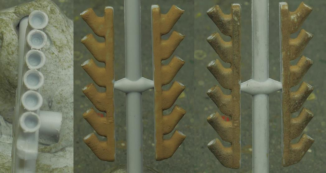
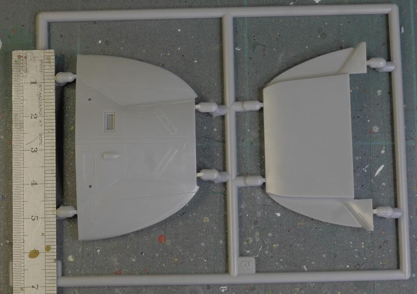
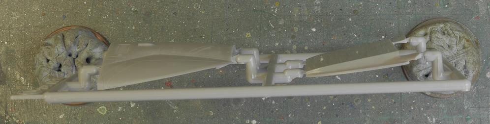
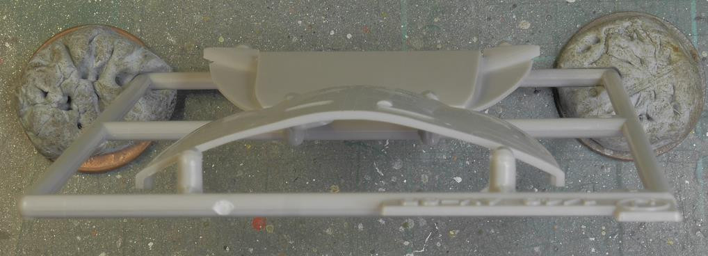
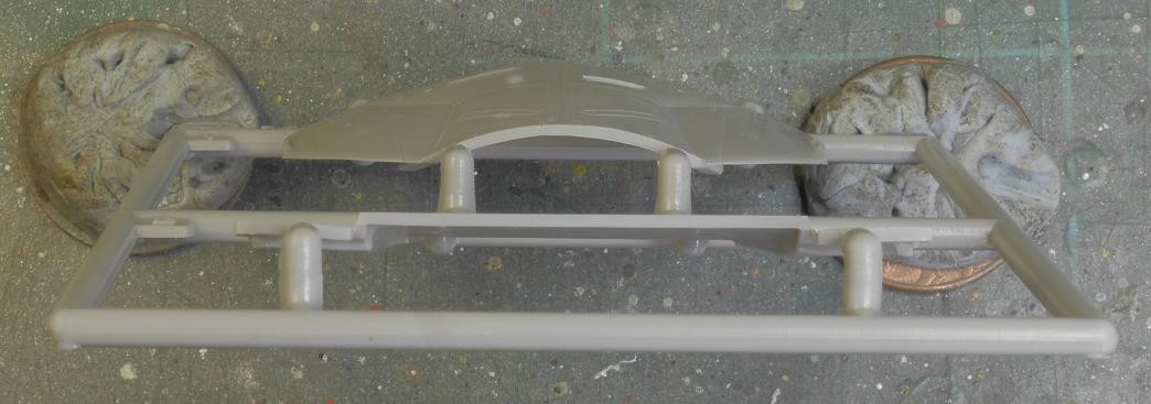
I thought I'd have a look at the propellor.The spinner is a tiny little thing that looks like it might be fun to position.
There is a choice of three propellors,the one in the middle is appropriate for a 1930's aircraft.
The gates look formidable but aren't difficult to clean up if cut through carefully.
In the 1930's wooden propellors on military aircraft weren't painted black https://www.britmodeller.com/forums/index.php?/topic/235125186-1930s-tiger-moth-propellers-painted-black-or-not/ .I gave the centre of mine a coat of Humbrol 119 Light Earth.Once dry I started the process of masking and painting the darker laminations with 29 Dark Earth.
The instrument panels have been painted and the decals applied.
More soon Chums,thanks for looking in.
-
7
-
-
Hello again Chums,some twiddly bits.
Jean,thank you very much old chum.Those photos didn't show up on any search I did and they are exactly what I was hoping to find.
The photos linked to above originate from the RAF Museum collection and were taken by Charles E Brown.They are trying to sell copies of these so I'd better put a link here.https://www.rafmuseumphotos.com/royal-air-force/display-teams/tiger-moth-i-aircraft-central-flying-school-1768743.html
I can't make out the front windscreen framing on any of the aircraft so I will agree with Jean that they were not fitted.
The exhaust pipe has been painted with Humbrol 119 Light Earth and then rubbed over with pencil lead dust.
The first of the rigging anchor plates have been superglued on.
Some of these are tricky to make.
I'm starting to panic about the number of 0.3mm drill bits I'm going through on this caper.
Thanks all for looking in Chums,more soon.
-
4
-
-
G'day again Chums,a little more done.
Jean,thanks for popping in old fruit.Your build does look good,it's a bit odd how the interest can wane when something is going well.I don't doubt you but is it possible that the aircraft were supplied with a cover for the front cockpit when not in use? Photo found here https://www.expressandstar.com/news/Features/2021/10/29/moth-mystery-to-test-aviation-experts/
Photo found here https://www.bbc.co.uk/cambridgeshire/content/image_galleries/tiger_moths_gallery.shtml?13
I've enough walkaround photos to be going on with but if you've any images of K 2585 from its life between 1931 and 1938 I'd like to have a look because I haven't found one yet.I'm quite happy if you pass me a link to any,it'll save all that fussing about uploading and so on.
I must admit this kit does have a feel about it that is good,there's a lot that has been well thought out and makes life easy for cleanup and painting.
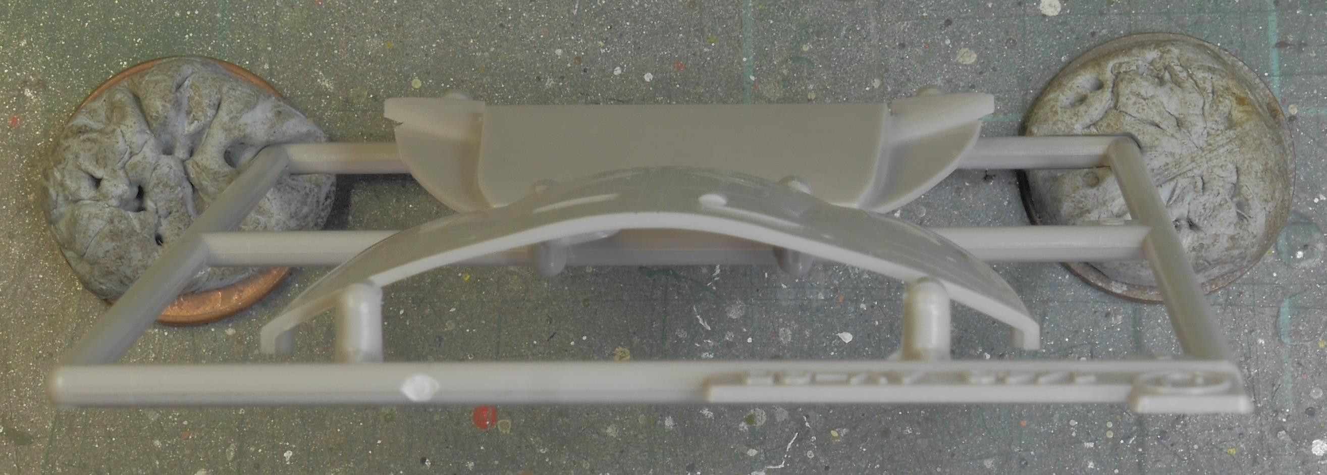
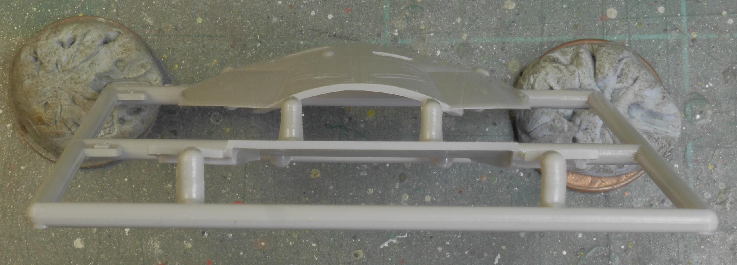
The struts will have a spot of Milliput around where they have been mounted.
The pushrod tubes and cooling duct will be painted before bits are glued together.The map shows them being pushed into the far port side of the duct.
I haven't tried the fit yet but it should look like this,yet another photo I didn't make a note of where I found it,apologies to the owner.
The cylinders look well enough for how visible they are going to be.
I saw the exhaust tube and thought it was going to be a right game,there's this huge great big gate right on the most visible bit which,once I'd put a thin saw through it,
turned out to be the tiniest attachment point I've seen in a while and didn't take much cleaning up at all.
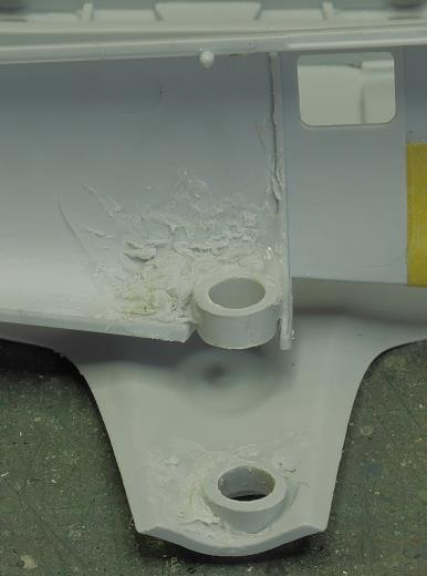
I was going to glue the oil tank on until I remembered that I've got to paint behind it first.I might have to add the filler tube to it too,much easier when you can get at it and nothing's in the way.
More soon Chums,thanks for looking in.
-
7
-
-
G'day again Chums,a little more to show.
Troy,thanks old chum.I bought a set of three hinge drills from Screwfix (it's not a dating site) for not a lot of pennies a few years ago and they've got me out of trouble more times than I'd care to count.
The exhausts are going to need a bit of attention,from the few photos I've seen the tubular ones seem to be the thing.
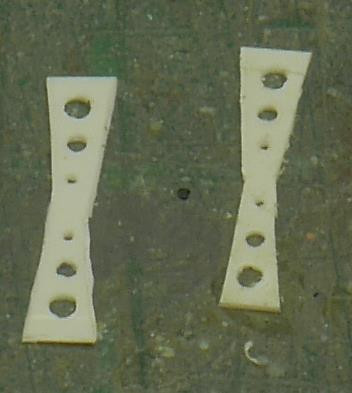
A pair of torque links have been made from thin plastic card
and fitted into slots cut into the mainlegs.Once again a little refinement will finish them off.
The outer wing recognition lamps have been drilled out to the same diameter as the central fuselage one.There's something niggling in the back of my mind that the fuselage lamp should be moved aft but that might just have been the VIII and I haven't found any photos to support that one.Anyway I think the wing modifications are all done.
A couple of tubes have been turned in the cordless drill for the downward pointing camera ports and fixed in place with some sprue goop to give them half a chance of not falling off.
The carb air intake should look like this,from the BM walkaround department
so I've filled the visible bits of the joints and made the shutter from a couple of bits of plastic card.
More soon Chums,thanks for looking in.
-
4
-
-
She's looking rather spiffing so far old fruit
 .The decal around the nose doesn't fit at all which is a bit frustrating because the rest of them are about spot on.
-
1
-
-
No worries old fruit.I had another thought,if you've the smaller LERX to hand it's not a huge leap to build them up from there
Click on these links for the big images
https://bg-so-1.zippyimage.com/2024/04/01/8dd96d026dc406dede7328feb853e15a.jpg
https://bg-so-1.zippyimage.com/2024/04/01/e1a6105dfcd8f15c03b0c6cc3e78e511.jpg
-
As Troy said open in new tab,right click,copy image link,paste into thread.
If you are doing multiple links they can be pasted into Notepad first so that you've got them all in sequence and together.They can be copied and pasted en masse so that you're not shuttling from one tab to another and back again which I find confusing at times.The link to your image above is https://images2.imgbox.com/6a/2c/N8txgNIf_o.jpg .
-
1
-
-
Cocktail sticks,Blu-Tack,Superglue,masking tape and a coin do most of it at this end.
-
Hello again Chums,a little progress.
Cliff,thanks old fruit.
Col,Dennis cheers chaps.I'm going for the boxart scheme on this one but I'll have to take it on trust because I haven't found any photos of it from way back when.I found the gen for this one here https://air-britain.com/pdfs/production-lists/DH82.pdf which reads;
1757 (Deld without engine) Toc as K2585 at Home Aircraft Depot, Henlow 19.12.31. To DH 6.4.32 for conversion to inverted flying. To CFS Upavon 13.5.32. Returned to DH 11.8.32 and converted to standard. To 2 ASU, Cardington 30.9.32 for storage. To DH 10.4.33 for conversion to inverted flying. To CFS Upavon 9.5.33. To HAD Henlow 24.7.33 for conversion to standard; to store 10.11.33. Removed from store 29.10.34 and used locally for Cardington ferry pilots. To 24 Squadron, Hendon 22.1.35. To DH 11.5.35 [repairs?]. Returned to 24 Squadron 21.5.35. Reported on charge RAF Church Fenton 5.37; unconfirmed. Converted to instructional airframe 1157M at 5 School of Technical Training, Locking 28.10.38. To 6 MU Brize Norton 9.11.38. At RAF Weeton [31.12.42].
which basically means it wouldn't have had the anti spin strakes added to the aft fuselage having been relegated to maintenance training well before the modification at the end of 1941 https://www.britmodeller.com/forums/index.php?/topic/234986688-148-aeroclub-dh82a-tiger-moth/&do=findComment&comment=2067541.
I've started to alter the pitot tube mounting by thinning it and chopping off the unwanted bit.
The mounting plates for the rigging have been started.A series of 0.3mm holes have been drilled into the edge of a PE brass fret which has been suitably scribed most of the way through to make a strip.
This strip was then bent back and forth until it broke away because cutting it off with scissors gave me a bent curly lump which wasn't going to be easily useable,top right of this piccie.
Apologies for lousy photography,the airspeed indicator is represented by a featureless triangle on the port forward strut.
It should look like this,picture found on Pprune
I made something that looks a bit less featureless from some more of the brass fret soldered together and a bit of wire.I haven't worked out how I'm going to fit the vane with the spring yet.
The struts have been glued to the upper wing so that the fillery can be done while I can still get at it.
Thanks all for looking in,more soon.
-
7
-
-
Hello again Chums,some chopping and hammering and a bit of digging this time.
Troy,cheers old chum.
I found a copy of the Pilots Notes here https://ww2aircraft.net/forum/threads/spitfire-manuals.9050/post-1620131 which states on page 23 (page 13 of the PDF) "Desert equipment can be carried in stowages reached through access doors in the upper surface of each wing." It also mentions a signal discharger in the rear fuselage.
This image,originally posted by Edgar,will look very familiar to some folks,apolgies Troy I've pinched your URL for this one.
It tells us what was carried and in which compartment.I've seen nothing so far about how to get into them so I went looking for any more gen on maintenance and wound up on the National Archive site https://discovery.nationalarchives.gov.uk/results/r?_q=AP+1565Y&_sd=1945&_ed=1955&_hb=tna which has all sorts of goodies but none available to download.
Anyway I'm intending to do TZ 233 using Xtradecal X48-127.
As mentioned earlier the gen is TZ233 FRXVIII ALD G67 33MU 4-2-46 MED(ME) 6-7-48 109MU 31-12-48 208Sq 'RG-T' 10-2-49 SOC 10-12-51.
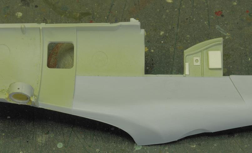
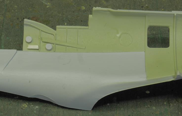
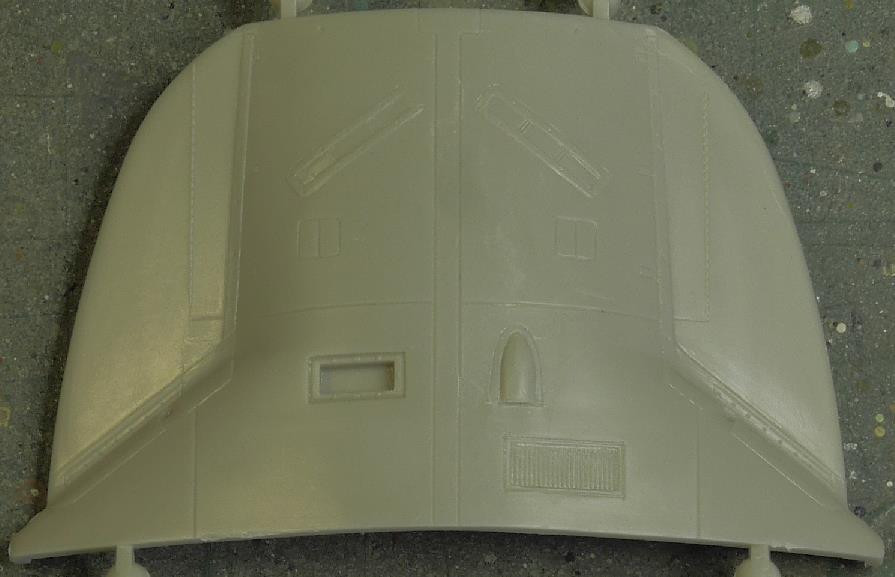
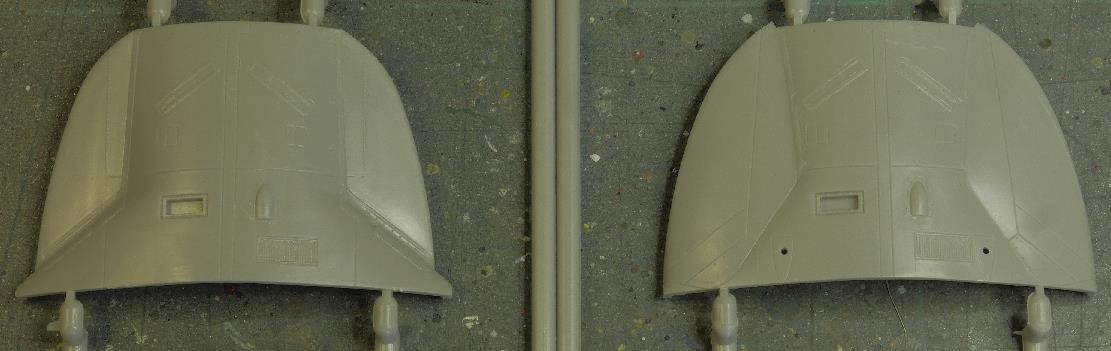
There were two sorts of Mk XVIII,the F and the FR.The FR had provision for a pair of vertically mounted cameras as well as the horizontally mounted one looking out of one side or the other.Supermarine were noted for not re-inventing the wheel so I think the setup would probably have been the same as in the PR XIX.Based on that premise I've been drilling holes.
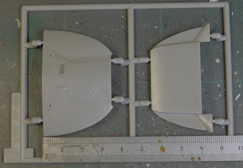
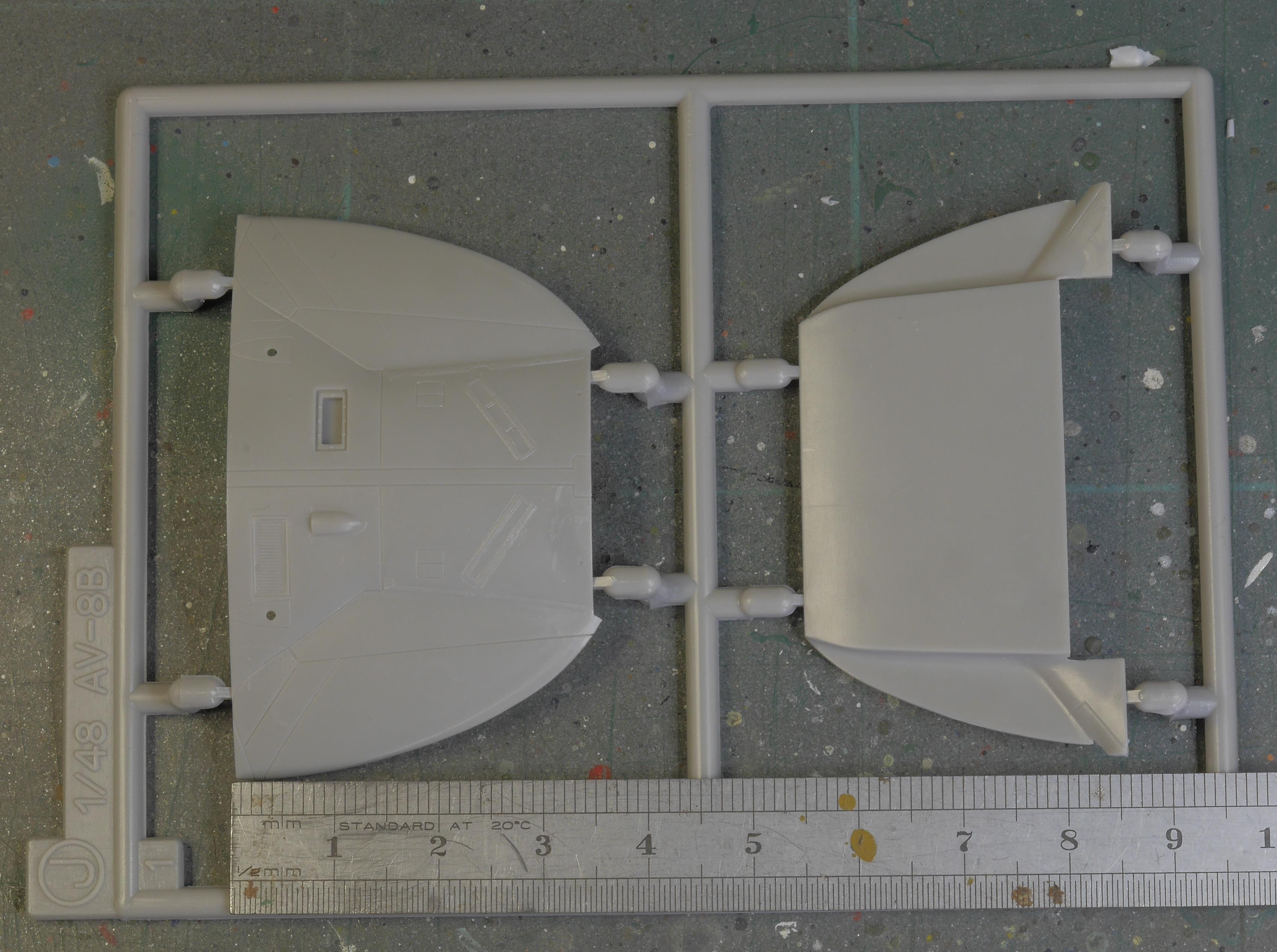
I happen to still have the XIX wing spare from the XIV job a few years ago 'cos I haven't got round to the PR XI yet.
A bit of offering up and marking gave me the locations for the underside camera ports.
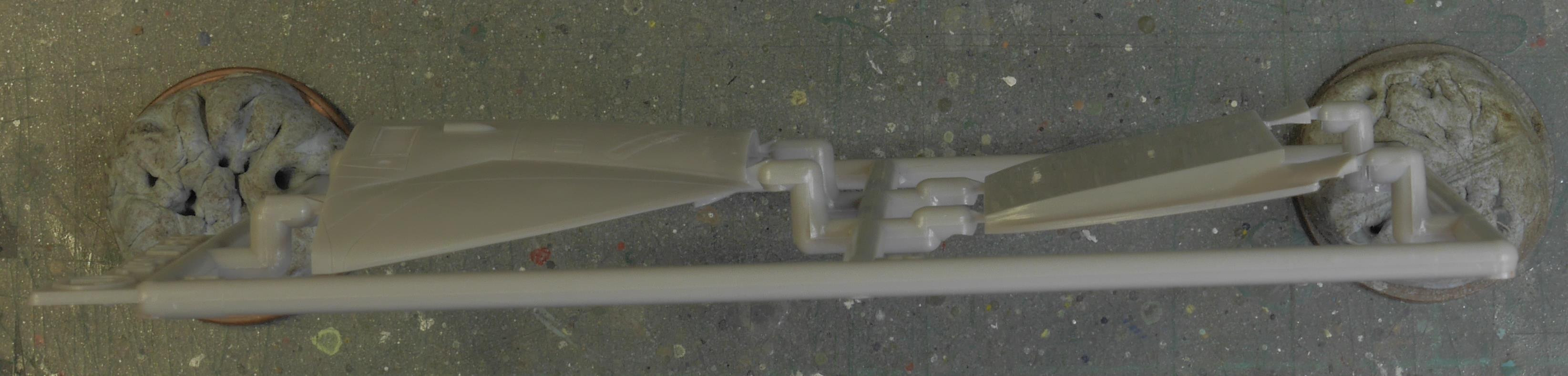
I wasn't too confident of freehanding them so I taped the whole lot together, pulled a hinge drill out of my drill bag and put a couple of pilot holes in the appropriate places.
This was followed by a 6mm drill bit.
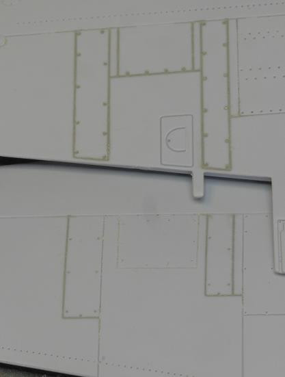
The forward port encroaches on the antenna mounting location.Where would this have been moved to thought I and then went looking for images.My best guess is that it would have been the same as the PR XIX.I don't remember where I found this photo so I can't give appropriate credit.
There will be tidying up to follow.
The unwanted panel lines on the wings could do with another fill but they're nearly there.
Thanks all for looking in,more soon.
-
7
-
-
G'day Andy,if you end up making your own these piccies might be useful.
These links below will give you the largest size images of the above I can generate.
https://bg-so-1.zippyimage.com/2024/03/29/67abac23f0b540faaa50b4f38562b26b.jpg
https://bg-so-1.zippyimage.com/2024/03/29/db303b798af14da1105759052973d66f.jpg
https://bg-so-1.zippyimage.com/2024/03/29/3597ad3332fa4b95defe1e12a322dc75.jpg
https://bg-so-1.zippyimage.com/2024/03/29/976afc73d51be4773fdc7db811c1161f.jpg
https://bg-so-1.zippyimage.com/2024/03/29/be726fa60af2b44da20d2c06be5bc898.jpg
-
I've just had a look through your Bf 110 thread.Pages 2 and 3 have most of your images there but there are missing ones in four posts here,here,here and here.The images that are there are taking a bit of time to show up but that might be something to do with the size of them.
The missing images show up as
in the post and trying the right click open image in new tab gives me
The image URLs are there so they have been generated and I know I've seen the images in your thread 'cos I pressed the like button before I left.
Enjoy this little bit of irony,the two screenshots above have been brought to you via Imgur.
I don't have any answers but I hope the above is useful in sorting out the snag.
-
Might be worth having a look in "Non-album Images",I just have on mine for the first time ever and had the suprise find of some images that I'd thought were safely confined in their relevant albums.And a couple of duplicates that I didn't know about.


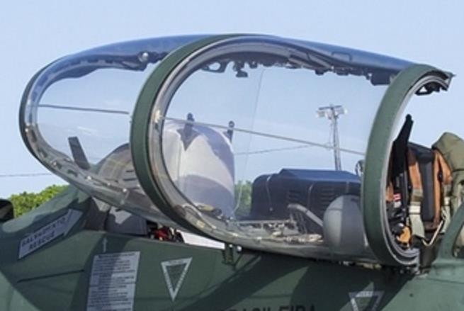
Quick question: How do you make the detonation chord for canopies?
in Modelling Tips
Posted
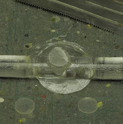
Personally I'd put it on the inside of the canopy.I think that's where it is on the real thing and there is the built in resistance to dusting as a Brucie Bonus.
If you can lay the wire in place and clamp an open end,self closing tweezers are the thing for this,and then use capillary action with the Klear to run it in as the fixative once you've got it where you want it and it stays put you won't go far wrong.The plus to this is that if it goes awry the Klear won't damage the plastic and can be removed using Isopropyl Alcohol or caustic soda which won't damage the plastic either.I've just jerried this up to show you what I mean.
All the potentially damaging stuff can be done where it won't be seen and will be painted over and the excess can be trimmed off once the Klear has dried.Klear is quite resilient when used like this as long as you use enough of it.