

John Aero
-
Posts
3,067 -
Joined
-
Last visited
-
Days Won
1
Content Type
Events
Profiles
Forums
Media Demo
Everything posted by John Aero
-
Tintin's Tiger Moth 1/72 ***Finished***
John Aero replied to Jur's topic in Work in Progress - Aircraft
Tintin marketing actually sells a 1/48 model of the Yellow Tiger Moth but it's around £50 IIRC. I have a Tintin Bus which is about 1/50th scale. Tintin and Haddock are on the back seat reading newspapers.- 74 replies
-
- 12
-

-
I also have this kit, but mine was moulded totally in clear plastic, it's quite brittle but usable with a UK registration decal. Good luck! John By the way if your clear plastic is Slaters Glazing, it won't vacform or push mould. It's only good for flat surfaces.
-
Canberra T.4 from the old Airfix kit: is it possible ?
John Aero replied to Giorgio N's topic in Aircraft Cold War
Giorgio, Thank you for the photo heads up. I will certainly contact you should I wish to use them. In the leading photo the triangular item at top right is in fact the Nav's desk top which is clipped up for access. In the middle photo you can see the the tubular toroidal ring base of the canopy. The second 'dickie's' 3C seat is obviously missing. Even though the Observers seat was not fitted on T.4's the seat rail mount box is. I half remember the large bolts were for ballast weights. There was a massive lump of lead under the Observers nose prone bed in the B.6. I worked on B.2's, T.4's, B.6's, PR.7's and PR.9's but I only ever flew in B.6's. They were the most uncomfortable aeroplanes especially on long trips. If you were in the forth Rhumbold folding seat, all you had was a Lancaster era Chest type parachute. The safety equipment brief was "don't clip it on upside down, cos you'll scratch a big hole in it before you hit the ground trying to find the 'D ring on the right".. John -
Canberra T.4 from the old Airfix kit: is it possible ?
John Aero replied to Giorgio N's topic in Aircraft Cold War
Giorgio. Yes a spare PR.9 nose would be ideal. The Matchbox kit, which has so much wrong with it. would be a good sacrifice. The following which I wrote some time ago might be of some interest. John Tech notes on Canberra’s There seems to be some confusion over the differences between Canberra versions, perhaps this will help. Although the overall lengths may differ and canopies change, the basic nose profiles do not change in plan and side views. B.Mk.2 This was the first production Canberra, powered by the Avon 101 which had the single breech cartridge starter. Three crew ,Pilot, Nav and Observer/Bomb aimer, are all in ejection seats. The Pilots seat at the front slightly offset under the goldfish “bubble top” and two crew in the back. There is also a folding Rumbold seat for a forth crew member with a chest parachute. The nose is glazed with an offset clear vis panel . this is the most common base for all later “funnies” like the T.11, T.17. TT.18 etc. It has radial spoked main wheels. B57A This is an Americanized B.2 built by Martin and was powered by licence built British, Armstrong Siddeley Sapphire engines (J65) There were also local airframe production changes. The later 57’s are a totally different beast based on the Canberra airframe. PR.3 A Photo /recce development of the B.2 but with a 14.5 inch extension for cameras in the fuselage, inserted in front of the bomb bay, which was smaller because of extra tankage and now termed a flare bay. It had a plain glazed nose. T.4 This is the Trainer derivative of the B.2 and is recognized by an un-glazed metal nose cap and the three EJ seats are re-arranged with two seats under the” bubble top” (a pantomime to get into) and one seat at the back. It also has two DV windows in the “bubble”. The nose swings to one side for equipment access at Frame 1 (which is not the first frame). A version for export called the T.13 of which early examples did not have ejection seats for the pilots. At rest the T.4's elevators are depressed because of the locking bar fitted to keep the stick forwards to allow the swing seat operation. Conversely the bomber versions elevators are up when no tail locks are fitted. The seats in the T.4 are 3CT's and are similar in layout to the Mk.2 in the Nav’s position but don't have thigh guards. (Note They are not the same as a Mk.3 fitted in for instance, a Hunter) If you use this info anywhere I would appreciate it if you would credit me as this is my authorship. B.Mk.6 The B.6 introduced the Avon 109 with a new triple breech starter. This has a larger pointed centre body in the intake (the early 3 shot type is quite bulbous) it also has extra tankage in the wing leading edges. This made the aircraft heavier and called for larger stronger four spoke wheels. Variations of the B.6 are the B.I.6 B.15 and B.16. PR.Mk.7 This is the photo development of the B.6 and is a PR.3 extended fuselage layout with the Avon 109 and the B.6 tank wing. Two Crew. RN TT.22’s are converted PR.7s. The clear nose has an optical flat. B.I.8 The “8” introduced the offset fighter canopy and at first glance appears radically different but is really a “boy racer” B.6 with a belly gun pack and wing pylons. The pilot has an EJ seat but the poor Nav does not. Instead he was given a chest type parachute and take off seat at the back and a sideward’s facing sliding seat in the nose, which had extra windows. Both crew enter by the side door as on all previous Mk’s of Canberra. The canopy does not open. The pilots EJ seat is mounted on the pressure bulkhead on an extension of the standard navs EJ rail so he is further aft and higher than in all previous Mk’s. PR.9 This is the GT version fitted with Avon 200 series engines which have a fickle Avpin liquid starter. The wings have extended tips and the chord is extended inboard of the engines on both leading and trailing edges. The pilot has 3CS EJ seat under a B.I.8 style canopy which does open (clam shell style) and the Nav has an EJ seat (type 4 QS) which is buried in the nose. Access to the Nav’s station is via a swinging nose (at Frame One) and the Nav has two tiny windows, a periscope, also a forked stick (to stick notes in to pass them back and up) to communicate with the pilot. The nose profile shape of all basic Canberra’s are the same regardless of which hole the pilot looks out of, despite what some drawings suggest. Hope this helps John Crew access to the T.4. A pantomime in several acts. The ground crewman unlocks the base of the second pilots seat and swings it forwards so, with no-one in the seat, it locks against the panel. (The top of the seat is hinged from a tubular beam so it swings in an arc). The normal first pilots seat is also attached to this beam on the port (Left) side but it has been moved further over to port than in the Bomber versions. The Nav crawls past into the back and straps in. The second seat is then swung completely further aft and locked at a steep angle so the way is clear for access to the port seat from the entrance door. The first pilot climbs in past the stbd seat and straps in. The second pilot now climbs in and straps into the aft angled seat, with his feet braced against the rudder bar plinth. At a signal from him, the ground crewman now moves the seat back to it’s central base locking position, and all three crew are now in position and the crew side door can be closed. At this point the Nav decides he does need a pee after all…….. Canberra brakes. B.1 Wheel brake lever fitted to column centre boss B.2 Wheel brake lever fitted to column centre boss PR.3 Wheel brake lever fitted to column centre boss T.4 Wheel brake lever fitted to each column centre boss. B(I).6 As B.2 but Maxarets fitted. PR.7 Wheel brake lever fitted to column centre boss B(I).8 No wheel brakes on column. Maxarets with toe brakes instead PR.9 No wheel brakes on column. Maxarets with toe brakes instead B(I).12 No wheel brakes on column. Maxarets with toe brakes instead T.13 Wheel brake lever fitted to each column centre boss E.15 Wheel brake lever fitted to column centre boss T.17 Wheel brake lever fitted to column centre boss TT.18 Wheel brake lever fitted to column centre boss Brake details via Ross Mc Neil restorer of Canberra PR.9 XH175 Putting it simply the Matchbox PR.9 kit is quite wrong. The engine nacelles are the wrong shape, especially near the main spar. Also the fuselage is B(I)8 length (too short) and the Frog "8" is PR.9 length for good measure. The tailplane chord on the Matchbox kit is wrong being too wide, but it is an error made in good faith. I found only a couple of years ago that the PR.9 AP Vol One, has the wrong chord length given on the leading particulars page and this was taken as gospel by the late Maurice Landi, of Matchbox. Someone at some time had messed up the AP dimensions. The RAF never noticed and no-one ever checked it ,simply because the Canberra tail chord is always given as a projection to the a/c centre line and this is impossible to measure and it is a dimension which the RAF servicing types would never need to know. So it went unnoticed, until I got suspicious as I used to work on "9"s and started to project lines on photos. This convinced me of the error but by then I had left the RAF. It was confirmed by the Eng WO of 39 Sqn who kindly had some guys measure the chord at the root for me. This confirmed that the tailplane was the same as all other Marks. As the "9" has an un-tabbed powered rudder, unlike all the other Mk's, there is a slight rudder chord difference but not enough to worry about. I provided the basic outline shape drawings to Sword, who did the Hannants kit, They were going to use Czech copies of the Aerodata 34 drawings which though beautifully drawn are inaccurate. That’s it in a nutshell. Regards John- 24 replies
-
- 12
-

-
-
Canberra T.4 from the old Airfix kit: is it possible ?
John Aero replied to Giorgio N's topic in Aircraft Cold War
The nose profile contours of the Canberra is the same throughout the family. The vertical profile also has the same contours as the side profile. What is different is the nose in side profile is angled down from a point just aft of the pressure angled bulkhead at Frame 12 (A/B), so all the frames of the nose portion are no longer perpendicular to the main fuselage centre line but they are now perpendicular to the nose axis. This means that any drawings based on the old Ian Huntley drawing are quite wrong. Even the crew door and the important Frame 1 (One) are canted from the vertical. The transition is cleverly made in the area of the nose wheel bay. A similar side/ vertical profile change happens with the rear fuselage at Frame 27 A/B to frames 30/ 30A/ 31A/B Frame 1 is where all the "funny" noses such as the T.II and T.17 change. This is the same Frame where the T.4 and PR.9 noses are fixed and articulated. Frame (1) is of course not the first frame and Frame holding the clear nose is 1.B The T.4 nose and the B.2/6 and PR's share all the same contours, although the Bomb aiming flats mar the nose curve. The B.I.8 and PR.9 share the very same contours as the others but the pilot's seat is now in the same place as the old navigators ejection seat rail on the pressure bulkhead, but it is now raised much higher. Of course there are major internal changes but most of the frames remain the same, except in the latter versions the Toroidal Ring which supports the old "Bubbletop" canopy is removed. The problem with the old Airfix kit is the nose is too bulbous for a start. John -
I agree with @mhaselden that 43 Sqn Fury aircraft seem to lack the White squares on all the photos I've looked at. This in it's self is unusual in that the Siskins and Gamecocks, both previously flown by the Sqn did have white squares. John
-
That interior is superb. John
-
Certainly another excellent approach. I'm a confirmed cabinet scraper fan for vacs, I have a selection and I've made a sharpening jig with a honing Steel to turn the edges. John
-
Grass hopper says "The vac canopy has a centre rib, can you not cut carefully along that line and "lose a bit" john
-
Terrible Heller 1/72 Bloch 174 moulding
John Aero replied to AltcarBoB's topic in Work in Progress - Aircraft
At the time I mentioned, Heller were also moulding Airfix kits. because they were under the same umbrella company. My comments were nothing to do with Heller designs, choice of subject, marketing or nationalism, but a period of time when their production standards were poor hence the Aifix Concorde where I was told parts of the fuselage were made in different factories and it's subsequent poor fit.. Post 56, Read the thread title, the complainant had cause to complain. I gave a valid reason. I too have some perfect older Heller kits and I built a Bloch 174 as a later Aeronavale aircraft many years ago. John -
The aileron links are in line with the single strut because IIRC, the top and bottom aileron connecting link runs up through the strut fairing. John
-
Martian And The Canberras From Mars
John Aero replied to Martian's topic in Work in Progress - Aircraft
Late to the party, T.4 front seats Mk.3 CT, rear seat Mk.2 CA. Yes the T.4 nose can swing for quick access or be totally removed on a special trolley.. As to Canberra's tail sitting, yes they will, if you defuel the front tanks first. I recall walking past A.S.F at Coningsby early one misty morning circa 1961 and seeing a B.6 sat on it's .... John -
Hi Moa, Yes I know but Patric asked a question about the gap. You attract so many people to your builds that it's a good vehicle for General information.🤓 John
-
The Japanese inter-war flying boats were all developed from British and German (Rohrbach) designs. The British aircraft started with the Felixstowe but most metal hull designs were based on the Southampton, Shorts designs and Blackburn aircraft If there is no other info forthcoming then I suggest that the interiors will be very similar to these types. I have the five volume Japaneses Aircraft Encyclopedia, but their are no cockpit photos. John
-
Humor apart, 😀 I've just tried Slater's hard red plastic rod and this is much more rigid than normal styrene strip. I've reduced a piece of their 50 thou round rod to a teardrop section of 50 thou by 30 thou around 5" in length mainly by working from one side in minutes. John
-
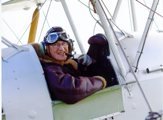
Beautiful work as usual. Just a note of the tailplane trim on Moths. There is a small gap between the base of the fin and the top surface of the tailplane. See post 94) This gap does not change in flight as the tailplane incidence is set by the ground engineers, the gap varies by type. See bottom left of the drawing. Trim is achieved on the elevator by a spring bias on the elevator Bell crank behind the rear pilots seat and is set by the quadrant thingy adjacent to the rear pilots left thigh. John
-
Benes-Mraz Be.150 Beta Junior (Legato 1/72)
John Aero replied to Andrew.S's topic in Work in Progress - Aircraft
Lovely model in splendid pre-war markings. I have the drawings for these from L&K as well as Nemecek's books, If they ever come to Telford they're welcome to land at Stackton Tressel Aerodrome. 😀 John -
1/48 Fairey Flycatcher (Armory)
John Aero replied to Gisbod's topic in Ready for Inspection - Aircraft
Nice work, Here's the real thing. John -
I'm not Coping very well either, as the blade is the right way round. John
-
I have sent the dimensioned drawings I mentioned to Mechanic. I'm not sure what's happening to the Flight Archive as it's been down for some time. John
-
I agree, I have a Swiss Jewelers saw which is adjustable for blade length so if you break the blade you can still use the longest piece. It also has the screw tension-er as well. The Fretsaw simply allows you to cut further into sheet material, for which I tend to use one of my mechanical Fret saws. John Top Left a Swiss Jewelers/Piercing saw, Right a junior hack saw, Bottom left a standard Piercing saw and bottom right is a Coping saw, (with the blade in backwards). A fret saw is just the same as the Piercing saw but the frame is about three times the height.
-
Just another comment on the saw frame types. Coping and Hack saw frames and blades normally use small pegs to secure the blades. These frames are no good for the above process, Piercing saws and Fret saws use a screw clamp at each end of the frame to hold the blade and these will also hold other items such as the plastic strip and wire, Fret saws have a much bigger/taller frame than Piercing saws. Both have their uses in model work and are relatively cheap. High quality piercing saws often have an adjustable width frame. The latter saws are fitted with blades by pressing the saw outer clamp against a bench to spring the frame whilst the blade is clamped at the outer end and then at the handle end. When the pressure on the frame is relaxed the blade is now under tension. As Melvyn said the blade s of all these saws must never be used loose. John
-
Bristol Berkeley - 1/72 scratchbuilt - Finished!
John Aero replied to Jonners's topic in Work in Progress - Aircraft
Well done Jonners. John -
I won't commit the whole coil.😜 As you see there's quite a bit of it. John
-
Thanks Dave,, I will play further. So, if I heat the coil (or a few Metres of it) and then stretch it, it will then straighten? John
