

John Aero
-
Posts
3,067 -
Joined
-
Last visited
-
Days Won
1
Content Type
Events
Profiles
Forums
Media Demo
Everything posted by John Aero
-
This one is a difficult one. I spent ages thinking about the complicated geometry involved as the wheel has castor, camber and toe in and the angled pintle make the leg go from vertical forwards sweep, to rearwards hoizontal sweepback. Also how does the wheel lie in the bay? Then if you look at the door fairing ,it projects more at the front. But this changes as the oleo extends. All the engineering drawings show two staggered elipses. Short answer, it's eliptical, cos I found a nice photo of a Mk.XII in a vertical bank which illustrates it nicely but I forgot to bring it home with me. Cheers John
-
Anybody actually got their hands on the SH Anson yet?
John Aero replied to Potato Pete's topic in Aircraft WWII
Pete probably hasn't entered them yet and he is at present on holiday. As the Anson is still current we can supply any of the parts separately, just give us a bell at the workshop or an email. John -
Hi I believe that the kit is wrong because it also disagrees with the outlines in the Robinson drawings and with the outlines in some of the Supermarine drawings which have been used in some publications and the under rated Cox drawings. So I'll go with Arthur. I am not qualified to rate the Mustang drawings or indeed comment on them but so far I'm happy with the Spitfires. The fillet shape is quite minor. Yes I have the very detailed "multiplex" drawings for the Spit, which I have no problem with as I know that they have been derived from works production drawings and I have sufficient measurements to hand to check. Cheers John
-
This is my recommendation for the areas to be thinned before assembly. By the way the assembled shot is only taped togethether I don't glue them as then I would have to paint the bloody things! John
-
Sorry, I didn't make myself very clear. The pics are the Mk.V which does need more reshaping. The new Mk.1 has had some slight re-tooling done (by Airfix) but the thrust line has not been lowered (as it has in my example in the photo). I have just done a quick test on my Mk.1 and I've sanded of the top of the nose a little and taped the lower cowl in position so I can check the spinner backplate against both. At worst a thin sliver of card will restore the balance if you take off too much. On the Mk.1 you don't have to remove as much material as on the Mk.V, so beware. The Spit has a subtle curve between where the rocker bulges finish and the spinner backplate. John
-
Note the Mk.1 nose has been reshaped a little but not lowered. With the Mk 9 you need to remove some plastic from the bottom of the top cowl piece, but taper it, from none at the back ,to about 1mm off the front. Then reshape to the spinner. The Mk.9 wings also need thinning, so once more the greatest thickness is 7mm. John
-
Hi Coll No both are in fact the Airfix Mk.V with a tamiya spinner, but are so similar to the new Mk.1 as to make little difference as an illustration on how much to reshape (as on the picture right side). John
-
I have just found time to have a look at the new Mk.1 and though it's ancestry, in that it is a derivative of the the old Mk V, is plain to see, there have been many changes. I am using a mix of fullsize dimensions and the works blueprints based (unpublished)drawings I obtained from Arthur Bentley and I trust them. The fuselage is very good and from the firewall back it matches on all points, windscreen ,door, rear of rear view panel etc. The rudder is of correct chord and shape, with the only very minor niggles being the shape of the fin/fuselage fillet and that the rudder hinge line is 0.5mm too far aft. The wing fillets are good and of the correct width. I have long maintained that the nose contours(ie thrust-line) on these Airfix Merlin family Spits are too high and although some reshaping has been done the Mk.1 nose plate is still too high by .75mm. Ok most folks won't notice it. The wings. In 1:48 scale the Spitfire wing at it's thickest point should be 7mm and this new kit comes very close. Shapewise, the trailing edge is very good. The leading edge at the centre gun positions is a touch too "full" and again at the very tip where the nav light is. The wing root angles on model Spits are all different and these follow the pattern but not the drawings. I don't like the silly fabric sag, but a film of filler will sort this . The panel lines are fine. The trailing edges though much improved will still benefit from thinning down on the insides. The shape of the D.H. prop blades is good but the Rotol not so good and the Watts two blader should look the part when assembled but watch out for the tips sweeping back. So as far as the basic shape goes, Airfix have done well and remember that this was done under the constraints of the old company and so as such it is not a new Hornby kit. Just my observations. John
-
We're getting there, so it won't be Crowbars at dawn. Cheers John
-
Thanks for the feedback Dave and Edgar. The panel line (really Join line) I refer to, was, as I pointed out previously usually filled and painted over, so it's invisible on most 14 variant pics but I am finding more and more where it can be diserned. The normal rudder post (fin) height for the early Merlin Spits is 58" (ish) and so I suggest the rudder post height for a 14 has to be nearer 61" as the extension fin tip is about 2.75" deep. The chord for a "big rudder" on the lower edge of the trim tab is 33.2". Cheers John
-
Edgar No arguement just logical investigation into a simple solution. ) Look very closely at the top pic of LA215 and just above the stencilling-there is the join line which by the way was normally flush filled, but on LA255 it had become loose which is why I noticed it. and memory tells me it was made from wood. If you have a pic of the 14 that went to Canada for cold weather trials in it's later natural metal racing guise it can be seen also. Cheers John
-
Edgar Whilst I accept that 1946 was probably the introduction date for the "big" rudder I still maintain that it was possible to retrofit it because the fins of Mk."14" type fuselages had been built up in the first place. The fin tip of the "normal 14" has a chord of 14.25" and the fin tip of the Mk.14e (big rudder) at Manchester which I measured is 16.25" chord. If one takes the line that the fin heights are the same on 14s and 18s then the fin leading edge of the 18 has been extended giving a much broader fin,which I feel is clearly not the case. Cheers John
-
Edgar It would appear from these discussions that the "big rudder" originated with the fitting of the contra prop to the Mk.21 (and not with the 18), and there is a photo of LA219 dated September 1945 fitted with this wide chord rudder. It's becoming obvious to me that with the larger chord requirement for the contra prop a/c came the need for a larger (both weight and aerodynamically) counter balance horn and this was easily acheived by reducing the fin height back to the original rudder post height. Over John
-
Hi Edgar Interesting as always but was mod 1672 introduced as a mod specific to the 21 (contra) in which the mod "used" the (possibly) exsisting 18 rudder, or was this an introduction of the broad chord,big horn rudder to the Spit in general?. I'd suspect the former, remember all 14 airframes would have the "false" extension to the fin tip from build. Regards John
-
Hi Bill No need to change anything except the one little panel line for a 14.19,21 (to be 100%). It's the shape of the 18 and FR14e rudders which is always drawn wrong. Tommy Atkins (Metal kits) did explain to me once (he flew 21's with No 1 Sqn), why the contras were fitted with the larger rudder . Apparently propeller gyroscopic force is eliminated but torque is not and on take-off at low air speeds a dropped wing is recovered with the rudder, as coarse use of the aileron to lift the wing introduces induced drag compounding the problem. Here is my old 21 from 1 Sqn days I fitted the four slot wheels as the BB flight stole the 3 slots for their 19's. Please note that the 14 rudder tip in my original sketch is slightly too high. Arthur Bentley and I are close but not totally in agreement over some shape aspects of the 14/18 rudder differences but the drawings I have of Arthurs are preliminaries. John
-
There is some confusion with the rudders fitted to the Mk.14 and 18 Spitfires. I find that the Morgan/Shacklady "bible" is often less than helpful and sometimes irritating. As Edgar mentioned in a previous post (on contra props) the 14/18 fin/rudders areas are given as the same. This is not so and this "red herring"is the cause of some confusion. The 14 fin went through a considerable change in area and the only real reference given in the"bible" is a sketch showing an interim straight leading edge modification and it omits to mention that the height at the rudder post was increased by almost 3". The standard rudder post height of all the earlier Spits was 58". The extra 2.75" fin height increase was achieved by fitting a "block false tip". The Mk.18 had a broader chord rudder and a deeper horn balance. This rudder was also fitted to other Mk.14 based airframes,( by the simple expedient of "removing the block") such as FR14e, 19, and the Mk.21 when fitted with a contra prop. This illustration I have cobbled up might help. It is the tail of an FR.14e and I have superimposed the outlines of the Mk.14 and Mk.18 rudders on to it, the white area is the "block" . The blue outline is the 14 and the red 18. The join line (lower edge of the block) seldom shows up on photos and is often shown as a panel line in drawings but too low down, a mistake repeated on my own Mk.21 conversion as this was made originally to the Cook drawings. John
-
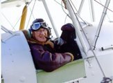
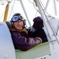
Bone domes were silver and were seldom any other colour,they were worn over a separate Blue /grey flying helmet (visible in the picture), the visor was black perspex but often had a black cotton cover over them. The suits also had a blue /grey cravat. (Scarff) attached to the inside of the collar I still have the white leather gloves. Later the gloves went to green but were replaced by white as the pilots had difficulty seening their hands in the cockpit. John
-
Grey suit and silver "bonedome", white gloves and yellow orange Mae West. John
-
Anybody actually got their hands on the SH Anson yet?
John Aero replied to Potato Pete's topic in Aircraft WWII
They are available now, but I will have to check the price with Pete at the workshop on monday. Likewise all Anson kits will have these as standard from now. John -
Mk.1's. From my own collection. John
-
Anybody actually got their hands on the SH Anson yet?
John Aero replied to Potato Pete's topic in Aircraft WWII
Photo of new resin Cheetah and cowl, (also see above post) -
I'm glad you spotted the spinners, just one of the many inaccuracies in 'all' Hornet drawings and kits. The fullsize spinner dia by the way is 29". I am to to co-author, with the owner of the cockpit, what we hope will be the definative technical book with the first very accurate drawings, dealing with these lovely aeroplanes. There will be a few surprises with especially dimensions. John
-
The bar behind the headrest is an adjustable headrest support for catapult takeoffs. John
-
Are you still after the Hornet seat gen? John
-
The Contrail kit was made by Gordon from the plans in AFP and the post war versions had most of the plans redrawn and so this is about the best you will get I'm afraid. John

