


WorstKaasScenario
-
Posts
9 -
Joined
-
Last visited
Content Type
Events
Profiles
Forums
Media Demo
Everything posted by WorstKaasScenario
-
1/72 Bloch MB.162
WorstKaasScenario replied to WorstKaasScenario's topic in Work in Progress - Aircraft
So, I've been working on the nose section for a bit. I started with the outline of the nose, the framework and the addition of an access hatch in the floor. I haven't created the actual hatch yet. The frame was a bit of a pain due to the curvature, but I think it came out nice. I also opted to use denser lattices, as I think they might be too far apart in the rear section. I don't fancy removing them all and doing it over, so I'll leave the be in the bomb bay and gunner compartment. The front decorated. Because that was the last part for the coarse details, I've started with the fine details, beginning in the nose. The layout is quite simple, a small table, a chair, some electrical equipment and a map bag. I might add some more random bits and pieces. The wiring I might do after painting, but I'm not sure yet what will look better regarding shading. Oh well, I'll just leave it for now. I've also started with the canopies. As shown here I've created a small connection ring. The clear plastic is quite flimsy, and I didn't want to mess up the fitting when the plane is assembled. The ring makes sure that the shape of the nose is forced to that of the fuselage. It also adds some rigidity to help with alignment. Luckily the size is correct, meaning I don't have to heavily edit the fuselage to fit a too small or too large glass nose. However, not all is good. There are some poorly embossed panel lines on the nose, which are neither in the correct position, nor straight. As you can see, the very front part is too large compared to the real glazing. Also, the bottom rear window extends a bit more forward, which also isn't recreated by Broplan. Considering this I decided to sand off the panel lines, hope that they aren't too pronounced on the inside and polish it back up. The quality of the other canopy isn't much higher. Still the same shoddy lines, and worse, wrong shape. As is visible on the photo above, the real canopy consists of 14 windows. The six roof windows are aright, but the kit has 4 front facing windows, where only 2 exists. It also lacks the two tiny windows in the bottom middle. Additionally, the middle windows start to point slightly inwards in the real plane, while they're parallel with the fuselage in the kit. Because this can't be fixed, I've decided to scrap the canopy all together and create a new one. I've never made vacuum formed parts before, so wish me luck. I've 3D printed a master, but I don't know if i can use that directly as the softening point of PLA is lower than that of polyester. The heat transfer might be slow enough to make it work, but I might need to treat the master with something, or make a resin copy first. I also don't know by how much i need to scale down the master so the canopy is the correct size, so I start with one and create a new one based on the results.- 12 replies
-
- 4
-

-

-
- Bloch MB.162
- 1/72
- (and 1 more)
-
1/72 Bloch MB.162
WorstKaasScenario replied to WorstKaasScenario's topic in Work in Progress - Aircraft
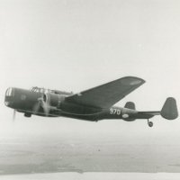
So part three, the rear section. The MB.162 production model had a planned defensive armament of two 20 mm Hispano-Suiza HS.404 cannons in a dorsal an ventral turret, and two 7.5mm MAC 1934 machine guns in the waist. These aren't on the prototype however. There are some small windows where the waist gunner would be. The HS.404 turrets can be seen on the only contemporary drawing of the plane. German captured aircraft showing the waist gunner windows. Also note that the markings were removed afterwards. Contemporary drawing showing the dorsal and ventral turret. I managed to get my hands on some resin guns, as the kit has none, and I don't think my printer can handle those. The Hispano's don't have magazines, however some MG FF's I have lying around have very similar magazines. I started by cutting out the hole for the dorsal turret, directly behind the wall, following the shape of the canopy. below that I placed a thin piece of plastic card with a circle cut out for the gunner Nothing fancy (yet), just a very basic turret. The material for the ventral turret removed. This one will be more of a bathtub, completely open. I don't know yet if I will open up the canopy. The waist gunner windows created. I also placed the same patter framework as in the bomb bay. Because the windows on the prototype seemed rather small, and didn't line up neatly with the framework on the inside, I decided to make them slightly larger. The wing root indentation was covered up with some plastic boxes. What are they? I don't know yet. How the plane was entered is a complete mystery. No photograph I've found shows any indication of an entrance. The left side is pretty well photographed, so it's most likely not there. The front section from the right doesn't show a door either, so that leaves two likely positions, back right, and a ventral entry under the cockpit. I'll add both, since my current cockpit design doesn't leave much room for the nose to be accessed from the rest of the plane. The interior is clearly visible from the outside. Bonus points if you can spot the three places where I removed too much material and had to repair it. That leaves pretty much the nose section for general construction, plus I will spend some time making sure the canopies fit well. I've also pretty much caught up with my current progress, so updates will slow down- 12 replies
-
- 5
-
-
- Bloch MB.162
- 1/72
- (and 1 more)
-
Checked it again, this time my browser was messing it up. Cleared cache and now it's working fine. Thanks for the help everyone!
-
Well after forgetting to port forward and spending way too much time debugging, I switched over to https, Let's encrypt certificate works and redirects are setup. The images however still aren't accepted. Did I miss anything? Anyone got more idea's? At the time I was setting up https, so the website was offline for a bit, hence the timeout errors. I've tried multiple different pictures, but each has the same result. Reuploading also has no effect.
-
Yup, with an aluminium underside. A bit back in the thread was stated that there was no information on the wheel bay of the CW-21B, but in this thread https://www.secretprojects.co.uk/threads/curtiss-cw-21-demon.8991 a drawing of it was posted. Again, I can't vouch for it's authenticity, but it would be a weird drawing to create as a fake, and the poster there is as far as I'm aware a good and reliable source. The source of is also posted, but lumped together with different images so I don't know what's from what, with a bunch of them not available on the internet. Might be a lead. Also when compared to what is visible on photo's it seems accurate. Of course this picture is easily findable with a quick google search, so it might already have been known. Ignore this, I was wrong. Other than that I don't think I have any spicy information on this plane.
- 60 replies
-
- 3
-
-
- Interceptor
- Dora Wings
- (and 1 more)
-
I've got this colour photograph lying around which clearly shows it orange. I remember it being an original colour picture, but I'm not 100% sure and I can't find out where I got it from.
- 60 replies
-
- 8
-
-
-
- Interceptor
- Dora Wings
- (and 1 more)
-
Hello, Recently I've decided to also start posted my progress here. Now because I already have my own self hosted WordPress website where I already put my models, I decided to use that for image hosting as I upload my pictures there anyway. Now the weird part. If I paste the URL with domain name it isn't recognized as an image and stays as a link, even with the "insert image from URL" button it doesn't work. The link just turns red. http://emmasplanes.com/wp-content/uploads/box.jpg However if I the site's IP address directly it does work fine: http://80.114.175.70/wp-content/uploads/box.jpg will work as expected: Is this something I should configure on my servers end and if so, what and how? Or should I just keep using the IP method?
-
1/72 Bloch MB.162
WorstKaasScenario replied to WorstKaasScenario's topic in Work in Progress - Aircraft
I generally like going all out with my models, so that includes a bomb bay. Regrettably there is very little information on the internals of this aircraft, and no photo that I could find had a high enough resolution for a discernable bomb bay. Aero Journal notes the plane had 4 "casiers", bomb racks. Now the plane is also stated to have a maximum bomb load of about 3.000-3.600 kg, which would mean that the plane would be severely under maximum capacity if it would only carry 4 500 kg bombs, the heaviest bombs in the French arsenal at the time. Therefore I interpreted this more like 4 bomb bays, similar to the Consolidated B-24, which has 4 compartments in which multiple bombs can be suspended. The design consists of four bomb bays/racks, separated with a walkway down the middle and the main wing spar across. The design is inspired by the B-24 and altered to fit the needs of this aircraft. Each bay is sized to fit two 500 kg bombs, or multiple smaller ones. I do actually have some resin bomb racks for a B-26 which ill probably use here, but that will have to wait until I start with detailing. There is also an extra beam on top to hide the seam line and strengthen and align the fuselage halves I started with a 2nd bulkhead slightly behind the cockpit, followed by a thin sheet wrapped around the inside to hide the indentation caused by the wing roots. The walkway and the rear bulkhead in place. It was at this point I really started to struggle with the poorly shaped fuselage halves. The fuselage is split slightly to the right of the centreline and the height of the bomb bay isn't consistent. But after lot's of measuring and wasted parts I think I got as good as possible. That's one big advantage of 3d printing: If you mess up a part, you can just reprint it. Things are still slightly wonky due to the pieces being aligned to different parts of the fuselage, but when looking from the bottom it isn't noticeable. The seam line visibly off centre. Next was the air frame and the main spar. I've also added additional beams on the outsides of the bay to better hide the transition between the interior wall and the opening of the bay. The bomb bay in all it's glory as it will be visible when all is finished. It's not perfectly straight, but without a good foundation it will never be. I accidentally cut the right bomb bay too large, which I fix when the halves are glued together. Just as with the cockpit, I will add details when the basis is finished. Next part, the gunner compartment.- 12 replies
-
- 3
-
-
- Bloch MB.162
- 1/72
- (and 1 more)
-
Hello everyone, After for lurking a few years, I've decided to my progress with everyone. It might be interesting to some as the MB.162 isn't the most well known aircraft. As far as I can tell I'll even be the first to post about a scale model of this bomber on the internet. I actually stared this model a bit back so there will be enough content for the future. I will however The MB.162 was a French, four engined heavy bomber designed just before WWII. Three prototypes were constructed, of which one was finished and test flown before the German invasion. After the bombing on Villacoublay air base, were the prototypes were stationed, the 1st prototype was evacuated to Bordeaux, while the other two were destroyed in the attack. This was however in vain, as the Germans captured the country two days later. The plane was subsequently put into storage for two years. In 1942 the resumed testing the plane. It showed up sporadically in inventories until 1944, when it was presumably lost near Berlin in one of the many bombings. Very little information on this aircraft has survived the war, which is a blessing and a curse. I always want my models to be as accurate as possible, but with literally no information on the interior as far as I can tell, that will be difficult. At least no one can prove that my build is wrong either. There is a nice article in Aero Journal №32, from which I got most of my information. The plane is also featured in the video game War Thunder. However as some parts of their interpretation are straight up impossible, I won't take their interior design as truth. I however did take some inspiration from it. The kit itself is your very basic, overpriced vacuum formed kit. It's made by Broplan and bought it a while back. I always had a fascination for the more obscure aircraft of the 2nd world war, so this plane was right up my ally. Some injection moulded parts are included as well, but they're of horrendous quality, as are the decals which are pretty much unusable. I do have some post-war Aéronavale roundels from an Dornier Do-24 build, however I might just spray paint them. I'll probably decide the scheme when I get there. For scratch building I've decided to try using my 3D printer (just an ordinary FDM printer, no fancy resin). I did try to fully 3D print an aircraft kit before, however the fuselage proved too much to do. Anyway let's get started. I started out with cutting out the two forward fuselage halves, as is pretty standard. As there a no reliable plans of this plane I can't really check the contour but rough shape looks fine and the halves line up nicely without the need to force them for the most part. . I did however notice that the left wing is slightly, but noticeably more to the front. There is also a severe lack of surface detail, that is, there is none except quite a few pits. As said before, I tried to 3d print the parts this time, instead of cutting them prom plastic card. Does it save me time? No. Do I still need to manually file the parts into the correct shape? Yes. Is it easier to create fine, symmetrical details such as the framing? Maybe. But it's a new challenge and honestly quite fun. As seen in the 2nd photo above, I started with the included vacuum formed parts for the basic shape. Tape them to your screen and trace the outline. From there alter the shape until it's good enough and manually file them to the correct shape. It's here that I also discovered that the fuselage halves are not quite symmetrical. They're however close enough that I can just mirror the parts and sand them down accordingly. The details such as the door and framework are of course my own imagination. The rear part of the cockpit is finished. Trying to get the shape of the instrument panel correct was a bit of a pain, but I got there eventually. I've decided to let the cockpit be for the time being and focus on the big parts such as the bulkheads and flooring before doing the details. In the end, the fitting is pretty tight and without gaps which is nice. There are be some print lines visible, however I'll try to remove them as best as I can and print the parts in such a way they'll be on the hidden side if possible. As this part is running quite long already, I'll stop here. Next part, the bomb bay.
- 12 replies
-
- 6
-
-
- Bloch MB.162
- 1/72
- (and 1 more)