


Iain Ogilvie
-
Posts
4,848 -
Joined
-
Last visited
Content Type
Events
Profiles
Forums
Media Demo
Posts posted by Iain Ogilvie
-
-
On 12/7/2022 at 4:48 PM, Steve McArthur said:
If he switched from FDM to SLA printing for all parts it might be worthwhile.
And that would send the cost skyrocketing - as well as making things a lot heavier and bonds more brittle.
FDM is absolutely the right process for the larger kits/scales - with details done on a resin LCD/SLA printer perhaps. I use both an FDM and LCD printers here - playing each to their strengths. I even have a complete 1:32 Boeing P-8A Poseidon I'm working on - airframe parts printed on the FDM printer in HIPS - strong, light and easy to work with. I'll do the detail parts on my resin printer. There's no way on this planet I'd print something that size in resin!
The layer lines really are not a big issue - if you have a little patience, a can of primer and some abrasive material to hand.
I'm building his 1:32 Andover at present - and really enjoying it - probably the most modelling 'fun' I've had in years. Far easier than a vac, or resin kit - especially for something rather large.
The value is very good IMHO - given that you are getting something almost unique that would be almost impossible to justify by any other means.
Expect injection moulded quality and you'll be disappointed. Expect a canvas of basic shapes that will need working on and you might be pleasantly surprised - I was.
")
Iain
-
 1
1
-
-
If you're doing any major sanding with the ABS then 60 grit glass paper works brilliantly - a lot faster than wet and dry - and with more 'ooomph'/'authority' to smooth out high spots.
Followed up with 400 grit wet and dry and ready for more primer.
Nose shape almost there - have sanded through surface of the prints on either side - leaving holes to be filled - but I expected that - and an indication that the cross section where the two parts are bonded is now closer to the shape on the real aeroplane.
From this:

To this:
Still some finessing of high points/curve blends - but these are to be expected.
More when there's more, but hopefully of some use to other Andover builders (in any scale) - and anyone building a model from a 3D Printed set of parts...
Iain
-
11
-
-
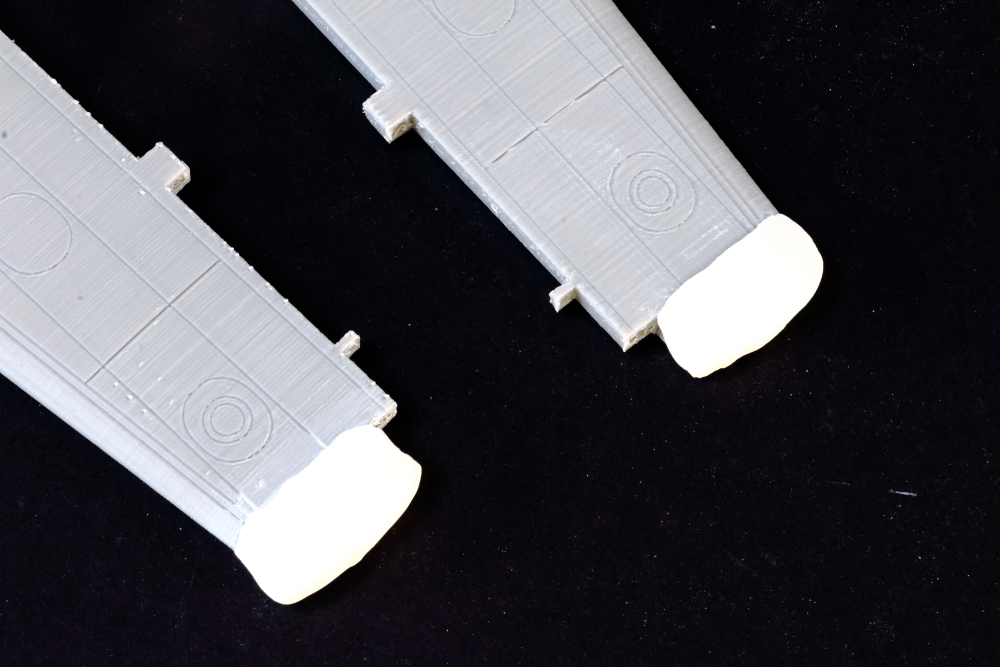
Wing tips filled underneath with Milliput Epoxy Putty - this will be re-profiled when I sand the wings back - but I need to box in the flap areas first:
Nose primered with automotive primer (in this case my usual Halfords brand):
Ready for *lots* of shaping to blend everything together and get some smooth curves - the need for this is very obvious when viewed from above.
Have fun!
Iain
-
2
-
-
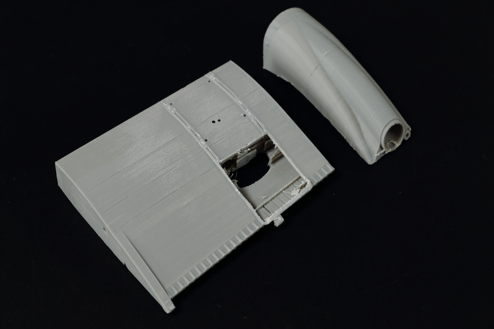
Another area that I've been able to progress with now I understand the routeing of the nose intake ducting, is the nose.
The outer/external part of the intake has been removed and will be replaced by a vacuum-formed one later in the build.
The opening in the nose where the trunking would be has been filled with Milliput epoxy putty - and an opening shaped wet with a cocktail stick - this will be refined later:
The nose was then filled with lead shot (the stuff I use is sold as diving weight material) - and filled with casting resin to form a meniscus slightly above the level of the nose component.
Once cured, this has all been dressed off a-la-vacform by circular sanding on wet 400 grit wet and dry paper, followed by 800 grit:
Same sanding process applied to the cockpit section - to ensure a surface that is true, and clean of paint etc..
Dry fitting looked good:
And bonded with Plastic Weld - *very* strong assembly:
Good that it's strong as I'm going to be doing some heavy re-shaping - especially at the sides...
I can almost hear those Rolls Royce Darts spooling up now!
Iain
-
3
-
-
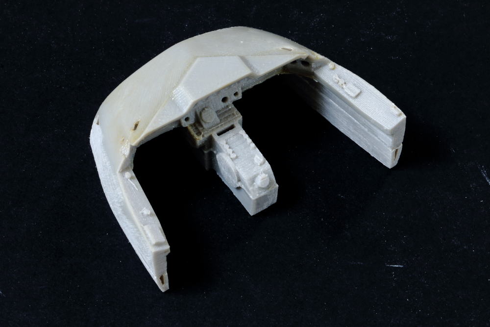
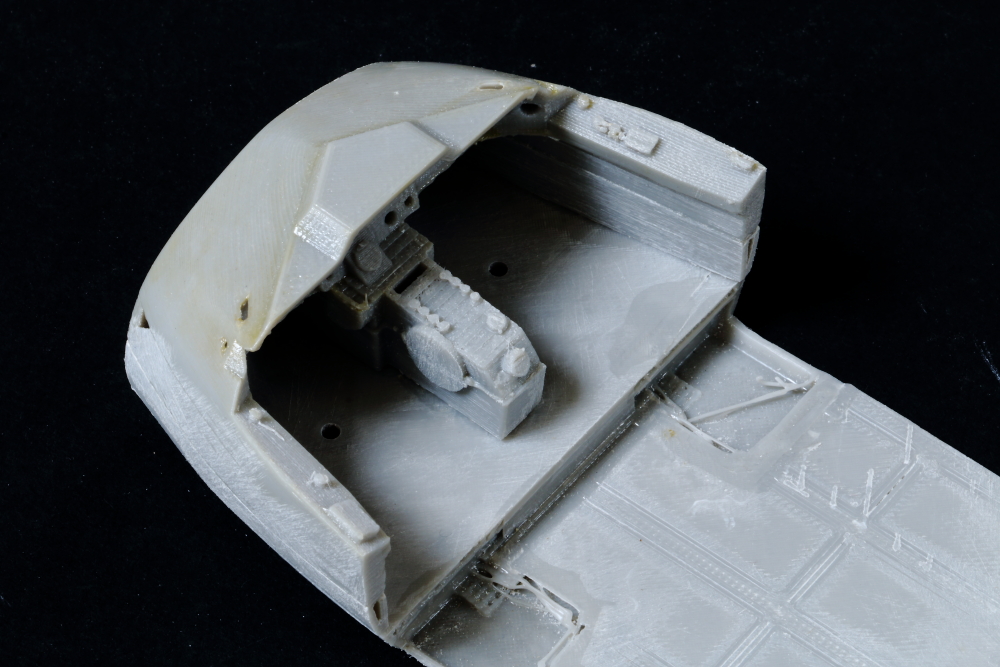
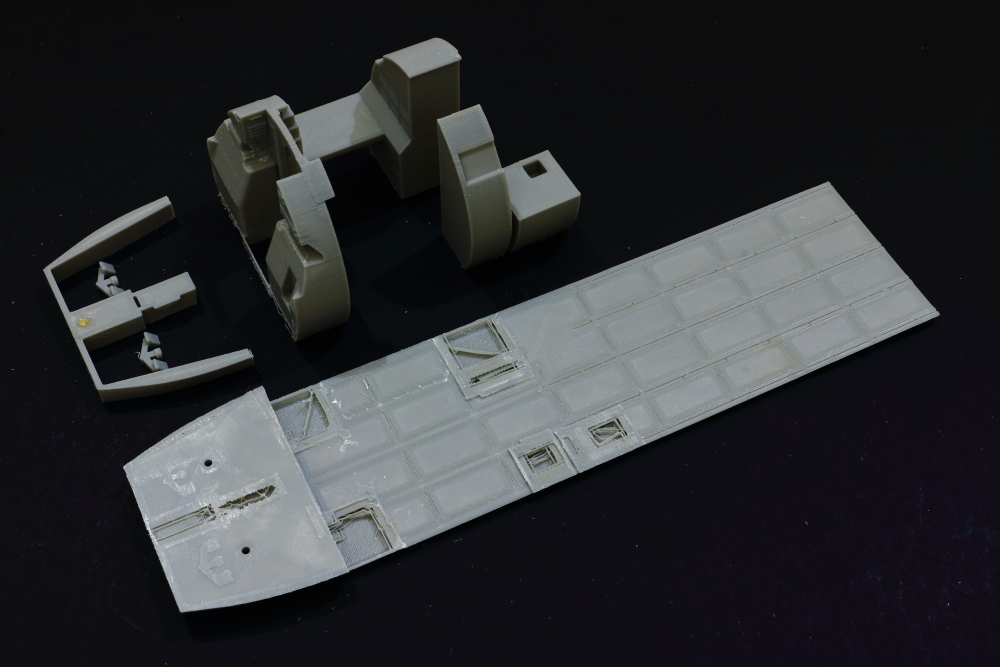
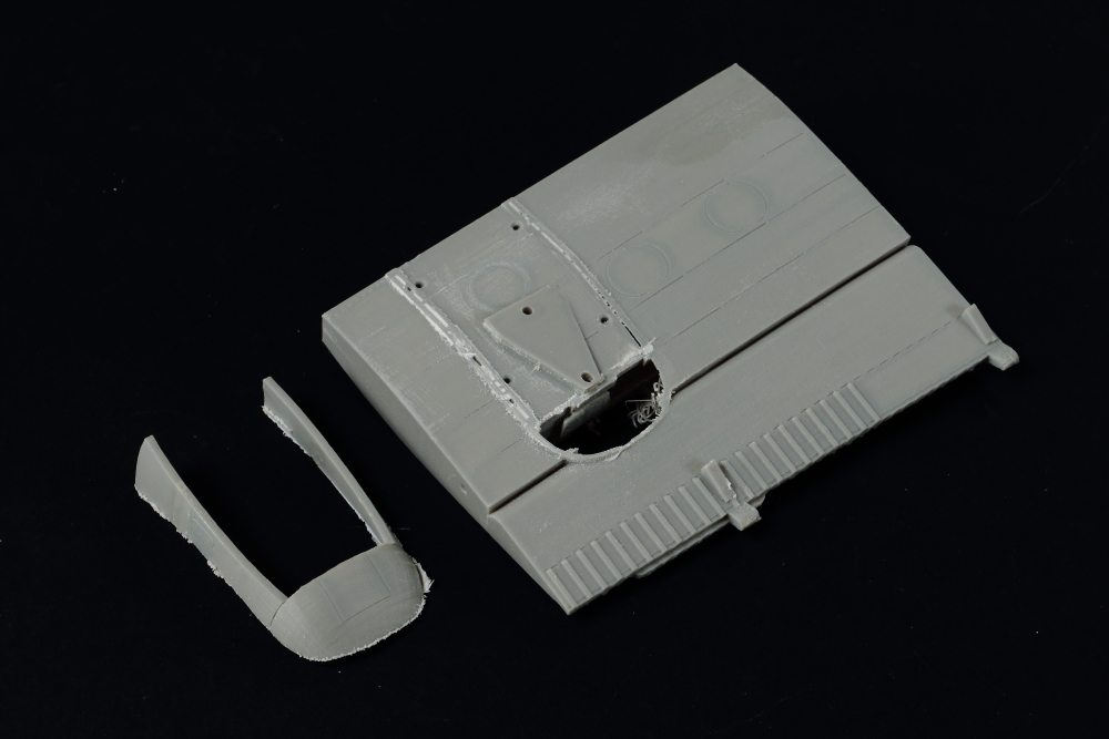
Work commenced on smoothing the interior surfaces, prior to detailing and paint:
Front/rear sections of the 3D Printed floor bonded together with Plastic Weld and the surfaces dressed off - these will be 'skinned' with styrene sheet prior to adding surface detail - some holes where the printed internal structures were removed...
Upper and lower 'cockpit structure' bonded together - shapes are pretty good - but all surface detail will be removed/replaced:
And loosely placed in position on the flightdeck floor:
Iain
-
2
-
-
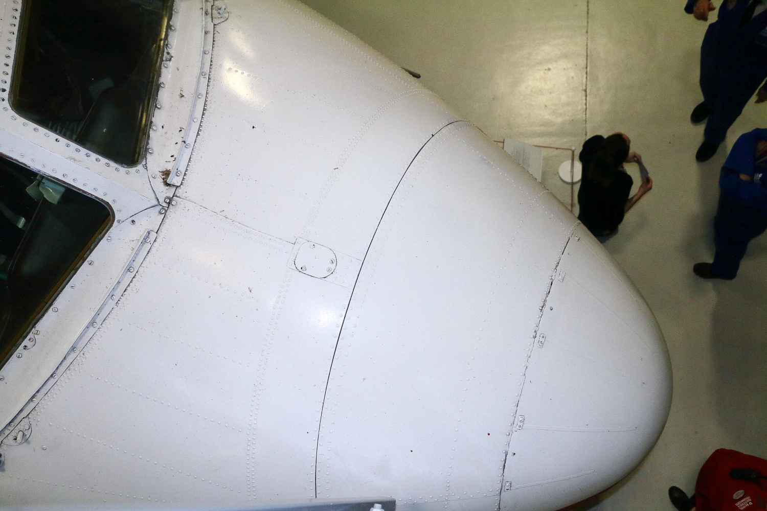
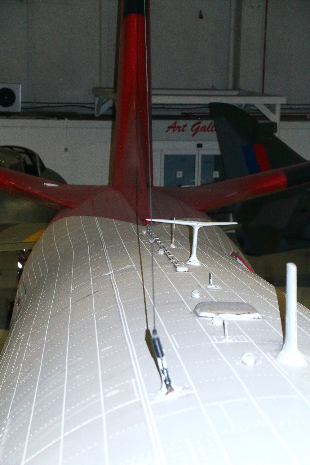
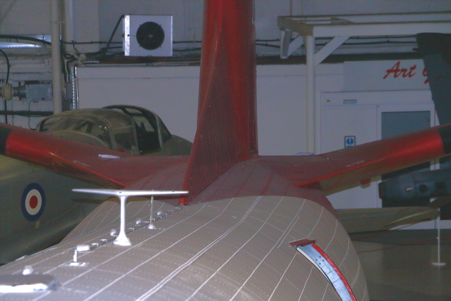
And last few for now - I'll post more when they are relevant to specific stages in the build.
Nose:
Upper fuselage (as clear as I could get in very poor light):
And that tailplane/fuselage interface - captured a few days earlier - with sunlight from the overhead skylights:
So, continuing the build...
Iain
-
1
-
 1
1
-
-
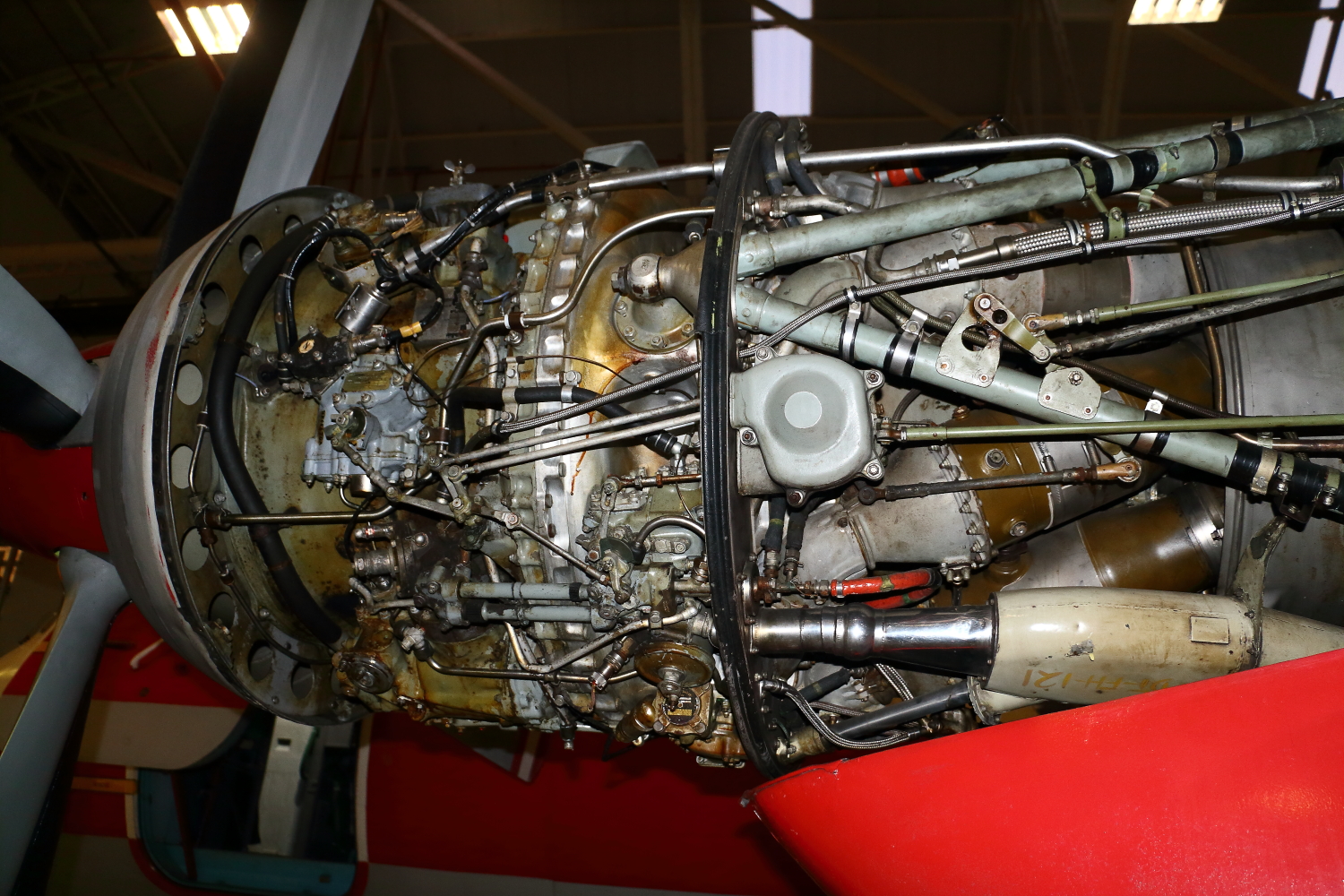
Some more...
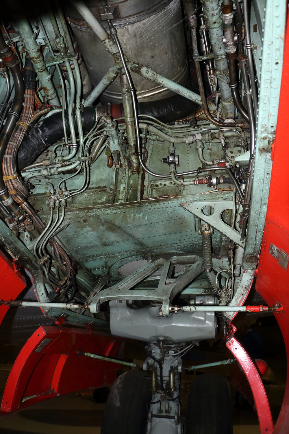
Port engine:
Starboard engine:
Port main undercarriage bay:
Nosegear bay:
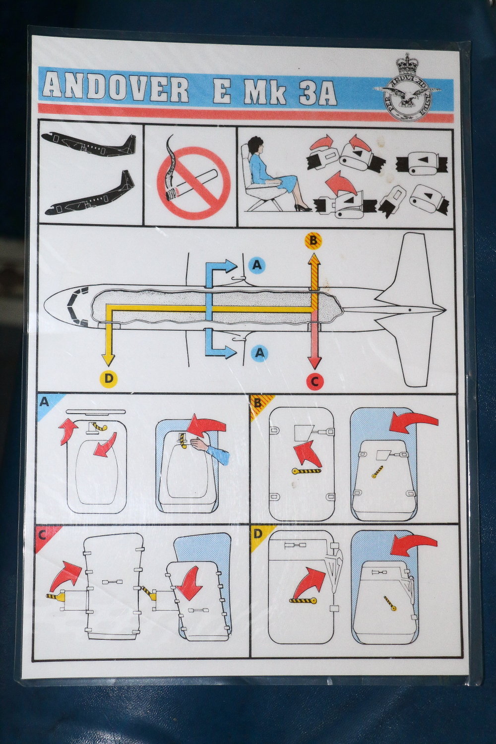
Passenger emergencies card - I have both sides so that I can replicate in 1:32
And for those sitting at their desks reading this, the Emergency Exits...
Are here,
Here,
And here.
🤣
Iain
-
2
-
1
-
-
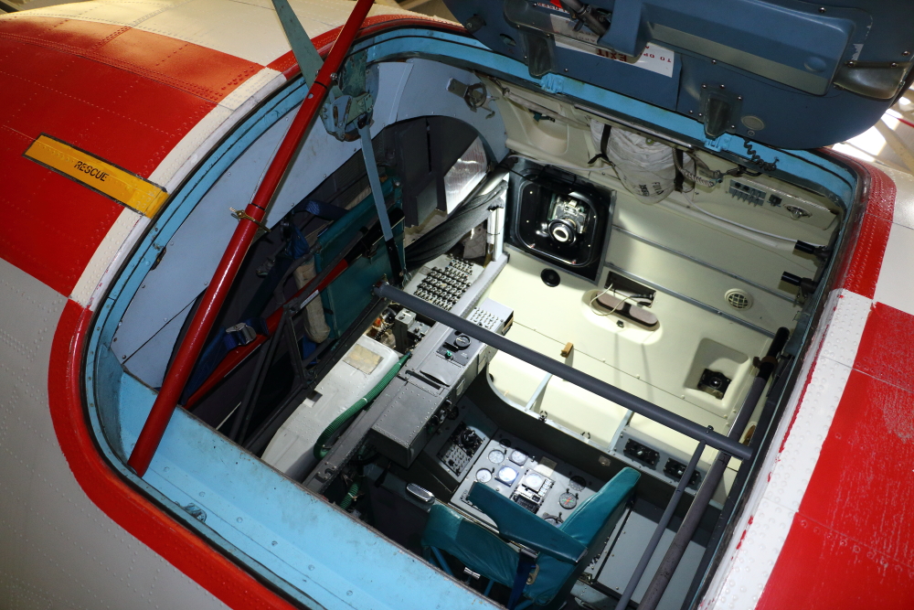
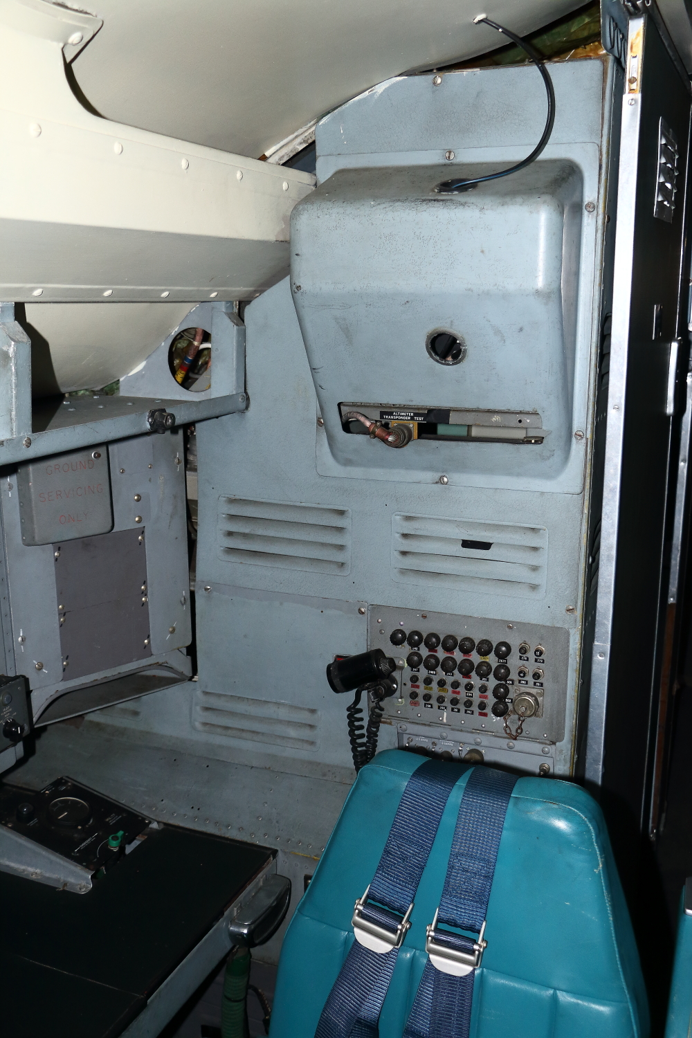
And a few of the photos from the members' Evening - as smaller images - but will give a taste of how useful last weeks' photos will be to the build...
Cockpit:
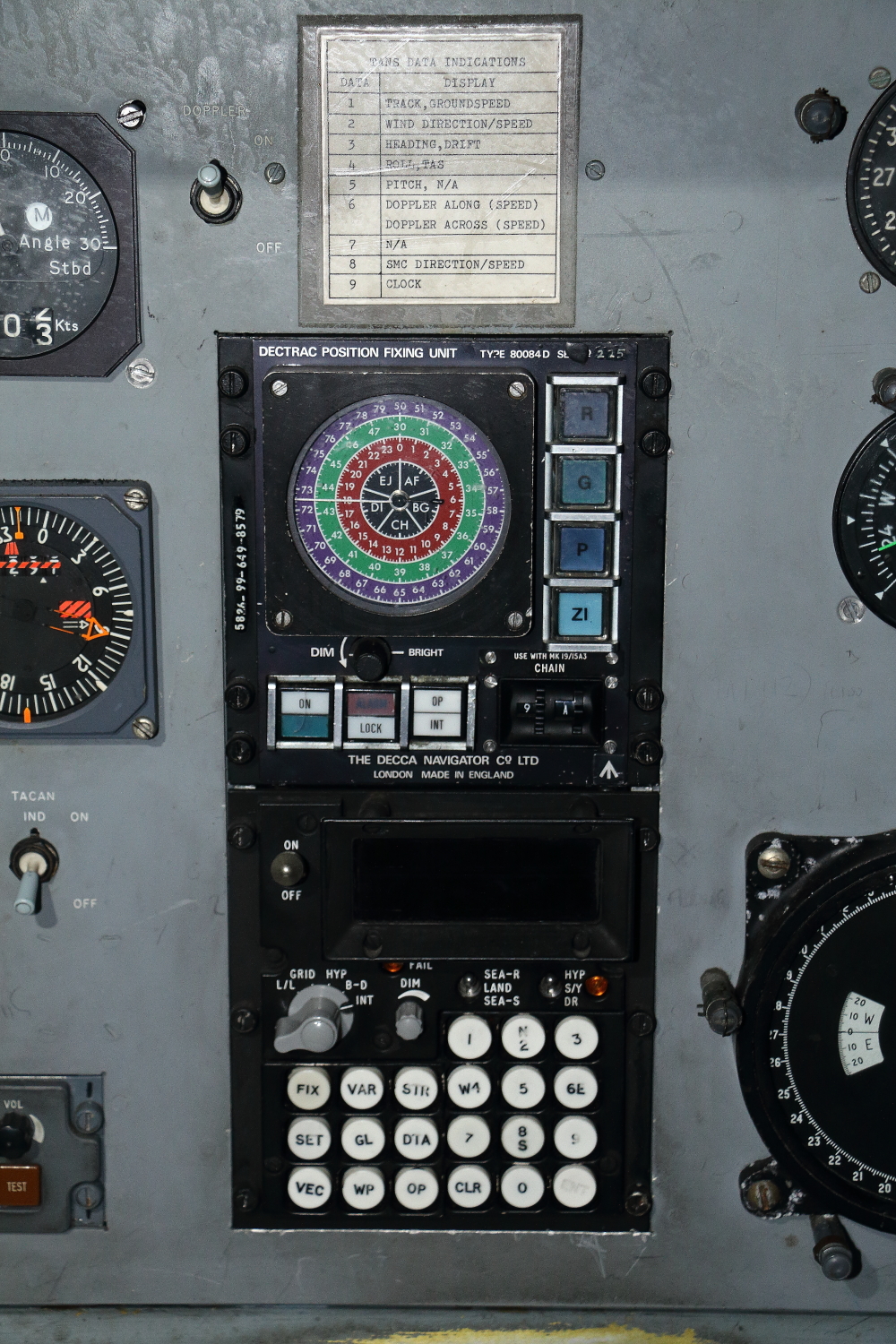
Navigators/Flight Engineers Stations (layout unique to the E3A variant):
Galley:
Rear door - port-side - with para-drop lights:
Emergency door opposite:
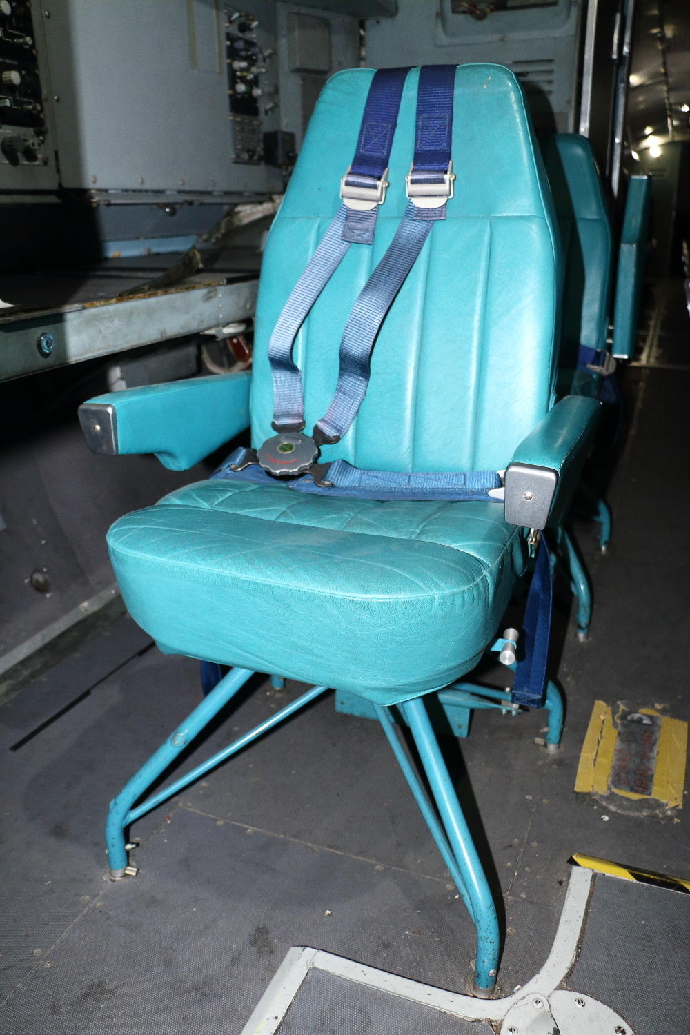
General cabin view looking aft - pax seats fitted:
Back in a mo...
Iain
-
1
-
1
-
-
Then, fast forward to a couple of weeks ago...
Just before lock-down I contacted the RAF Cosford site of the RAF Museum to ask if I could access the Andover E3 they had on display - specifically the interior.
A polite email came back saying that, unfortunately, this wasn't possible - but they offered to take photos of specific areas I required. Lock-down came and with everything else going on I got sidetracked.
Then, two weeks ago - son Cameron is on holiday from school, so I suggested a 'boy's day out' up to Cosford to see what shots I could get of the Andover - without crossing the barrier.
I took a few hundred images - mostly of the Andover - but came away frustrated that there, in a museum, was a surviving airframe that held all the gaps in my research for the project, yet I couldn't get underneath/inside.
Get home - happened to be on Facebook, and saw a 'share' on the HS-748 Group of an RAF Museum 'Members' event the following Sunday - with 'over-the-barrier' and cockpit access to the Andover!!!
Pity the staff I talked to on the Wednesday didn't mention/know about the event - and I didn't see anything advertising it!?
Maybe, just maybe, some planets were in alignment...
Iain
-
3
-
-
The new tool worked better than I'd hoped!
The foil is pretty thin - which is excellent, but it can twist and flex - so I applied pressure down onto the blade - using the printed floor as the cutting guide:
And this happened - exactly what I was after.
It's even separated the rudder pedal assemblies!
The internal sections can now be surface prepped and detailed prior to re-assembly to the floor - with some components moved to suit the E3A version I'm building...
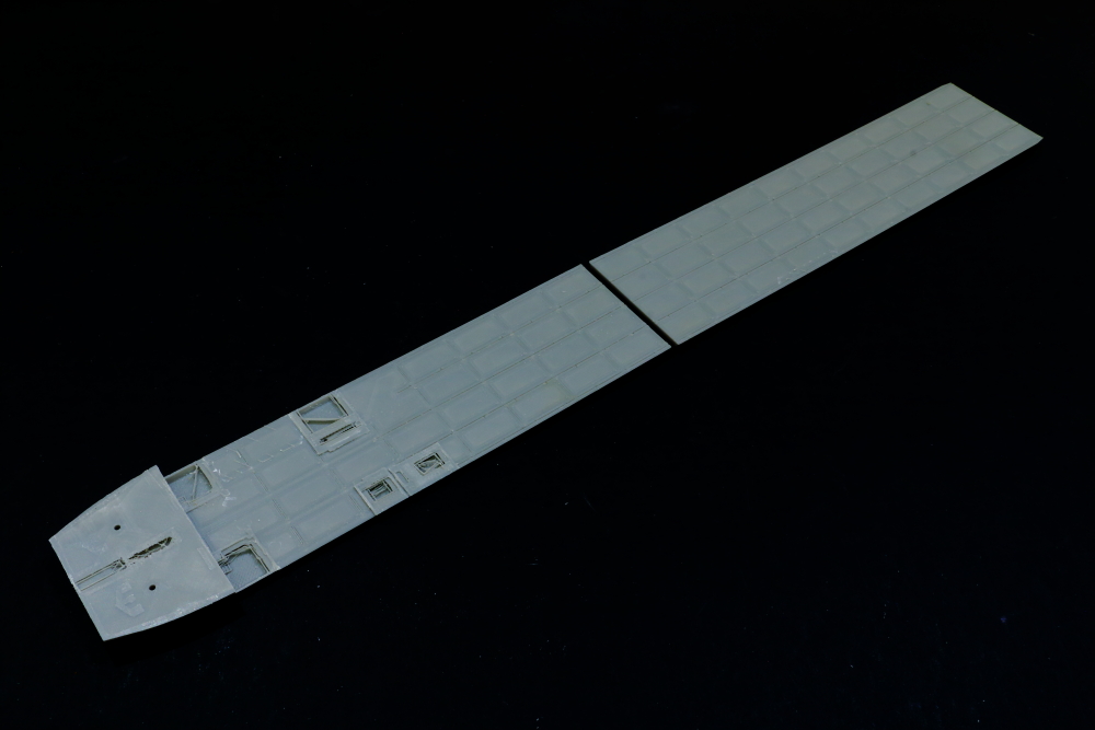
The floor sections will have their surfaces sanded back - to be re-skinned with styrene sheet and surface detail.
With the two main sections of floor there's quite an area to work with!
Iain
-
5
-
-
Thinking through the main interior parts...
Toshihiko has done a brilliant job of re-creating the internal features of the Andover, but there are a few things I want to change, as well as wanting to clean up the print layer lines as neatly, and squarely, as possible.
After several good coats of 'looking at' I'd come to the conclusion that the easiest route will be to remove the vertical sections from the basic floor - which will be re-skinned itself...
The question was how could I do this as neatly as possible - with neat, thin, cuts that would be square and flush with the floor sections as printed.
Eureka moment when I came across these on Amazon: a Japanese Flush Cut Trim Hand Saw which, I think, should do the job nicely - and I can start on building up the interior.
I love finding new tools!
Iain
-
4
-
-
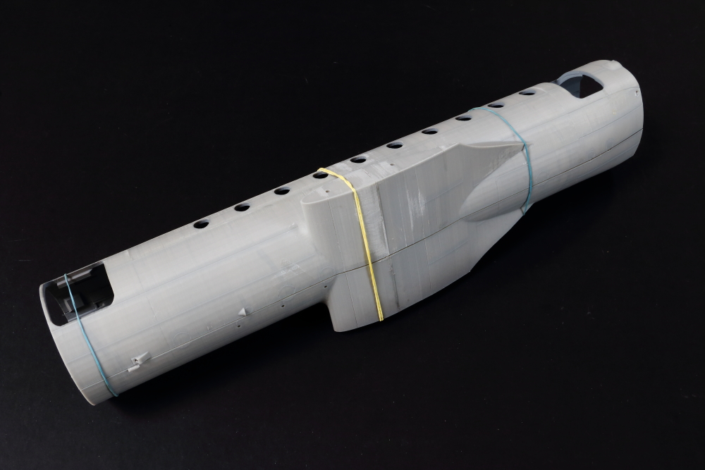
Just to add - and I can't stress this enough - it's hugely important to ensure that everything is assembled square and true - 3D prints can warp a little after printing, especially large parts with relatively thin shells.
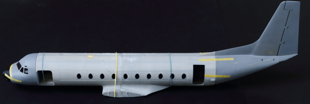
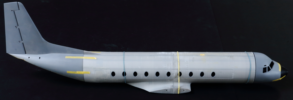
With the main front/rear fuselage sections bonded together it was time, today, to check that the two halves fitted together squarely - with a smooth/straight surface along the fuselage:
And, with that, another test fit of nose and tail - this is going to look pretty impressive when assembled, I think - just wish I could work faster!
Iain
-
5
-
-
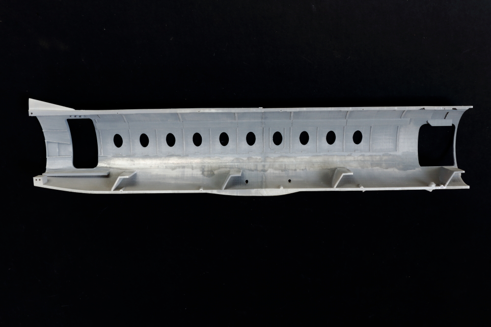
After a week we had this: all square - perfectly aligned front rear on the outer surfaces - with a slight step underneath.
The step underneath is easy to clear - the important sections were upper wing roots/window areas/upper fuselage surfaces:
On the inside I've started to clean up some of the printed in detail - including an upper strip that aligns the top of the fuselage floor that I've decided to remove as part of the clean-up process, before I start any detailing...
Another step forward...
Iain
-
3
-
-
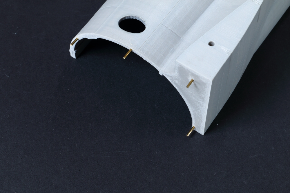
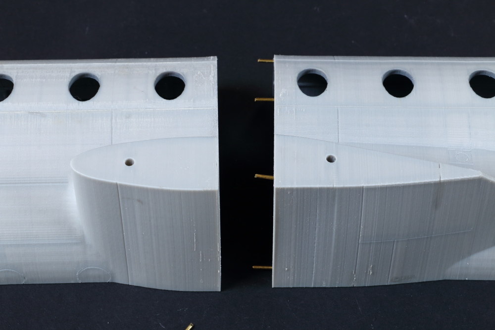
Fuselage progress - joining front/rear main fuselage shells.
I had some 1.2mm diameter brass rod to hand - close enough to the alignment holes in the printed parts - but these needed clearing through carefully with a drill bit in a pin vise.
These are cut to suitable lengths with a suitable side cutter and placed in situ:
There was a tiny amount of adjustment needed to ensure the fuselage sides - and the areas to be glazed - were perfectly aligned.
Sections were bonded on their mating faces with Plastic Weld, before carefully clamping in perfect alignment with G-clamps and spring clamps.
Then left for a week for everything to harden off...
Iain
-
3
-
-
Upper surfaces of the joined inner and outer wing sections - leading edges filled with casting resin and brass rod:
And undersides. Casting resin has been used to fill and stabilise the area where the 3D printed cowlings/nacelles have been removed. This is essential if we are to preserve some strength in the wings - especially as some of this area will be cut back to form the wheel wells:
Here you can see casting resin used as a filler on some holes/joints. Ignore hatched area - I thought that needed removing, but doesn't...
Note the numbered, and colour-coded port.starboard, flap actuator covers - these will be removed and bagged whilst I square everything off and box in the upper flap areas with styrene sheet.
Iain
-
3
-
-
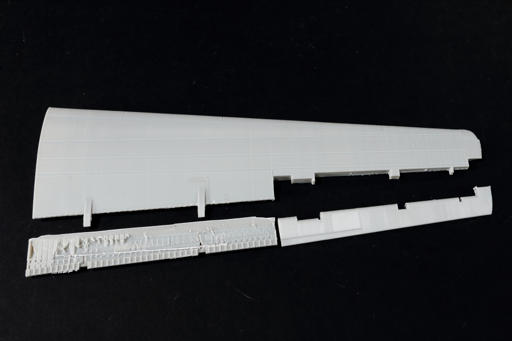
Back to the wing...
Port wing sections as provided by One Man Model:
Starboard inner section that I started modifying previously - here I've removed the upper rear section of the flaps:
Starboard wing outer section - aileron and flap removed carefully with a sharp scalpel and placed back in situ:
And removed:
And underneath view - when you think you've cut through everything needed to remove the section - you find there's more inner webbing from the print process.
Care and patience required!
I've also now done the same with the Port wing.
Iain
-
2
-
-
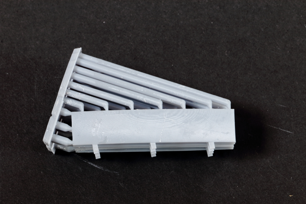
Some more images of the LACI parts.
Lower nacelles - now a single component - and with the revised profile on the front section.
New part top, 748 below:
Main cowling (closed version - 780 top, 748 below):
Note larger diameter at the front (780 left, 748 right):
Undercarriage doors:
And some prop blades - to go with some really nice HS780 spinners (prop units are different to the 748 - in shape and size):
Shapes all look very good!
Ladislav also tweaked the shape of his parts to match the One Man Model wing more accurately.
Iain
-
4
-
-
Then another parcel arrived from Ladislav @ LACI - and, one word - WOW!!
Here's what he sent me - all parts re-done to accurately represent the engines and cowls - as well as an accurate set of props and spinners - for the HS-780 Andover C.Mk 1 and E.Mk.3/3A.
I was really quite amazed.
Ladislav was mortified that we wanted to use the 748 engines as the basis for the larger and modified Dart cowlings/nacelles on the HS 780 Andover C.Mk.1 and E.Mk.3 - and immediately said he was off to create new designs.
And here are the results - and I'm hugely impressed with Ladislav's customer service. I was more than happy to take the 748 parts as a basis for modification - and accept they were blown up from the 1:144 designs. But here we have a full set for the 780 - with correct shapes - and with panel lines refined for the larger scale.
This ticks off one of the big boxes of things I wanted to deal with on the One Man Model kit - and it saves an awful lot of work!
A quick snap showing the rear cowl/nacelle differences - 748 at left, 780 at right.
If you haven't seen the LACI range of 3D printed detailed accessories, take a look here. Quality products!
Back soon...
Iain
-
5
-
-
Looking at orientation on wing - thrust line, alignment in vertical plane from the front etc. - again - these are prototype HS-748 units, not the ones that will be used.
Some tweaks needed - but given the parts weren't designed for this model, or scale - actually pretty good!
And a final 'overview'...
Iain
-
5
-
-
The leading edge pieces of the starboard wing inner section have been bonded to the main/rear section - using Plastic Weld cement liberally flooded into the joints:
You'll probably notice something else...
If you look at the rear of the opening where the upper cowling has been removed, the printed in flaps have gone:
The trailing edge on the flaps - and ailerons - is quite thick - and the strengtheners are the wrong shape - so I'd decided a while back that I'll draw up new flaps and print them.
This meant removing the printed-in sections, before we can start on building up and strengthening the inner wing sections again:
Next stage will be to 'box in' the section where the flap section has been removed.
But, in the mean-time - a quick test positioning of the LACI nacelle parts (note - these are the HS-748 versions - I'll cover the correct HS-780 set a little later) on the inner wing before the latest progress.
Width looks spot on compared to the One Man Model parts - but some tweaks were needed to the fit of the LACI parts to the wing cross section:
Blue skies...
Iain
-
3
-
-
Apologies - just spotted I haven't updated this thread - and there's been progress...
BiG news since last update was that Ladislav Hančar of LACI models has created some superb engines and cowlings for the HS-748 and HS-780 in 1:32 for the One Man Model 'kits' - and I now have a set of each. I'll come back to those shortly.
What I did need to work out was how to fit these parts on the One Man Model wing.
So, 'Operation Dart' began...
This wasn't simple - as the One Man Model parts have the nacelles/cowlings printed contiguously with the inner wing sections - front and rear each side.
So, out with the razor saw - and some careful cutting:
Which gave us this - surfaces where cuts have been made need dressing off - that will come after some important stabilising work - more on that shortly.
Leaving four components to make up the Port inner wing section.
Disappointingly on my inner wing prints there is no internal 'fill', or structure, from the print process. Even before modification, you could squeeze the upper and lower surfaces of the inner wing section together - and they would 'give'. Even looking at the parts when they first arrived, you could see the upper and lower surfaces 'bowing' out'. Cutting up these parts confirmed the interior is completely hollow - disappointing as a fill is easy to add at the print slicing stage and would have helped a lot with strength - but we have a 'plan' that I'll come back to...
Iain
-
3
-
-
On 1/23/2023 at 11:40 AM, keith in the uk said:
Over to you chaps as the Clash once sang Should i stay or should i go ?
You should Build!
Iain
-
OK - who mentioned Trumpeter Lightnings?
Yes - I got really burned out on the project - but it's not completely dead and the patterns have been out over the last month for a coat of looking at.
I'm doing the Norwegian Blue variants...
Iain
-
2
-
 2
2
-
-
A Mk.III would be nice.
But - I'd buy just 1.
A later mark - and I'd buy quite a few...
I guess, to most of their audience, a Meteor is a Meteor - and a wartime 'companion' to their 262 to boot.
We'll see what we see I guess - it'll be yet another new release in my go to scale - so what's not to like?
Iain
-
2
-


1/48, 1/72 & 1/32 - Hawker Siddeley HS.748 & HS.780 Andover by One Man Model (3D printed models) - HS.748 & HS.780 Andover C.1 released
in The Rumourmonger
Posted
Building the 1:32 HS.780 Andover at the moment - with the LACI nacelles/engines/props - and really enjoying it!")
Iain