

Stickframe
-
Posts
627 -
Joined
-
Last visited
Content Type
Events
Profiles
Forums
Media Demo
Everything posted by Stickframe
-
International 5000 Paystar 6x6 1/25
Stickframe replied to Stickframe's topic in Work In Progress - Vehicles
Hello model builders, thanks Yes, as Trevor, said, "two steps forward, one back"....right. And, Andy, good eye! the resin rims are indeed two part, and because the tandems connect, only the inner halves are shown for now. As I've explored this problem I've come to wonder if the "levitating"/"anti gravity" tire/tyre situation might be exaggerated because of a loose fit for now. I'm adding some backing between the wheel hub and wheel to see if that helps. And, if it doesn't, well, maybe a custom base is in order 😄 OK, thanks for having a look - Cheers Nick -
International 5000 Paystar 6x6 1/25
Stickframe replied to Stickframe's topic in Work In Progress - Vehicles
Hello gents, and thanks for taking some time to leave your comments! I appreciate them! Especially, as the headaches mount 😲😄 So, the upside of scratch building: it's a challenge, requires some research, allows you to build some non-kitted projects, requires the builder to consider how to best represent whatever it is - good fun! The downside, well, shoot - sometime a guy might build what he thinks he sees, rather than what he actually sees.....sometimes, the "eyecrometer" needs adjusting, and sometime, for the sake of laziness, a guy might just go ahead and use some kit parts because they look to be close enough.....even though, there appears to be a problem from the outset 🤦♂️more on this below. But, in the meantime, I went about making up the bed: So this is coming right along, and almost done - I need to add some D rings to the bed, and a few odds and ends, then on to other parts. Looking pretty good - no problems at all! 😀 Oh what a treat! so much model building goodness! but, - uhh, wait a minute.....is that?? is that rear end still floating!???? what the?? I have torn apart and rebuilt that at least twice already! what the??? Hmmm - I guess I'll need to figure out what's wrong now. This is what I referred to above. At the outset, I was concerned that the kit's walking beam suspension parts did not look right, and I keep getting proven right - hooray for me. First time through, these wheels, inside and outside were floating about an 1/8" above the ground....and now, well, only the inside part is floating. Early on I pondered just making up my own walking beam and brackets, specifically because when you do that, you can keep the central pivot point moveable, which results in a self-levelling suspension, which in turn, lets wheels and tires/tyres to seek the ground independently - which translated means that all four sets of tires and wheels usually touch the ground as planned. 🧐 Not sure what I'll do about this. The good news is the bed and tires/wheels are not attached, so it's easy to reach this area. But, well, what to do next? I used brass axle shafts, so I could bend it upward, but, that might just raise the outside tire, and make both float.....again. I guess I'll futz around for this when I'm done with the bed. While the purpose of this picture was to show the ramp, and tilting extensions, I realize now it also proudly illustrates my floating wheel! 🤦♂️ At this point, I think I'll get back to the bed later - and will instead fool around with the suspension and try and resolve the floating tires, without destroying something else! Cheers Nick -
US 1/4 Ton G503 utility - Willys Jeep
Stickframe replied to Keeff's topic in Ready for Inspection - Armour
HI Keith - what a build! she looks great - really nice finishes all around Cheers Nick -
1/25 scale well used all terrain drill rig
Stickframe replied to Stickframe's topic in Ready For Inspection - Vehicles
Hi model builders, Thanks and glad you like this somewhat/totally out of the ordinary project! 😃 I really enjoy taking a shot at weathering, but how often do you need to show this much weathering? not that often, so have fun when you can! This project was indeed fun - both the build and the finish. Almost makes me want to try another piece of industrial equipment! This project came together fairly quickly, but it took a lot of work - I need to get re-motivated and keep going on the truck that will haul it! Cheers Nick -
Rough road Afghanistan 1/35 dio civil works
Stickframe replied to Stickframe's topic in Ready For Inspection - Dioramas
@Clashcityrocker, thanks, Nigel @Keeff, thanks, Keith. This project evolved over time. The original idea had different vehicles and buildings in mind, but as I did more research, and spoke with some directly familiar with what was happening, the overall direction changed, and here we are. I thought the variety of events, people, places and vehicles became very interesting - a fun project. @Alpha Delta 210, thanks! glad to know that you were able to see the various bits and pieces! @bootneck, hi Mike, thanks very much! As for the build, sure, and I appreciate your comments and questions. I enjoy trying to get results that are not toylike too! It drives me crazy to put time and effort into something with results that are fine, but clearly look like models in photos and not the real thing! As a general observation, I find taking photos of the final build outdoors goes a long way in achieving the desired effect. This can be a double edged sword, as good things look good - and less good things look a lot less good! But with some practice, they get better. Regarding my friend Romain's input, that is a longer story. I post on another site too, and he was a regular, and offered comments on several projects. Going beyond the more obvious, like craftsmanship, his bigger critique had more to do with intent, and building/painting/organizing parts/objects in a way that reflect what they actually look like, rather than what I might think they look like. That is, paying close attention to the details in photos, and if need be, for figures, taking a minute to try and physically replicate what you are trying to make a tiny resin guy do! I think this picture sums this up: Obviously, this is a very close picture, so good and bad shows up 😄 but, I think it illustrates the point - Romain painted this guy and the cat he is petting, and even years later I marvel - this guy even looks good in 1/35 scale. Regarding the dio itself. I enjoy looking up context images and trying to identify the attributes that make up a place. I don't consider this to be the dio equivalent of "rivet counting", and instead aim more for trying to capture the character of a place. So, I search for lots of photos of the place I am trying to make, like in this compilation: After you look at many images, you begin to see patterns, colors and textures that look "right" or "wrong" for what you are trying to build - I suppose maybe it is the equivalent of "rivet counting" 😄 But, as I'm not an architectural, cultural, or military historian, I only take this so far, but far enough to have some elements/textures/colors that I want to try and capture/represent. I enjoy making the buildings and landscape - and usually use a pretty low tech approach. The base is wood frame with a thin plywood sheet, and is 30" (76 cm) x 18" (45 cm). For this project I used rigid insulating foam for the building and base. This is an interesting product, as it is soft enough to allow you to easily emboss with patterns, like stone, brick, and textures, yet tough enough to require some very messy work when carving and scraping to make landforms. I use a product called "lightweight spackle compound" for filling in gaps - you can see it above, as it is white. You can find this in hardware stores, as it is intended to be used to fill cracks in walls, and is cheap! The ground plane is coated with several layers of different densities of "pumice gel" - which is something you can find in art stores. This material is not cheap, but the results are pretty nice. It took me a while to develop a technique for applying this stuff, which I suppose feels more or less like sticky sand. I tend to use the medium and coarse textures. There is a fine texture, but it is really fine, and hard to see when applied. The medium and coarse have enough texture to leave shadows, which I think goes a long way toward making a convincing ground plane. For paint, I sprayed the building and ground plane with a base coat of Vallejo IDF Sand primer, followed by layers of complimentary earth tones. Then, added various washes to punch out details - like the colors and gaps between stones on the walls etc. Figures....another story - They challenge me too. I give each figure a primer coat - either Vallejo IDF Sand or Tamiya grey, then paint the rest by hand (acrylics), using Vallejo Model Air colors for basic colors (clothing, uniforms, weapons etc) and Scale75 paints for skin colors and tones. As is often said, practice goes a long way toward getting this down. I figured out that painting in faint layers, and gradually building colors up helps too - oh, and did I say, practice helps? I does!! I also give the figures various washes. In this case, bodies received dust coats, and skin, various shades of darker colors in order to try and define eye sockets, noses, and ears with shadows. Romain though, used enamels and oils! the results are very crisp and convincing 😲 And here you can see - Romain's guys on the top row, and mine on the lower row. A key difference you can see between our figures is that Romain achieved depth and interest in each, whereas I seem to get the effect sometimes, but not on each, which was not intentional! It turned out that we independently chose different uniform colors, BDUs (battle dress uniforms), and ACUs (Army combat uniforms) - which as it also turns out, is just fine, as in this era, both were being used, and it adds some variety to the scene. Summing up, look at plenty of reference images, practice, and select an approach that you like and can duplicate - and keep after it 🧐😃 @raider of the lost part, thanks! I'm a strong advocate for outdoor pictures, to the point that I look forward to taking pictures of the final projects 😃 Regarding the sheepsfoot rollers: My original idea was to use a wheel loader, as I converted a 1/32 scale toy to an armored unit, which looked pretty good - BUT - it looked HUGE - standing alone it was fine, but next to 1/35 scale figures and vehicles, well - not so good. I think this picture might have given me the idea to scratch build the roller! And, yes, these rollers are commonly used to compact graded and filled surfaces, roads and pads. @Pete in Lincs, thanks, Pete. I enjoy researching projects, and this was no exception. By good fortune I was in touch with a fellow who was doing this work in this setting, so was able to try elevate some authenticity in the project. Thanks for having a look - Cheers Nick -
Hello dio builders, This is a project I built ten years ago. It includes a scratch built sheepsfoot roller, a heavily kitbashed M1083 to represent an armored dump, a detailed MATV, several figures, and of course the dio, which is intended to represent a rural Afghan village. The idea came because I had an acquaintance who was an engineer serving in Afghanistan in the early to mid 2000's, where he operated heavy equipment, and provided plenty of insight and help. This project holds sentimental value for me, as a fellow model builder (Romain Baulesch), who was truly a master model builder, who contributed some figures to the effort and provided greatly appreciated critique along the way. He has since passed, which is a loss for everyone who knew him. While I treasure the figures he sent, I value his friendship, mentorship, and patience even more. He was quite direct with comments and criticism - but with the obvious intent of helping us to improve - someone I greatly appreciate having had the privilege to have known. When I finished the project I was pleased with the build, but the photos were awful - that is, the pictures were fine, but, I like taking outdoor pictures of the finished build, but, as I live in an urban area, it is difficult to get images without visually overpowering backgrounds. Within the last few years, I have figured out how to crop out the unwanted background images (ie vastly out of scale everything), and how to impose what I want of the photo over a context appropriate image. This is a lot less high tech than it may sound, but, I like the results. Happily, I still have my original photos, so didn't need to to take the project out for new photos, which was good, as it was cold and rainy today! Ok, on we go: The idea behind the dio is an engineering team in a rural village working on the roads, along with locals offering their thoughts on all of it - the two guys not dressed in BDUs/ACUs or local clothing could be contract engineers. Well gents, this was fun to take some time to revisit, and I hope you enjoy seeing it, and thanks for having a look - Cheers, Nick
- 10 replies
-
- 24
-

-

-
1/25 scale well used all terrain drill rig
Stickframe replied to Stickframe's topic in Ready For Inspection - Vehicles
HI model builders @Alpha Delta 210, @keefr22, @Keeff, @Davi, and @Pig of the Week, Thanks very much. For whatever reason, I didn't anticipate this project being as fun to build as it turned out to be. I've built a few pieces of construction equipment before, but have not built up something like this. The tires are from an old 1/32 scale monster truck! Axles, driveline, and engine are 1/35 scale extras, and lots of evergreen styrene. The weathering is 90% acrylics - both painted directly onto parts and heavily diluted to make washes. There is some pigment used to look like dirt, and some lacquer based grime colors used on the engine and all around the main drilling mechanism. Thanks for having a look and for leaving some comments - Cheers Nick -
Hello model builders, This project will eventually become the load on the bed of a project I'm currently building, an International Paystar 6x6. But, as I started this first, I decided to paint it up first, and then take it out for some photos - a couple of process photos to start: Up first some Tamiya Fine Grey primer, followed by some art store ugly green. I then dusted it via airbrush with some Vallejo US Interior Green: And am ample about of wear and abuse - I haven't had a reason to do any heavy weathering in a while, so I caught up on that right here! This projects intended to be clearly secondary to the truck that will eventually be hauling it, but it turned out to be a lot of fun to build, and I'm really pleased with the results. It will eventually be back to this section, but as the load of an equally decrepit truck - thanks for having a look - Cheers Nick
- 18 replies
-
- 29
-
-
International 5000 Paystar 6x6 1/25
Stickframe replied to Stickframe's topic in Work In Progress - Vehicles
Hello gents, I'm pleased to report, the beastly truck is far enough along that you can actually see what it is suppose to be - a big and grubby rig at that! Ah! another majestic beauty well under way! 😄 oh yeah, what a treat! 😁 As you can see, a variety of new parts built and installed - the driveline, winch and rack, chassis extension and bumper up front and lost of small stuff - perfect! Except: 1) as predicted, the kit provided rear walking beams are not level. Which, as you can see above, means that the front tire, on the right side of the rear tandem is happily gravitating above the proverbial pavement; and. 2) with zeal, I made the chassis too long - nice. Not way too long, but about an inch and a half too long - as is, this looks like a bed truck - just begging for some gin poles - but, that's not the destiny of this project. I spotted the problem with the walking beam early on, but just having bult several of these, I had no desire to do it again - clearly, I should have. To fix this, I am not going to rebuild the rear end, and will instead force an object between the beam and the bracket, forcing them apart, and downward - this will not be a graceful repair. As for the chassis, out will come the saw, and two sections of frame rail. While I am annoyed with the blunders, I do like the look - the opposite of graceful, aerodynamic, or attractive! I'm looking forward to paint and weather on this beast! Looking at my prototype pics, I found all sorts of interesting things to make, like the transfer case supports, which feature some novel barnyard bracketry to support it - looking very much like 1/2" steel, bolted to the sides of the housing and frame. And a variety of odds and ends added to the motor. Plus, some body mounts (next to the radiator on the frame rail). The kit would have you essentially float the fenders and radiator cowl directly over the radiator, and rely on two small pins to hold it all together. I could not abide that. Right after I took these photos, I cut up the frame and tickety boo - it was done: Simple! 😃 and now, just glue it back together! Perfect! 😁😁 Thanks for having a look - Cheers Nick -
International 5000 Paystar 6x6 1/25
Stickframe replied to Stickframe's topic in Work In Progress - Vehicles
@JeroenS, hi Jeroen, thanks - getting any model to look convincing is the challenge! I don't want these to look like toys 😁 be it a kit or something like the drill rig. It's funny how sometimes it works just fine, and others, well they wind up in the back of the pile - @raider of the lost part, hi Raider - you know, I haven't run into warping, but usually have to address flexing - which drives me crazy! I don't want to worry about picking a model up to move it! To address this I usually add a full length strip of .040" styrene to the inside of the frame wails, then add various sheet material to make the new part look like a channel from the outside. Next, I add various frame stiffeners to the inside. I only have one on this so far, but more will be added - one to support the transfer case, and the other at a mid point - @keefr22 - yes, we luddites! I started my real job right at the transition from pens and drawing, to autocad - I was trained on the pen side, so never learned to use cad. It's funny, I didn't want to learn it as I was just getting good with a pen! And happily I was able to ascend the ranks during a time when that was ok - as I became a team leader, I could establish concepts, that hotshot designers would work up in cad! As a consultant I do the same. I draw things up, and send jpegs off to someone I work with who is a CAD ace and she cranks them out! And now, just hobby knives, files and drill bits! OK, on we go - spent some time refining the front end - detailing the leaf packs, making up brackets, and adding steering. Coincidentally, a few of these steps were similar to those on the big red KW: One other tool I own is a 1.3mm nut driver - let me say, if you decide to use these tiny nuts and bolts, it makes the process a lot easier! You can see a nice mix of metals, styrene, resin, nuts/bolts and rivets, which equates to slow going! I'll sand/file/clean up the control arms on the hubs. There is a lot going on here - there is a 1/16" dia brass rod used to hold the hub to the axle, then the control arms, CA'd and pinned in place on the hub, but, as you can see above, in these merciless, giant clear photos - the results are a bit sloppy - 🤦♂️The good news is that these connections will be out of view, as the hub is slightly inset in the back side of the wheel. And for fun, a scale comparison with the red KW: This build looks pretty small, but it's actually quite big! OK, thanks for having a look and happy model building - Cheers Nick -
Kenworth 963 Super 1/24 scale
Stickframe replied to Stickframe's topic in Ready For Inspection - Vehicles
HI @AV O, thanks, but no apologies needed. I understand - and again, appreciate you taking a look to begin with 😃 I probably should have spelled out the two units of measure to begin with - like tire and tyres, hoods and bonnets, or grey and gray 😄 Cheers, Nick -
International 5000 Paystar 6x6 1/25
Stickframe replied to Stickframe's topic in Work In Progress - Vehicles
HI Pete, I'm glad it's beginning to pass the eye test! As I was very curious about whether I could get the suspension to work out, I went ahead and soldiered through my front leaf packs, and temporarily attached the front axle - I needed to know 😥! Ahh - feel better now! You can see the dilemma I was wrestling with - did I get the axle centerlines to match? and happily, yes, sitting level! And a close up - clearly a dry fit! but, the bottom line is it is close! And thanks, the rig is taking on a stout look. Clearly there is more to go, but it's a lot easier to do when the basic layout is right. Thanks for having a look - Cheers Nick -
Kenworth 963 Super 1/24 scale
Stickframe replied to Stickframe's topic in Ready For Inspection - Vehicles
@AV O, well AV O, I am still confused - the note above "6'/2m" is intended to indicate that thee tires are 6 feet/2meters tall. I include both units of measure because I don't know who might read this, and what unit of measure they are familiar with. I did round up from 1.86 m to 2m, but I can live with that. Anyway, thanks for reading it, and dropping by - on we go and happy model building - Cheers Nick -
International 5000 Paystar 6x6 1/25
Stickframe replied to Stickframe's topic in Work In Progress - Vehicles
Hello model builders, @dnl42, well, shoot - I didn't think you guys would be that interested in the scratch work going on in such an odd build - figured I was pushing my luck a bit as it was! That said, I reall appreciate hearing that you guys like this so far. @Pete in Lincs, thanks Pete - yes, the drill rig and the truck will get some indication of use - this will not be a shiny glossy package like the KW! @keefr22, thanks Keith - no, no 3d printing for me. While I think the idea of 3d parts is really cool, I don't have as much enthusiasm for getting into that technology - learning CAD or something similar, then going through what appears to be a fairly intensive effort to get the printing process to work correctly - again, the results are sure nice, but the process is not something I am as interested in dealing with. So, for now, just what I can achieve with a knife, drill, and file! @JohnHaa, thanks Johnhaa, thankfully I have kept all those old sprues and they do pay off from time to time, with some odd little part that looks just right! And as you mention, coupled up with some raw materials, there are lots of opportunities 😀 @Toftdale, thanks, Andy - despite the drill rig having been intended to be something of an extra, it turned into a pretty good project - Speaking of projects, well, I began work on the truck itself. As this is going to be a mix of kit, aftermarket parts, and scratch work, I anticipated some challenges, and they have arrived - some more obvious than others! On the more obvious side of things, getting kit and aftermarket axles and wheels to be friendly with one another: Starting with the rear axles - well, they needed some work. I purchased some KFS tires/tyres and wheels some time ago, with the thought that I could probably use them eventually, and their time has come! Unhappily for me, I did not buy the hubs that went with them - why not??? well - who knows, I didn't. But in order to use them, I need hubs. On to the hubs - this was not particularly hard to address, but it was slow going. I wound up cutting the hubs out of some junk box wheels, then inserting them between/in the resin inner rims, then, added a styrene backer plate, which will be flush with the axle housing, and with a hole to allow a brass axle shaft to be inserted. Once that was done, went about widening the rear axles to match the front axle, and then, to add brake drums. A lot of work for what amounts to what might have been a fairly simple task - "if I just had a 3d printer!" 😄 The kit axles are OK, but as you can see in the top row of pics, for whatever reason a part on the diff left a big gap when installed, so I fixed that which was easy enough - and looking back, I should have appreciated that relative ease a bit more. The purpose behind all of the aforementioned was to get this result - the outer face of the tires front and rear are now flush with one another! I have since added additional sleeves to the axle housings so they now look right, and this pic was taken before I added the drum brakes. The front axle still has a long way to go. It is also from KFS, and a part I have ordered several of - I really like these! And above the formative steps in wedding kit, aftermarket, and scratch parts. At first glance, all of this looked OK, but I had the ominous feeling that something wasn't right. Starting with the front tire place in the fender well. No axle, just placed, and it looked awfully cozy - alas, a bit too cozy - there is no axle in this pic - which takes me to the pic on the lower right. Notice those two subtle red arrows? well - the top of the tires and frame rail sure look close....🧐 in fact, they look too close. Having built a few projects generally similar to this, it became evident that something was not right. In brief, the front axle is not all that low, relative to the frame rails, but it is lower than the stock, solid axle, which means, the rear axles also need to sit lower than they did with kit parts. So, out came the knife and saw, and off came the rear suspension, and as you can see, it was adapted to sit lower on the rails. Then, in the front. Well, looking at prototype pictures it was obvious that the oil pan has a deep sump. This is done so that the front differential doesn't hit it. So, it was cut and adapted as well. I went ahead and made up the rear leaf spring brackets. Naturally, these are different than the kit parts (which I wasn't going to use anyway) but more importantly with some measuring, it becomes obvious that in order match the pad width of the axle leaf mounts, the brackets on the chassis needed to be off-set from the frame rails, which, happily they are. This crude mock up illustrates the axle in the correct horizontal location, which clears the oil plan sump, and with leaf springs will sit below (won't be touching) the rest of the oil pan. So progress is being made. I'll build the leaf packs, then address the front brackets . OK, thanks for having a look - Cheers Nick -
1970 Dodge Coronet Super Bee
Stickframe replied to triumphfan's topic in Ready For Inspection - Vehicles
What a beauty! It looks loud and very fast. Is that the 440 with the six pack carbs? I had a friend who owned a '67 Charger with the 440, built heads, four speed, and ran on chrome steel wheels. He did a lot of street racing with it, and won a lot. I think people underestimated it because, unlike your model, it just didn't look or sound all that fast! Yours tho, clearly looks the part - Cheers Nick -
International 5000 Paystar 6x6 1/25
Stickframe replied to Stickframe's topic in Work In Progress - Vehicles
@keefr22, you know, you raise a very good point - almost to my detriment, I'm not too sentimental about most projects, so when they are done, it's time to find something new! 😀 and to @Pete in Lincs comment - Yes! I enjoy building these, mercifully I don't own a huge stash! I think if I did, I'd just be annoyed looking at boxes of kits that I am no longer too interested in building. That said, I do have a few kits that I should make, as I paid plenty for them, and they are reputed to be pretty nice. But for now, I seem to enjoy tinkering away at the more, shall we say distinctive projects 🙃😄 @raider of the lost part, thanks! And, you will see the Paystar underway shortly. As you will see below, I am about to call the drilling rig done, and it will soon be off to painting, and toward the end of last weeks parts for the truck arrived. I now have the kit, a KFS front axle, more styrene sheets, and some old KFS tires and wheels! So, on we go with the drill rig. My model is based on a composite of images of several of the prototype, with each having some interesting attributes. The relative luxury of scratch building without a specific prototype in mind or working drawings, and instead a handful of pictures, I don't mind taking some artistic license. It also helps that I know practically nothing specific about these rigs or their operation. Rather than seeing that as a hinderance, I see it as the opportunity to build with some relative freedom - as long as what ever I build remains in character and looks convincing 😀 Before some progress images, the following includes images of a few prototypes: As noted above, not exactly an objet d'art! Not in terms of it being a collectible trinket, or as something that is even generally visually appealing! But, as art is in the eye of the beholder, I like that these are complicated and fussy, and ride on giant high flotation off road tires - and of course they are four wheel drive and boast several winches and lots of other cool stuff! Ideal for this project - These little rigs have plenty going on - so, I went about adding what I could - the easy parts are things like the front winch and fairlead, tool boxes, storage decks and so on. The less straight forward parts are all of the various pumps, hydraulics and well, things that I can not clearly identify - but, they are there, and look interesting. I like that you can see the transfer case and driveshafts, suggesting, as this will be on the bed of a truck, they will be evident. There is a control panel in the rear, and a head assembly of some sort that drives the drill bits. Plus several hydraulic lines and on and on. I suppose I have shown about 30% of the various lines, which I can live with! At one point I began trying to chase lines and determine their purpose - and realized it was a bit of a fool's errand. I want something that looks about right, and don't need a replica. I did what I could on the mast. I think I now have a rudimentary understanding of how these work, but I am still confused by exactly how they might work. But, thanks to some photos, I was able to get something that looks credible. I kept the mast moveable in order to help with eventually stringing winches and for painting. This rig provides an abundance of interesting things to workout and build - as to the accuracy of my interpretation of it all, well, beyond looking "about right" and as I had hoped, this is not going to wind up on the desk of the proud executive of the company that actually builds these! I'll add a few more bolt heads, and other odds and ends, but this is soon to be ready for some paint. As I cannot help myself, I'll likely start futzing around with the truck sooner than later! Thanks for having a look - Cheers, Nick- 31 replies
-
- 10
-
-
Your model is looking very good - a few years ago I built the Studio 27 Penske PC4, which I enjoyed. This kit was also lacking engine detail, so like you I added the parts I wanted. As a whole the project went together pretty well, except for the four control arms extending from the monocoque to the rear suspension. The kit only provided brass rod, and the locating points were vague/non-existent, so I scratch built my own and mounting brackets. So, while there were a few challenges, not a bad kit - and it looks like you are well on your way a nice build! Cheers Nick
-
Hello model builders, I have only started this project in a roundabout way, as the kit and various parts and materials I need have not arrived. So, while waiting for parts, and paint to dry etc on another project, I decided to build the load that will eventually reside in the bed of this rig. Before we get into the load, I assembled some pics of the real thing: Ahh, well, I don't think this unit could boast majestic beauty, which is precisely why I chose to build it. It's a heavy 6x6 - you can clearly see the transfer case and drivelines - and the decidedly un-aerodynamic cab - again, perfect! The kit I am waiting for is not a 6x6 so I'll add a front axle and suspension, and as the kit includes a dump bed, I will substitute it with a flat bed, designed for carrying a vehicle - like this: OK then - some stylish good looks! while those rear tires look pretty cool, they almost look too cool - I'll be using skinny mud doubles on mine. As for the bed, this is just a photo manipulation a picture of a bed overlayed on the truck and chassis only, but it illustrates what I want to build. And what will go on the bed? This: And what is that you ask? A suitably unattractive, dare I say ugly, load for this brute - an all terrain drill rig. As it was so, uh, unattractive, I added a sloping hood - I just couldn't stand it as it was. I had diluted myself into thinking this would be an easy, quick build. Well, that was not a valid conclusion. It's turned into quite a project. I decided this would be fairly easy to build simply because it is ancillary to the primary project, something to bang out while waiting for the kit to arrive - 😄 So, this is a junk box special - the tires and inner wheels are 1/32 scale, the inner and outer wheel hubs, axle, engine and many other parts are 1/35 scale, while the seat and steering wheel are 1/25, with the overall intent of making a convincing 1/25 vehicle. Plenty of styrene too. I know nothing about these rigs in real life, and am relying on pictures to estimate what's going on - I now know this has at least four winches, numerous hydraulic pumps and lines, and plenty of one-off build assemblies. It has become a project in and of itself. The long range plan for this and the truck is to subject them to heavy weathering, rust, and grime, making a rugged and ugly duo! Thanks for having a look - Cheers Nick
- 31 replies
-
- 10
-
-
Kenworth 963 Super 1/24 scale
Stickframe replied to Stickframe's topic in Ready For Inspection - Vehicles
@JeroenS, Hi Jeroen, thanks very much! I'm glad you like this project - Our early conversation is what led to it 😀 @raider of the lost part, thanks, Raider, I appreciate it @Ryedale Wolf, thanks, I agree, this is indeed a different build - and a fun challenge. @AV O, well AV O, yes, I am sure, these tires are quite tall: I did use some exaggeration and rounding - the tires are indeed 1.86m in diameter (6.11'). The resin tires used in the model are just under 3" in diameter. I realize these are not the tallest tires in use, take a look at the tires used on mining haul trucks, or those used on this trailer: Cheers and happy model building, Nick -
Kenworth 963 Super 1/24 scale
Stickframe replied to Stickframe's topic in Ready For Inspection - Vehicles
@dnl42, thanks very much. Considering how big (long and heavy) and awkward to hold this is, I really enjoyed building it. It's too bad that it's done! I would have liked to keep going, as opposed to at least one other project I have which has been patiently waiting for me to finish for quite a long time 😄 @Pete in Lincs isn't he the guy who uses Tabasco Sauce for eye drops?...and still doesn't cry??? 😄 But let me ask you, could he install numerous .7mm rivet heads in a straight line? He doesn't need to! he'd kick the model straight off the bench and go for pizza in his big truck! @triumphfan, hi Steve, thanks very much, I appreciate it. Not much of this project comes from a kit, so your comments mean plenty - just getting the chassis and suspension worked out to sit level on all six tires was a challenge! Cheers, and thanks for having a look - Nick -
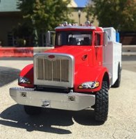
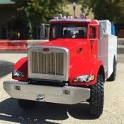
Hello model builders, After a few weeks of rain and clouds slowed down painting and progress, I was able to finish this project, and as today was sunny, well, the truck and I went for some pictures. If you're interested in seeing the process, please see the following: And on we go: As you can see, not a subtle truck - this is model of a Kenworth 963 Super. These are all wheel drive, heavy construction/oil field rigs - the tires/tyres are 6'/2m tall! This project involved a fair amount of scratch building. The front axle is from KFS but the suspension is scratch built - as is the hood/bonnet, chassis and bed. A guy went ahead and made the butterfly operable, using small piano hinges. And a couple of indoor pics - no distractions or bright paint: I really like how the bed and winch worked out - those of you who build model race cars might recognize the the cable - the same Top Studio we use for the hoses on 1/20 F1 cars - worked perfect for this! The tires/tyres are supposed to be used for a 1/16 scale model MATV - they are resin and quite heavy! And for fun, I cutout some images and set them in the appropriate landscape: And there you have it. I'm a bit disappointed this project is done, I really enjoyed it - ok, thanks for having a look. Cheers Nick
- 18 replies
-
- 26
-
-
Beautiful build - very nice! 😀
-
I'm glad to know that fellow builders enjoy seeing some of the real world too! It can become too easy for me to stay huddled over the model, fussing about with things that I enjoy, that really have nothing to do with the bigger picture, specifically, the 1:1 world! @busnproplinerfan, hi Bus, yes, I'll look around my work area and try and find the producer of those eye bolts - I really like them, and they took a long time to find! I usually use them for suspension and steering parts, but as you'll see below, they did the trick here too. @dnl42 😄- yes, the joy of painting! My advice here is to just keep trying - I know that sounds obvious, but it helped me. Over time I have become a lot more strategic about painting than I was when I started. By that I mean remembering what did and didn't work, and planning ahead, in terms of the actual painting process, masking things off in an order that works for you (or me!) and reassembly, and as you highlighted above, figuring out the best way to hold objects while painting. (as shown above, well, sometime bad thigs still happen! 🙃) Having now painted a few kits, I think about this well before I go about painting a project. I can advise to not rush - for whatever reason, in the past I felt obliged to really attack a model with paint - moving rapidly with primer and paint. I concluded that this approach leads to problems (for me anyway). Instead I try to take it easy, dusting on and building up colors, even taking a few minutes between sprays/coats. This has resulted in fewer blobs and streaks, and better overall coverage. I also try and paint in sunlight (in my mind this seems like something I would have read about, saying not to do this, but I do it) - as the actual results are much more evident than when painting in the shade. While moving at a moderate pace, I am not moving slowly, so there doesn't appear to be an effect caused by the sunlight - such as paint drying in irregular patterns etc. As for what works best for you, just keep at it, and you'll find an approach you feel good about. Once the paint above set up, I went about refinement by adding PE and whatever bits needed to be attached, and painting on some chrome: The hood/bonnet and air cleaners are still only dryfit, but they fit. The only strange turn of events I experienced, is that the "wings" on the hood have flattened out. That is, when I built them, I established some gentle curvature to match the cab and radiator shell. The match was spot on as unpainted styrene, but the fit is less close now. I have tired to recurve the material, but have concluded that I can live with this fit. I'd hate to cause more visible damage in the process of readjusting the parts. I am pleased to report that the hinges work fine, and happily, I was able to maintain a nice distance between the parts with layers of primer and paint now applied. I scraped the paint off of the small "bridge" that runs between the cab and nose, and dis the same under the hood/bonnet. I'll use regular styrene glue to hold the two together. I thought about using CA, but as the hood folds upward on both sides, I think that it would eventually snap apart. @busnproplinerfan, Bus, you can see how the eyebolts worked out as stanchions. And as noted before, the chrome/silver - still just OK, and not brilliant and chrome like. Also, as you asked about before, the grill mesh worked out too. I found some PE specified to be used for model truck radiators. By itself, the screen/mesh was too wide for this, but, it has a vertical bar in the center, which I planned for, by adding .02" x .02" vertical sticks, at the centerline of the opening when I built the nose. You can see them best in some of the process photos. I then cut the radiator mesh on each side of the vertical center, and glued the center bit of PE in place over the now painted "sticks". Then went back and cut the remaining mesh to match the width of the openings on either side. Not exactly easy to do, but the results are OK with me. The mesh was hard to cut, and I don't enjoy gluing parts with CA onto paint, as the slightest error can look awful. Happily, no catastrophes to report. Naturally, I had to dry fit this and see how it worked out: These giant photos seem to be good and bad - you can see it all, and you can see it all - the good and the less good. There are few areas on the engine that need some touchup before more weathering. As a side note, the older 953 version of this truck had radiators on each side of the "nose". Apparently as an homage to the 953, the 963 design keeps the nose shape, but only has the single, central radiator. As for next steps, I am waiting for more primer and paint to arrive for the bed, so in the meantime I'll add a faint dust wash to to the engine, chassis, and tires/tyres. My idea being that this tuck might have seen some miles, but, it is taken care of. The size of the tires remains intimidating, as I have added washes to many resin tire and wheels before, but they are very small in comparison. With other tires, I use a specific method for getting enough "dust: (Life Color Dust I acrylic) on to dull things down, but not so much as to look like the vehicle has just rolled in from the desert or a mud patch. Thanks for having a look - Cheers Nick
-
Well gents, I've stuck with painting, and for the next few days, the weather is said to be glorious, including this afternoon: So, this morning, in earnest, I went about detailing the parts I will share below, but along the way - it occurred to me to get a life! As I was sitting at my workbench, drinking coffee, listening to music, with an optivisor firmly attached to my head, and model parts in hand, I happened to look out the window - and well, it was sure a nice day! And as it turns out, I live pretty close to the San Francisco Bay, so a guy concluded that well, I could sit inside, and keep going or...."GO OUTSIDE" I know, crazy talk, but that's exactly what I did - went to the marina, went for a walk, got some sunshine and fresh air - even treated myself to lunch! I almost forgot, the 1:1 world can be pretty nice too! And not to worry, some of the news stories you might have heard about the demise of California, they might be exaggerated. On the left you can make out several towers of the Bay Bridge, with the San Francisco skyline in the background, and on the right, the Golden Gate Bridge - with Treasure Island in the middle ground on the left, and Alcatraz in the middle ground on the right. And it was warm, with almost no wind - as you can see by the still water - indeed, a glorious day! OK, enough fun and games, and back to serious business - model building. Over the last few days I have stuck with my regiment of running outside to paint between rainfall, and was able to make some good progress: Very much to my surprise and delight, the paint went on well. This is Tamiya Italian Red over, Tamiya Pink Fine Primer. I'm pleased, if not shocked to report no runs, blobs, streaks or orange peel. And made some headway on chrome parts: As this image is zoomed in quite a bit, you can see some seepage of CA from the eyebolts onto the handrail, but in "real life" this is unnoticeable. For this I went with Tamiya grey Fine Primer, followed by Tamiya Bare Metal, and then, using an airbrush, Vallejo Metal Color Chrome. While this is "fine" for this, application, it would not pass on a classic car, race car, or hotrod. The color looks more like stainless steel or bright silver. I understand that Alclad would have probably been a better choice, but I also understand that those colors are quite fragile, and probably not ideal for a guy like, say, me: Oh, what a treat - you might have noticed these two air cleaner housings in the group photo above - all painted up with that Tamiya Pink - ready to get hit with some of that nice Italian Red - easy enough! Except, as I was outside, merrily painting away, confident of more great results - well, both fell off of the wire I was holding them with - not to worry, the concrete sidewalk below broke their fall(s), and just to add some real interest, knocked off one of the intake tubes! Not only knocked it off, but pulled it and the styrene it was glued too :clean" off! Ahh - what a delight. As the disaster was obvious enough, I went ahead and picked the parts right up. Maybe you noticed my fingerprints? A real surprises is that despite this calamitous event, none of the numerous PE parts (there are several small clasps and brackets out of view) were damaged - there you go. So, before treating myself to a nice walk along the Bay, I cleaned up, fixed, and repainted them! Now, adding PE, painting on more chrome etc. to the cab and hood/bonnet. I ran out of paint and primer, so the bed will have to wait for a while - OK gents, thanks for having a look - Cheers Nick
-
Continuing with paint, and rainstorms - both have been steady. As such, I have continued with my unconventional approach to painting - wait for the rain to stop, run outside and prime, wait some more, run back out and add a base coat and repeat. And while a bit erratic, I have been able to get some basically good results. I painted the engine in-frame, a bit like an armor project - tape/mask off parts I don't want to paint, then hit it with Vallejo Sand (Ivory) with the airbrush to match Cummins tan. Then went back and picked out some hoses, wires and other odds and ends with various shades: I'm pleased to report there was very little overspray - in obvious, and less obvious places - which was a nice surprise. Then, those Tires/Tyres and wheels - well - quite a PITA. Having made several armor kits, I've worked with several sets of resin wheels etc so this process is not new to me - but, as these are so big, no fun at all. Primed with Tamiya fine pink, then templates made for each wheel - then red via rattle can, then painted the adjacent sidewall with a brush, then, paint the tread with an airbrush. The flip over and repeat for each - or until you don't want to paint anymore! The steps are hand painted using a blend of Vallejo Steel, and Vallejo Metal Chrome, and I am pleased with the results. As you can see above (pink primer on the insides) I didn't paint the wheels at once - it was very slow going. Once wrapped up, on to some of the frame accessories: Happily the paint went on to the frame accessories much more easily and consistently than on the wheels - who knows why? same primer and paint - but this is a good sign, as the cab and bed are built of the same materials. Next will be the cab interior, body and accessories. Thanks for having a look - Cheers Nick
- 109 replies
-
- 12
-