

Chewbacca
-
Posts
1,946 -
Joined
-
Last visited
Content Type
Events
Profiles
Forums
Media Demo
Everything posted by Chewbacca
-
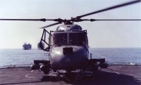
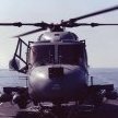 Thanks Colin. It's a shame that now the cabin is complete and the roof added, it really is so dim in the back that a lot of those details will be really hard to see. Bit like the Airfix 1/72 Jetstream that I converted to the T Mk 2 in which I flew my Final Air Test on 750 Sqn. Scratch built all of the back end with the student consoles drawn from images in the Aircrew Manual but the windows are so thick it is impossible to see anything inside. Perhaps I need an endoscope and screen for when I show these models at local model shows! In a way though it's helpful. It wasn't until I took those photos in the last post that I realised that despite all of my detailing of the winch, I'd completely neglected to fill the sinkhole on the side of the drum housing. Doh! Now I know that there are always limitations caused by the moulding process, but what on earth were Airfix thinking with the engine bay covers? Where has that curved seam come from? I don't accept that it is just a moulding line - that would be straight - but it doesn't look like anything on any Lynx I've ever seen. Now I do accept that there is a line of rivets just above the vent (still to be fitted in the position indicated by the hole) but that is straight! And in any case there are loads of rivets all over the side of that panel which have been left off as you can see in this image of XZ 233 resplendent in the dark blue livery in which it was sprayed to mark the 40th anniversary of the first Lynx flight in 2011. Removing the seam line was straightforward. Adding the rivets will be less so. I know I could get a set of Archers but there are so many rivets there that I may be a task too many. Haven't made the final decision but currently I am 90% certain I will leave plain. I do need to scribe in the engine bay cover release handle. It's not very prominent in the dark blue; it is on light grey! While still on the engine bay covers I turned my attention to the vents. Some were opened up (though far too small) and some were covered over. All needed opening up. Looking aft. On the right is the standard kit offering, on the left it has been opened up. Looking forward. On the left is the standard kit offering, on the right it has been opened up. And at the back end of the engine bay covers are 4 grilles, represented by Airfix by the 4 ovals seen here I have opened them up with a drill and filled the opening with offcuts of White Ensign Models' 1/600 flight deck netting. Then came close to a visit from Mr C*ck-Up. With the varnish matt coat dry on the interior I fitted it to the starboard fuselage side and had the adhesive on the cocktail stick ready to apply when I realised I hadn't fitted the footwell windows. Fortunately it was only on the cocktail stick and not applied to model but it was close! Both footwell windows now fitted (and already masked - there's precious little contact point and I didn't want to be pressing down with a blade later on) and the interior fitted to one side. When all is dry I will mate up the other side. Thanks for watching
 -
No, the handle was fixed and extremely close to the door in reality. Mine sits just proud of the inner bulkhead and given the thickness of the fuselage I think it would clear, but since the door is going to be open anyway I'm not overly concerned. That said, I may need to temporarily fit them closed to ease the masking process...
-
Thanks Loren And that's the cabin just about complete. Need to give it a spray with matt coat to flatten where I've got the odd errant spot of CA and fit the roof but otherwise I'm pretty much ready to move on with the next stage of the build. For the astute amongst you, yes the heater trunking is too short. Not sure why - I measured twice and printed once but it's still about 5 mmm too short. They should go to the aft bulkhead. Similarly the hydraulic pipes for the winch are cut off a little bit too short. They're made from stretched sprue and unfortunately the first one snapped as I was feeding it through. To be perfectly honest, I don't think anyone will be able to see it. With hindsight, I should have fitted the winch drum in the winch because if you look from the underside, you can see the gap. But it's too late now. Thanks for watching
-
Well the good news is that I found my Op Granby planning chart (along with my plotting board, Dalton Computer and whole raft of other stuff from my flying days that I thought I'd disposed of when I left). So I can now print a 1/48 scale version of this to sit on the instrument coaming. I've added the 3-man seat and scratchbuilt the backrest over the broom cupboard and 3-pint harnesses, though to be fair when I did a dry fit with the fuselage sides in place, it's quite dim in there (just like reality0 and I'm not sure that very much of that will be visible. Either side of that seat is a cabin heater outlet which bleeds air from the engine (and stinks to high heaven - used to give me a headache within about 15 minutes every time we turned it on). Notwithstanding the comment above that I am not sure how visible these will be, they are quite prominent as shown below so I have drawn and printed them. They're currently in the spray booth. Can't work out what colour that rubber flexi joint is between the two jubilee clips. S sort of orangey/browny/red! This is why I was never any good at art at school. And while sorting the cabin, I thought I would tidy up the winch. You will recall my comments earlier that we did fly with the winch almost all of the time because it was a right royal pain in the proverbial to fit at short notice and could almost guarantee a hydraulic leak. But it is going to be stowed so I'd 3D printed an unextended actuator jack with the correct open handwheel. But I needed to cut away the jib and reposition that at the lower stowed angle. Hydraulic pipes added - they will be tucked into the sound proofing as per the real thing when I fit the winch. If anyone is going to do this version, don't forget that the hook hangs vertically from the winch head so the attachment lug needs cutting away and the hook tacked on with CA until it hangs at the tight angle. Thanks for watching
-
They're perhaps a little on the large side but not overly so to my eye. Especially around the tail pylon they are quite prominent. The photos in the Lynx gallery here give you a reasonable idea. People forget that the Lynx was a rugged beast that the naval variant at least was tested to withstand, IIRC, a 14G vertical landing (a lot more than my spine could ever have coped with) so it did need a fair bit of holding together! Hope that helps. I'm getting quite worried now. There's only 2 months to go, I'm on holiday for 2 weeks of that and I've got shed loads to do.
-
Unfortunately not too much time at the bench yesterday but sufficient to move the NSM 3179 remote handset to the armament panel and start adding the cabling to the Sea Skua SUL/PSUL. There are still a couple of plugs on there and I know where the cables from those should go, but can't yet work out from the photos how they get there! Will need to do some more research. I've reprinted the Tektronix 212 remote spectrum analyser in a range of smaller sizes to see what will fit. they are now curing. I've also drawn and printed an MS6 six man liferaft cannister. I honestly cannot remember whether we flew with it strapped into one of the rear seats or not during Op Granby. It was usual that we did but I may have elected to leave it in the hanger and prioritise to another 25 kg or so of fuel. Thanks for watching
-
Managed a good few hours at the bench yesterday but it was a case of one step forward, two steps back so progress was slow. The problem was that getting parts to fit was a little challenging, mainly the main support hoop aft of the seats. Because with the seats fitted, the rear of the frames overlapped where the base of the hoop connects into the floor and try as I might that hoop was not going to fit without copious sanding. It also didn't help that either the hoop is too thick or the seats are too wide, but unfortunately where I had added the harness inertia ratchet locking handle, there was insufficient room on the Observer's sea between that and the hoop. In reality, there should be about four inches between them, certainly sufficient to get a hand/arm through, but the kit parts have then butted up tight. So I have had to move the Observer's inertia locking handle so that it sits slightly forward of where it should be. I've fitted the 3D printed Sandpiper Control Unit (CU) and NSM 3279 emote control handset on the side of the centre console. But I looked at it and found myself wondering, was the handset really there? It would be very difficult to reach below and behind the Sandpiper CU, but I do have photographic evidence to show it in that position. That said, that evidence is on an earlier configuration before I brought Sandpiper into service, and I do have another photo that shows an alternate position on a bracket on the armaments panel. I remember flying with both set ups but can't remember what BRAVE Flt had. With hindsight, I think it must have been the latter so I have removed it from the centre console, repainted and will put it on the armament panel. Throughout all of this I have been constantly dry fitting the cockpit/cabin parts into the fuselage to check that none of the modifications I have made will give problems downstream. And it was while trying to close up the fuselage around the hoop to check that the angle was right that I noticed a couple of nasty ejection pin marks either side that would not be visible when the fuselage was mated to the hoop and which sat probably no more than 0.2 mm proud, but that was enough to stop the fuselage mating. So out with the Dremel and sand the smooth. And finally a dry fit of the almost complete 3D printed NSM 3179 As part of the dry fitting process, I test fitted the Tektronix 212 remote spectrum analyser on top of the Orange Crop and then tried to locate the windscreen. Not a chance. I think the problem is that due to the limitations in moulding, the windscreen is significantly thicker than reality; at 1 mm thick it is the equivalent of 48 mm in real life when in practice it was a sandwich material no more than 5-6 mm thick. So even though I know that the 3D printed 212 is the right scale size (because I was able to download the spec sheet from the Tektronix website) the 3D printer is currently printing some scaled down versions at 70, 75 and 80% scale. I'll see which of those fits best. Interestingly, the fitting notes for NSM 3281, the GPS Trimble Trimpack, state that that equipment is similarly fitted on top of the Orange crop next to the remote spectrum analyser. And most of the photos also support that. But I was sure that my GPS was fitted on top of the radar. Sure enough, I was right and I have the proof! Thanks for watching
-
Seats just about finished. I'm quite happy with the way the 3D printed fire extinguisher came out. Needs a coat of matt varnish to hide the errant spots of CA. I then turned my attention to the instrument panel and added the homemade decal. This has been created from a combination of cockpit photos and drawn instruments taken from the Aircrew Manual so it is about as accurate as it can get. However, it was only after I came back when the decal had set and realised the deliberate error. Can you spot it? Here's the clue, an image I posted right back at the start of the build when I was modifying the instrument panel. The armament panel is raised up so I added a shim of plasticard to represent that, but for some bizarre reason I only cut it half height. Fortunately it was quite a simple fix to add an additional shim over the existing decal and then use one of the spare decals I had printed, cut out the armament panel and apply . It's not fully level but it's a lot better than it was and is probably good enough. I still need to add a tiny strip of 20 thou rod to represent the Master Armament Safety Switch and potentially a couple of small strips of 20 thou square section styrene to represent the covered weapon release buttons The wander lamp next to the radar was made from an offcut of 10 thou brass wire with actual lamp on the end made from 20 thou square section styrene. And while all that was drying I started assembling the 3D printed NSM 3179 Yellow Veil spectrum analyser and control computer to go in the cabin Not overly happy with the way that the decal on the front of the spectrum analyser has settled even with copious quantities of Microsol but I guess I was asking a lot of it to go over multiple knobs. Seats, collective and cover for the collective-yaw interlink mechanism have also all been fitted. Has to be said that none were a great fit and much fettling was needed to get it all to sit right and it is now all clamped while the cement on the pilot's seat sets. Thanks for watching
-
Almost there with the radome shape though still need to sort out a slight imperfection on the join between the two parts so thought I'd tackle the Orange Crop housing. I thought it would be easier to cut our a hole in the radome and then build up with plasticard rather than trying to replicate the complex curve with the bottom edge of the plasticard sheets. So first off I took measurements from the Aircrew Manual and drew on the shape, then chain drilled before attacking it with the Dremel to get the basic shape. I then added a couple of pieces of plasticard to represent the sides noting that at this stage they are higher than needed so that they could be cut back to size later. At first I thought I would add the front faces also before adding the actual antennae cut from kit part 12B I quickly realised that that wasn't going to work because the antennae were flush mounted so easier to use the kit part as the front face, so the front plasticard was discarded. Added a couple of fillets for the bottom of the front face underneath the antennae and a smear of Vallejo filler to blend them in. Will need a gentle sand later. And then added the top plate from more plasticard It was at this stage that I realised that in spite of taking the measurements from the Aircrew Manual that the angle between them must be wrong because there should be a small amount inboard of each antennae before each side joins together - this image of one of my earlier Flight cabs shows it very well: I'm not sure if the Aircrew Manual drawing is incorrect (shouldn't be I know but those drawings were originally done back in the early 80s before CAD), I transcribed the drawing incorrectly or, most likely, I failed to cut it accurately enough. I'm currently undecided. I may leave it as is. I may take it all off, open it up by about 0.5mm either side and re-assemble. While I waited for everything to set and then take that decision, I was spraying some more of the interior components including the winch. There is an online reference about Gulf War Lynx that states no Op Granby Lynx flew with the winch fitted to save weight. Poppycock. We had ours almost all of the time and needed it the night that one of our lookouts spotted a floating mine just ahead of BRAVE. We were able to manoeuvre out of its way and alert the tankers astern of us but in the chaos that ensued, the lookouts lost sight of the mine using the Electro Optic Sighting System. So we were scrambled to try to find it. We did so after about 30 minutes - which I thought was quite good at night - and marked it with a Marker Marine which was a six hour burning float. At first light we flew to a US vessel that had an EOD specialist on board; flew him to the mine, winched him down whereupon he attached some explosives and then winched him back up. I never told him that our winch was a little on the unreliable side and that if it didn't work, he needed to be a fast swimmer! We were back on deck and 3 nm away when it went bang and even at that range the whole of BRAVE shook. Anyway, I digress. I couldn't remember what colour our winch hook was. Most were red but there were a few that had more of an orange tint and I knew that I had a hard copy photo in a photo album of my then 5 year old nephew hanging in the strop in BRAVE's hanger in October 1991; that would prove it conclusively. Couldn't find that photo but did find another photo of 328 on deck which clearly showed that I had the shape of the Sandpiper mounting wrong. I drew it in CAD based on the sketch in the Aircrew Manual which showed it to be solid. That photo (which I only have hard copy so cannot post it at the moment) clearly shows the top of the mounting was a more open framework type arrangement. Therefore I redrew it in CAD and will reprint. I've also started on detailing the seats ready to start assembling the cockpit but haven't taken any photos yet. Thanks for watching, liking and commenting.
-
I can't help with the comparison because I haven't made the recent 1/72 version, but given all of the bad press that the original 1/48 kit had, I thought it wasn't too bad. Now in fairness it was one of the earliest kits I did after I returned to modelling after a lay-off of about 20 off years and I probably wasn't as critical then as I am now, plus I was used to the quality of Airfix from the 1970s which wasn't a great benchmark. Extremely unusually for me, I portrayed it as a Crab aircraft from 208 Sqn during Op Granby , purely because I had done a whole series of trials with the team on 208 the previous year and knew a fair few of them reasonably well. I took some photos of it a few years back but never got around to loading them online and since them have inadvertently deleted my entire Buccaneer folder. Must take some new ones.
-
Work on the nosecone continues with filling and sanding, reshaping filling and sanding. But I think I am getting there. Thought I'd add a coat of primer to better assess progress and I think I am getting close. Not quite there yet but not far off. A little more fettling to do and then I can add the housing for the fwd Orange Crop antennae. Thanks for watching
-
The moulding on the kit part for the blanking plate is slightly off centre to port, but the aircrew manual shows it on the centreline. This photo of BRILLIANT Flight rapid roping to our deck on the way south though the Red Sea in Jan 91 shows the position quite clearly. Currently though I think I'm minded to fit it slightly off centre and over the blanking plate for 2 reasons: I'm not overly enamoured at the prospect of having to recreate new lines of Zeus fasteners about 1 mm displaced from their current location I'm not one of those modellers who ever place their models on a mirror. This will be on a flight deck base with the nose wheel fully compressed. It will be almost impossible to see it. But I'm undecided as yet so watch this space. I suspect my accuracy OCD will kick in and I will have to put it in the right place!
-
Nowhere had any Hu87 in stock so Vallejo London Grey it is. It's not far off and in this scale it should be absolutely fine. So while I was waiting for the various bits to dry in the pant booth, I turned my attention to some of the other parts that need modifying to go from an HMA 8 back to a HAS 3 SGM. First up was the Tail Rotor Gearbox (TRGB) fairing. I think I wrote earlier that one of the problems with the early variants of the Lynx was that the designers at Westlands made the tail rotor rotate the wrong way around. For maximum thrust from the tail rotor in any helicopter, you want the blade at the front rotating up into the downdraft from the main rotor, in other words, rotating clockwise when viewed from the aircraft's left hand side. But like the Wasp, which also had this trait, Westlands had those leading blades rotating down through the downdraft, which meant that in order to generate the same thrust, the tail rotor had to rotate much faster. And that was what gave the Lynx its distinctive whine that could be heard from miles away. When I was flying I lived about 7 miles from the base and you could easily hear the aircraft ground running. My team on the flight reckoned they could hear me coming far sooner than being able to see me. Anyway, for the Army AH 7 and Navy HMA 8, Westlands decided to correct this. Allegedly, although I have never seen any written evidence to back this up, the first attempt to do this simply put one extra gear onto the TRGB thus reversing its final drive, but forgot that there was a worm drive for the integral oil supply. When they ground ran it for the first time, it supposedly disintegrated after about 10 minutes. I'm not sure I believe that but it was the apocryphal tale doing the rounds in the early 1990s (this was at the same time that the new helicopter they were building, the Merlin or to give it its correct title, the European Helicopter Industries 01, or EHI 01, became renamed the EH 101 when a lady in the typing pool inadvertently typed it incorrectly in a press release). The final solution for the direction of the tail rotor resulted in a bulge on the right hand side of the fairing above the stabiliser shown here cross hatched This had to go. I started with a razor saw but couldn't get a grip to start the cut on a smooth rounded surface and was in danger of cutting the wrong place or more likely my fingers, so out with the trusty Dremel (my children gave me a brand new cordless one for Father's Day back in June) which made short work of it. Then fill it with some shims of plasticard Add filler around the edges and over the top and when dry sand back down to form the shape. I won't know for certain how successful this has been until I get some primer on it but it feels pretty good so far. Next up was the nosecone. Notwithstanding the kind offer from a fellow member at Poole Scale Modellers who's a professional CAD designer to redraw the nosecone in CAD for me, I thought I would see what I could do by using more traditional techniques. So I started off by gluing together Parts 4A and 29C to form a Mk 90B nosecone. Then out with the Dremel again to remove the under chin 360 deg radome (oh how I wish I'd had a 360 deg radar when I was flying!) and reshape the front part of the nose to remove the flattened area to where they move the Orange Crop ESM aerials. And fill with plasticard shims/Vallejo filler. I'm giving that a full 24 hrs to thoroughly dry before I start to sand it back and reshape. Will then need to craft and fit a new housing on top of the nose to take the Orange Crop aerials. And finally, needed to modify the underside. For reasons completely unknown to me, the doppler aerials on the HMA 8 (highlighted in red) were moved aft to a position broadly in line with the main undercarriage. For all earlier variants the doppler was fitted forward of the nosewheel in the position shown in yellow. There were also two additional panels (shown in blue) that I think were an improved radalt. The Mk 3 radalt antennae were much smaller and were fitted flush, the two white dielectric panels in the lower photo to the left side of the doppler in the lower photo below. So again, "Dremel to Alert Five", "Action Dremel" and the doppler panel was quickly cut away, filled and the radalt panels sanded back Although I have kept the doppler antennae, as you can see they were fitted flush the fuselage so not sure at the moment whether I use that or not. I may simply create the antennae panels using a decal (to ensure I get that strange colour correctly matched) and then add the curved plate between the antennae from scrap PE. Thanks for watching
-
Sorry its been a bit quiet for a few days. It's silly season at work with people off on hols so we're a wee bit busy covering for them. I have managed to get all of the cockpit parts and most of the cabin parts primed and ready for first top coat. I'm wondering what the best representation of the mid grey is. I know that Airfix recommend Hu 87 Steel Grey. Not a colour I've used before so I'm not sure. I was thinking Vallejo London Grey which to my eye looks about right though may be a tadge light. I've got to pop out later today so if my LMS has any Hu 87 in stock I might try both and see what works best. The insulation matting in the cabin is another matter. What muppet at Airfix thought that that was Hu 78 interior green? I know Margate quite well as I was born and brought up in East Kent so I know it's not a village, but I think the village idiot must have written those parts of the instructions. As you can see in this photo taken in XZ 233 when it was on loan to the Yorkshire Aircraft Museum, the insulation is a silvery grey. I'm thinking a natural steel base with an darker oil wash. The other challenge this weekend is to find the Fablonned chart that I used in the aircraft during the war. I kept it because I thought it would be something to hand down to the grandchildren when they eventually arrive but for the life of me cannot remember where I put it. It used to be in the loft in my nav bag, but we cleared that out 3 years ago when we turned the loft from a layapart store into a usable bedroom/games room but I know the chart is around somewhere. Why is it important? Well if you look at this photo, it used to be stored quite prominently on top of my instrument panel and is very noticeable, so I need to photograph it to make a decal, and I need to start thinking about printing decals this weekend for the cockpit panels. Thanks for watching
-
That's very impressive. It just raises a few questions in my mind. Why can't I mask as well as that? Why can't I spray as well as that? Why do my decals not move like that without breaking? 😀 Seriously, that is very good but it would be very helpful if he listed what materials he used. We can all learn from each other.
-
Fairey Swordfish MkI +++FINISHED+++
Chewbacca replied to Ray S's topic in Here comes the Fleet Air Arm GB
Looking really good. Now if only those nice people at Airfix would upscale this to 1/48 -
That's a new one on me. Could you expand on what you mean please/ I would have thought soaking tissue paper in Copydex would mean that it would stick to the bays and be impossible to remove. Looking good.
-
Thanks Paul. I suppose a contemporaneous record has to be given a good deal of credence even though i agree with you that it certainly doesn't look two-tone top to bottom. Fortunately (or perhaps more accurately unfortunately) the decision over colour has been pushed right following as Lord Black Adder might have put it, "a visit from Mr C*ck-Up". I was starting to take the highpoints of the filler off before finishing with some 1/600 wet/dry when I noticed that the join between the aftermost straight hull section and the front tapered tail section had popped open and appeared to be weeping resin. My only assumption has to be that I didn't give it long enough to cure, but all of the components spent 24 hrs sat on the window sill in the conservatory followed by 30 mins in my wife's UV nail lamp. That was certainly enough when I did the 1/350 HMS HECLA last year and her hull components were much larger. I thought I would carry on nonetheless with sanding the rest and within about 30 seconds the aftermost straight section broke off. So at that point, I gave up and gave all of the parts another 24 hrs in the conservatory in bright sunlight yesterday. I'm hoping that will be sufficient. Thanks for watching
-
Thanks Martin. I knew that she was overweight and they took a whole raft of metalwork out to reduce her weight by IIRC 3 tons; I hadn't put two and two together and realised that that was the keel. Perhaps that would explain then why she broke her back when they moved her out on that fateful day in September 1911. Given that I plan to portray her on the floating mast when she first came out of the shed, I think I'll go with the earlier configuration and include the keel. And I would would never have thought from the photos that that was unbleached linen but knowing how much research you have done into all things airship, I am very happy to follow your advice. I should have taken a hint I suppose from the model in the Fleet Air Arm Museum: Thanks for all your help
-
Printed the keel and the gondolas. Had to print the keel in two halves - one printed fine the other had a couple of deformed girders so have repeated that and now have two good versions. Pleased with how the gondolas came out. I was half expecting the windows to not print and have to replace those with clear acetate sheet. And have got the first coat of primer on the keel and the hull, the latter primarily to show where more sanding and filler is needed. Not as much as I initially thought. At this rate, Mayfly is going to be finished well ahead of XZ733. But I'm about to hit a stopping point. What colour was she? Light grey or silver dope? Looking at the online imagery, I want to say the latter: Now interestingly, that photo doesn't appear to show the keel, yet this one does: I used this as the profile drawing which also shows a keel Yet this doesn't So I now don't know either what colour to paint her or whether I need to fit the keel! I think I'll head back to Lynx-land!
-
Well if we're thinking songs (beyond the Motorhead Bomber that I was planning to do), we've also got these by Saxon: 747 Strangers in the Night (Scandinavian Airways Flight 101) Motorcycle Man (type of bike not specified) Princess of the Night (all about an LMS Princess Royal Class loco - I'm sure the railway modellers must have something - if not there's alwsy the Combrig 1/700 HMS Princess Royal 😁) Dallas 1PM (Kennedy's Lincoln Continental from the old AMT kit) or there's Rush's Red Barchetta (which Scalemates suggests offers 40 different options!) This could get silly!
-
Think the final bits of 3D printing are now nearly complete and I can start actually assembling parts. The last few to be drawn were the Sandpiper EO/IT turret and associated electronics box, mounted on the inboard port weapon carrier and the Sandpiper control unit which mounts on the left hand side of the interseat console just by my left knee. As I think I said in an earlier post, my pilot and I used to leave our helmets hanging in the cockpit on the grab handles next to the engine control levers, so I had to draw a couple of Mk 4b flying helmets. Not easy in Fusion 360 - Blender might have been better but I think it's there or thereabouts. And my nav bag always used to be left in the Observer's footwell ready for a rapid launch so one of those is also being printed. I'll know in 2 hours if they've worked I reprinted the stabiliser when I printed some components for Mayfly and now have two of those ready to go. I think the only major part left to be printed is the replacement nosecone. Not looking forward to that. I had hoped to be able to repurpose the nosecone from the kit Mk 90 by cutting away the 360 deg chin radome and reshaping the underside but fear that might be a challenge too far. Fortunately a friend at my local model club is a professional CAD engineer who has offered to help. Thanks for watching
-
Airfix Leander and Rothesay conversions
Chewbacca replied to Gondor44's topic in Work in Progress - Maritime
It's bizarre. Until you first highlighted those viewing ports, I had never noticed them on any Leander (I've served in 2, landed a Lynx on about half a dozen and been onboard about another hlaf a dozen plus all the ones that used to come into Navy Days when I as a youngster!). Now they seem to be popping up in pictures everywhere. By the time you've finished, there'll be more filler and plasticard in DIDO than kit - just like most of my old Airfix 1/600 ships! But making excellent progress. -
Thanks. Done some more playing around with the gondola CAD. This looks more like it I think:
-
Thanks for that. Useful site for a variety of potential issues. The bizarre thing with that nose cone is that it is only a set of visual lines which are actually exaggerated by the macro photography - running a finger over the supposed layer and there is barely any ridge and what is there will come off easily when I take a sanding stick to it to smooth off where I have removed the attachment points. All sections are now printed and have been removed from their supports. I thought I'd be clever and aid alignment by including plugs and sockets on either end. Unfortunately, although the attachment plugs are fine, I don't think I left sufficient extra space on the sockets to allow for the print tolerances and none of them fit. Male end (the bits you can see on the inside are shavings where I have already sanded the attachment points from the other end) Female end You can see the central socket but it is fractionally too small for the plug on the other end. The sockets around the edge are barely discernible but then they are only 0.3 mm deep. So in the end I sanded off all of the attachment plugs and decided to rely on butt joins instead. My original plan on doing this was to print all of the frames and join them with 20 thou evergreen strip. I'm glad I didn't or I would have an awful lot of sockets to neaten! And then assembled the basic structure The fact that I don't have any alignment plugs shows itself in this photo as trying to align the different sections perfectly while the CA sets was a little challenging. This was made worse by the fact that the sides of each section aren't entirely parallel. I think it must be printing tolerances but all of the sections have a slight variance in diameter from one end to the other. It's not a lot - probably 0.1-0.2 mm - but it's enough to demand a bit of sanding on each of the 12 faces at each join. This is the worst example: I've aligned them all on one side which will become the top and left the misalignments on the lower side where hopefully if my sanding isn't perfect will be less noticeable. It's surprisingly light - much lighter than I was expecting - so I am now hopeful that the gondola supports when fitted may actually take the weight without the need to drill and fit clear perspex supports. Next job with this once the body (hull?) sanding is complete is to print and fit the keel plus finish drawing the gondolas for which I am struggling to get the shape from the photos. I do have one drawing (below) that shows the plan of the gondolas, but that doesn't align with the photos that appear to be more rounded, at least at one end, nor the large scale model at the FAA Museum which are a very peculiar shape. I shall continue to investigate FAAM model forward gondola FAAM model aft gondola This is the render of my initial attempt from the photos. More effort needed! Thanks for watching


