


eweidenh
-
Posts
12 -
Joined
-
Last visited
eweidenh's Achievements
")
Newbie (1/9)
4
Reputation
-
Curtiss 1908 "Number 3" Engine Model/ Research details.
eweidenh replied to eweidenh's topic in Classic - up to 1968
Thank you! Please let me know if you have issues with any of the parts. -
Curtiss 1908 "Number 3" Engine Model/ Research details.
eweidenh replied to eweidenh's topic in Classic - up to 1968
Thanks. I'll try again. .... should work now. -
Curtiss 1908 "Number 3" Engine Model/ Research details.
eweidenh replied to eweidenh's topic in Classic - up to 1968
Here is an overview of what I know about the engine. The citation "BAEA" is for the Bulletin of the Aerial Experiment Association. This has been digitized by the Smithsonian, but is only available through a library subscription. I have cropped, credited, and linked the images posted below. Hopefully this falls within fair use. Fuel system: The fuel is supplied by a partitioned tank, suspended overhead, that also supplies the oil. The tank held ten gallons of fuel and two gallons of oil. The original tank and radiator are on display at the Alexander Graham Bell National Historic Site in Baddeck, N.S. When the engine was first produced it had one aluminum carburettor on each cylinder. This was later changed to a conventional manifold with one carburettor per bank. These two images show several of the changes described below. They are cropped from: Smithsonian NASM-CW5G-0908, taken on 4 Nov 1908 and Ingenium CAVM-15495, taken on 2 Mar 1909. Cylinder and valves: The cylinders are of cast iron. The piston stroke is 3 3/4 x 4. The casting process was unreliable. On 19 November 1908, when the engine was installed in the Loon hydroplane (i.e. the AEA June Bug with pontoons attached) for a trial run, a flaw in the casting caused it to shed a piston. It seems that two types of valve domes were used. The heads were made by the H. H. Franklin Manufacturing Company of Syracuse, New York. The early type of valve dome used two studs to secure it to the cylinder head. On 24 November, 1908, Curtiss noted that these tended to pull the metal of the cylinder head out of round and cause it to leak (BAEA XXI 1-28). In later photos, these have been replaced by a version with a flatter exhaust port and without the studs. This change was likely made when the mechanical intake valve was added in December of 1908—see the comparison image above. The initial version of the valve dome used a suction valve for intake and a mechanical exhaust valve. The suction valve was replaced with a second mechanical valve at some point around 9-14 Dec 1908. this was a concentric valve configuration shown in this image which is from: L. R. Evans, R. P. Lay and R. C. Carpenter "TEST OF A 20-H.P. FRANKLIN AIR-COOLED MOTOR." Transactions (Society of Automobile Engineers), Vol. 5 (1910), p. 79. Crankshaft: The crankshaft was a hollow and made from vanadium steel. It is shown in the following photo (BAEA XXXVI p. 38, from the Smithsonian's Selected National Air and Space Museum Library Periodicals, Evolution of Flight, 1784-1991 archive): Ignition System Ignition was by dry cell battery; no magneto was mounted. Experiments performed on 4 February 1909 showed that the batteries were considerably affected by cold. (BAEA XXX 19). The distributor caused many problems over the life o f the engine. A major loss of power was attributed to slippage in distributor cam (BAEA XXXVI p. 38). At some point, the location of the distributor was switched from the non-drive side to the drive side. Perhaps this was done to make way for the flywheel that was added when the belt drive system was swapped for a chain drive. I don't know the firing order for this engine. The firing order for the later OX-5 engine, set up for counter clockwise operation, is: 1, 6, 3, 2, 7, 4, 5, 8 (thanks to jeaton01 for that information). This seems to match archival photos, keeping in mind that the distributor was relocated so the electrical connections are reversed relative to the distributor. Cooling System and water pump Each cylinder was surrounded by a thin copper cooling jacket. These had a tendency to leak and to burst when the liquid inside froze. The water was circulated using a gear-driven water pump. This does not survive, and is barely visible in the archival photos that I have seen. The info below is my best guess based on the surviving evidence. The pump is driven by an open gear (~60 to 65 teeth) running off the timing gear (90 teeth). In early photos, this was offset towards right cylinder bank (see Ing KM-40). This was later moved to a central position directly above the timing gear. Perhaps this was to equalize the pressure on both channels. The water pump brings cooled water from the radiator through a hose attached to an upward-facing opening and forces it down two curving channels leading to the lower water manifolds of the cylinder banks. The height of these curving channels delimits the circumference to the impeller housing the pump impeller, at lease the top side of it. Cooling water from these channels enters two manifolds, one on each lower side of the cylinder banks. It is forced upwards through the copper cylinder jackets and exits through the upper drive side manifolds which are joined by a hose at the drive side. This brings hot water to the radiator. Note that the original square Wright type radiator, presumably built by Curtiss, was swapped for an automobile radiator, built by the A. Z. Company, in early March of 1909 (see Smithsonian NASM-CW5G-0911, which was taken on March 17, 1909). The latter provided better cooling. The water cooling manifolds were modified over time. Earlier photos show threaded connections (see Smithsonian NASM-CW5G-0903). Later images show that these were replaced by soldered connections (see Smithsonian NASM-CW5G-0917). This change was probably made mid-January 1909 (BAEA XXX p. 10). Oil System The engine employed a total loss system fed from an overhead tank. There are various elements of the lubrication system located on the surviving engine, but I don’t have a good overall understanding of how oil was fed to the various bearings. Historical images show adjustable valves along the top of the engine that probably regulated the flow of oil to the valve gear. The published description in Scientific American on December 12, 1908 (p. 434) notes: "The main bearings of the crankshaft are continuously flooded with a bath of oil by means of an oil pump of the gear type." This was probably located in the sump. Drive System The first system used was a belt and pulley system incorporating two belts. After test flights began, this was quickly increased to four in mid-November of 1908. At that time, plans were made to switch to a chain drive and to add a balance wheel (BAEA XX p. 9). Parts for this were ordered and arrived in January. this was installed on February 23rd, 1909. At that point, the gearing was 18:24 (BAEA XXXIV p. 28)—see the comparison image above. -
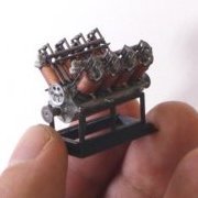
Hi All, This is s 3d-printed model of the historic "Curtiss Number 3" engine that powered the AEA Silver Dart, as well as several other experimental craft. It wasn't a reliable engine, but it was an important step towards the development of reliable V-type aircraft engines in the US. The surviving engine is an important artifact in Canadian aeronautical history because it powered the first flights in Canada on Feb 23rd and 24th, 1909. The surviving engine is heavily deteriorated, and there is little archival evidence for certain missing parts, so this is a recreation. The model is based on a scan of the original artifact that was made at Canadian Aviation and Space Museum (CASM) on October 22nd of 2019 by members of the Ingenium conservation team. That scan provided dimensional information for a CAD model that I designed in Fusion 360. The model is published on Thingiverse, along historical details, instructions, and information on the project. The model can be printed using any reasonably recent and decently calibrated FDM printer. The version show above has both FDM and SLA-printed parts, as well as some scratch building for the pushrods and ignition cables. Thanks to everyone who provided information on the previous post. My image links disappeared, so I thought that I would repost the completed model with image links from a (hopefully) more reliable source. Below is information on the engine that I have compiled for future reference, and in case anyone would like to contribute further.
-
Looking for help on early (1908) Curtiss Engine
eweidenh replied to eweidenh's topic in Classic - up to 1968
Thanks again to all who have helped so far. I have received a couple more archival photographs since I last posted. None offer a clear view of the entire engine. I did encounter this photo of the drive shaft, which supplements jeaton01’s firing order diagram posted above. This is from the Bulletin's of AEA digitized by the Smithsonian (university library subscription only). .... The gear-driven water pump on the non-drive side is especially unclear. Here are the details from the various images of the engines in (or near) its relevant configuration that I've found so far: .... I don't know much about centrifugal water pumps. This images below show my best guess for those missing elements so far. I’d appreciate any advice that you might have. Here’s a design and test print of the centrifugal pump recreation, which is based on the images below it. Keep in mind that the design is pretty coarse because it is designed to be FDM printed at 1/8 scale. Below is a rough FDM test print with the recreated elements painted green: Here's what I think is possible to know based on the information from the archival images above. This is a centrifugal water pump with two delivery pipes, likely emerging from a single point in the volute. Curtiss would later a patented a similar-looking water pump, but that had two separate intakes and chambers so that the pathways between the two banks were further separated. The water pump is driven by an open gear (~60 to 65 teeth) running off the timing gear (90 teeth). It is centred on the crankshaft. We can guess at its size and tooth count because it comes to approximately 2/3 the height of the carburettors. The water pump brings cooled water from the radiator through a hose attached to an upward-facing opening and forces it down two curving channels leading to the lower water manifolds of the cylinder banks. The height of these curving channels delimits the circumference to the impeller housing the pump impeller, at lease the top side of it. Cooling water from these channels enters two manifolds, one on each lower side of the cylinder banks. It is forced upwards through the copper cylinder jackets and exits through the upper drive side manifolds which are joined by a hose at the drive side. This brings hot water to the radiator. An earlier configuration placed the pump to one side of the engine, in front of one of the cylinder banks. I don’t know why this was abandoned. Possibly the different lengths of the two water channels created differences in flow to the cylinder banks. It’s also possible that the need to install clamps to prevent the solder joints around the cooling jackets from failing took over the place used by the pump. In any case, this gives us a maximum depth for the pump (assuming that the pump wasn’t changed) since too long a pump body would have intersected the front cylinder jacket on that side: Here’s what I think is a plausible configuration: Given the location of the centre of the gear driving the pump impeller relative to the curving channels leading from the pump to the lower manifolds, it seems likely that they join the pump at the top. The bends leading to these curving channels are probably sharp given the contiguous appearance of the arc of the two channels in some photos. The pump probably resembles various centrifugal water pumps designed by Charles B. Kirkham of the Curtiss Airplane and Motor Corporation. Here are some of those: The Smithsonian has a water pump from an OX-5, which you can see here: https://airandspace.si.edu/collection-objects/water-pump-curtiss-ox-5-v-8-engine/nasm_A19660385002 This is Kirkham's patented two-chamber pump. The images shows sharper elbow bends than the OX-5 pump. A couple of other things: - It's likely that this pump was made by another manufacturer, possibly an automotive company. For instance the concentric valve cylinder heads used in this engine were made by the Franklin motor company. I haven't yet looked into this possibility. - Probably the best image of the pumps comes from an early configuration of the engine when it was being modified at the Curtiss workshop. I don't really understand what's going on in this image. In particular, I don't understand this element highlighted in green. I don't think that it's related to the water cooling system, but I could be wrong. Maybe it's a piece of instrumentation for testing purposes? Electrical system is next... -
Looking for help on early (1908) Curtiss Engine
eweidenh replied to eweidenh's topic in Classic - up to 1968
Thanks very much! I was looking at the OX-5 and the V-4 while trying to figure out the gear-driven water pump. I didn't run into the handbook, which will be useful. I should get some detailed archival images in January from the CASM/ Ingenium archive in Ottawa. Hopefully those photos will show more detail. -
Looking for help on early (1908) Curtiss Engine
eweidenh replied to eweidenh's topic in Classic - up to 1968
Thank you all very much for your helpful replies! I'll keep digging around for better photos of the water pump. It's a mystery to me how it was mounted, given the surviving motor. I have a further question about the firing order of the cylinders: Do you know whether that was standard at the time? You can deduce part of it as there are a couple of photos that show wires leading from the magneto to the plugs. Also, assuming that the camshaft is intact, I could measure the angle of the rocker arms in the scan. -
Looking for help on early (1908) Curtiss Engine
eweidenh replied to eweidenh's topic in Classic - up to 1968
Second question: There is a row of alternating elements on the top surface of the engine case that are mostly missing from the surviving engine. These appear to be threaded plugs alternating with some sort of adjustable opening. Any idea what these these are for? * Detail from Smithsonian National Air and Space Museum archival photo NASM-CW5G-0917 https://airandspace.si.edu/collection-objects/aerial-experiment-association-cygnet-ii-propulsion-engines-curtiss-v-8-silver * Detail from Smithsonian National Air and Space Museum archival photo NASM-CW5G-0903 https://airandspace.si.edu/collection-objects/aerial-experiment-association-aerodrome-no-4-silver-dart-propulsion-engines -
Looking for help on early (1908) Curtiss Engine
eweidenh replied to eweidenh's topic in Classic - up to 1968
Here is my first question: There appears to be an additional assembly that is missing from the motor as it survives today. It looks to be gear drive--possibly an oil or water pump, though I'd assume that the oil pump would be inside the engine case. It's evident in various photos as a smaller gear above the valve timing gear, roughly in line with the lower portion of the carburettors. Any ideas or information on this? You can see it in the following images: * Detail from Smithsonian digitized journal "Aeronautics" Sept 1909. *Detail from Parkin 1964, p. 126. * Detail from Smithsonian National Air and Space Museum archival photo NASM-CW5G-0911 https://airandspace.si.edu/collection-objects/aerial-experiment-association-aea-aerodrome-no-4-silver-dart-mccurdy-john-d -
Looking for help on early (1908) Curtiss Engine
eweidenh replied to eweidenh's topic in Classic - up to 1968
The engine as it survives today is missing various parts, including spark plugs, electrical cables, cooling water tubing, and (I think) a gear-driven water pump between copper cooling jackets and radiator. I'd like to try to model a more complete version based on some archival research. This is challenging because: 1) The engine was modified pretty radically over its operational life. For instance, the engine that left the Curtiss Factory had one carburettor for each cylinder, one mechanical exhaust valve per cylinder (the intake valve was a suction valve), and the distributor located directly in front of the valve timing gear. The later engine had two carburettors (one per cylinder bank), two mechanical valves per cylinder, and the distributor moved to the opposite side of the engine. I'm more interested in this final configuration. * These are details from Smithsonian National Air and Space Museum archival photos NASM-CW5G-0908 and NASM-CW5G-0917 https://airandspace.si.edu/collection-objects/aerial-experiment-association-aerodrome-no-4-silver-dart-mccurdy-john-d-glass https://airandspace.si.edu/collection-objects/aerial-experiment-association-cygnet-ii-propulsion-engines-curtiss-v-8-silver 2) I haven't found a lot of photo documentation so far. 3) My knowledge of piston engines (not to mention historical aircraft engines) is very limited. I was hoping that some of you pros could help me with some technical questions, or provide suggestions about where to look for archival info. In any case, this topic should serve as a repository of info on this engine, which isn't particularly well studied. Here is how the engine was described in Scientific American on December 12, 1908 (p. 434). This refers to an earlier configuration as mentioned above. The engine of the “Silver Dart” is a 3 ¾ [bore] by 4-inch [stroke] 8-cylinder, water-cooled, Curtiss motor, capable of developing 50 horse-power at 1,600 R. P. M. Including radiator, water, oil, etc. the weight of the complete power plant is 250 pounds, but the engine alone can be stripped to 165. The cylinders are fitted with copper water jackets and auxiliary exhaust ports. Circular concentric valves are located in the cylinder heads, the inlet valves being automatic. The crank-shaft is of specially treated vanadium steel. It is bored out hollow and is 1 ⅜ inches in diameter. The connecting rods are steel forgings, the cylinders and pistons being cast iron. The crank case is made of special aluminum alloy. The main bearings of the crankshaft are continuously flooded with a bath of oil by means of an oil pump of the gear type. Individual aluminum carbureters are employed with all eight cylinders. -
Hello All, I'm new here. I hope that this is a reasonable topic for this forum. I'm working on a 3d-printable model of a classic aeroengine--basically an (intermittently) working prototype from the early history of aircraft. This is the Curtiss No. 3, which famously powered Silver Dart, Cygnet II, and various other experimental craft created of the Aerial Experiment Association (AEA) that included Alexander Graham Bell, Glenn Curtiss, and others. The engine first ran on 23 October, 1908 and was used by the AEA through at least February 1909. It was later used in a small fishing boat in Nova Scotia, which sank. The engine was later recovered and now sits in a display case at the Canada Aviation and Space Museum (CASM) in Ottawa. The good people at CASM made a scan of it for me a month or two ago. I've been using that scan as the basis for a printable model. Here's a rough 1/8 version FDM printed version in primer: Here's a 1/25 version in UV-cured resin that I've painted up:
-
Please delete.
