diablo rsv
-
Posts
908 -
Joined
-
Last visited
Content Type
Events
Profiles
Forums
Media Demo
Everything posted by diablo rsv
-
Martin B-26b Marauder ICM 1/48
diablo rsv replied to diablo rsv's topic in Work in Progress - Aircraft
I have made a start, just not where the instructions begin, which is predictably with the fuselage internals and cockpit. I felt that the kit instrument panel could be improved upon so I have ordered the Eduard photoetch set designed for the Monogram/Revell kit. With a bit of luck it will fit. I have also ordered the seatbelts from Eduard, I am surprised ICM didn't include belts. For the most part the details in this kit do look great and are perfectly adequate but I'm sure the aftermarket companies will be all over this one. So whilst I wait for the photoetch I decided to tackle the wings. The wings themselves consist of an upper and lower half with separate flaps and ailerons which are also split into two parts. The ribbed roof of the wheel well is moulded into the inside of the upper wing half... but if you look carefully you can see some sinking on the upper surface. It's only slight but it could show up on a bare metal finish. It's not very obvious in the photo but it will definitely need sanding. I decided that it would be easier to paint the inside of the wheel wells before joining the wing halves, and whilst the paint was in the airbrush it would make sense to do the insides of the nacelles and cowlings as well. The three vents make the cowlings quite a complex shape which would have been difficult to mould as one part so ICM have used multiple parts. This was the first test of the kits engineering and I'm pleased to say it's very good indeed. It looks as though, for the most part, the joints are on what would be panel lines. However I felt that, as can be seen in the photo above, the fit isn't quit good enough to be left as a panel line, so I shall fill them and rescribe as necessary. I just need to find some decent quality photos to see exactly which should be panel lines. I know in reality the panels weren't always a great fit but it's hard to portray that without it looking like poor modelling. Talking of joints on panel lines, the ICM plastic feels quite soft which means that care needs to be taken when using Tamiya extra thin to avoid molten plastic oozing out of joints. Of course the upside of this is that the oozing plastic is ideal for joining parts that are not on a panel line and makes for a seamless join. It looks as though ICM have thought very carefully about where to put sprue attachments and ejector pins. There a couple on the inside of the nacelle halves but they are easy enough to get to and remove. Once this was done I sprayed on some Mr Finishing Surfacer primer. The instructions call for the insides of the nacelles to be painted Olive Green, my limited research tells me that it was more likely they would have been Aluminium possibly with a protective clear coating. This seems to make sense so I used Alclad Aluminium lacquer. The ends of the exhausts really need drilling out as they will be quite visible on the model. The edges of the shrouds could also do with thinning down a little to give the appearance of sheet metal. A little effort made quite an improvement. Test fitting of the wing and nacelle halves showed that the guide pins are a tight fit in their corresponding holes, this was quickly remedied with 0.8mm drill bit. The fit was then perfect. Most of the panel lines are very well done but I'm not sure what happened here. I wonder if it's on all of the kits. Here are all of the wing components ready for assembly. The fit of the nacelles to the wings is almost perfect. Impressive engineering once more. As is the fit of the flaps apart from the gap between the aileron and the middle flap... I'm not sure if this is right. It's the same on both wings but I think it I will need to add some plastic strip to the end of the flap. I'm not sure what's going on with the landing lights either. I feel they could have made an attempt at adding some detail here especially as they are quite prominent and the inner faces of the housings will need some sanding. Here are the real ones for comparison. Not difficult to scratch build but a little frustrating, especially considering the detail they have put into other parts. Apart from the couple of niggles mentioned it does look as though this kit could be built into an impressive model without too much effort. The parts need very little in the way of clean up and the odd seem line can be dealt with vey easily due to the soft nature of the plastic. I'm currently working on the engines and hopefully will be able to make a start on the fuselage next week. It seems as though my mojo can be restored with this one. Wayne- 18 replies
-
- 10
-

-
Martin B-26b Marauder ICM 1/48
diablo rsv replied to diablo rsv's topic in Work in Progress - Aircraft
Thanks Paul, that looks really interesting, unfortunately I have something on that weekend. Thank you all for your interest, it looks like a great kit' hopefully I can do it justice. I haven't looked too closely at the Monogram kit, but I have heard of a couple of fit issues around the nacelles. Having said that there are some lovely builds of it on the internet and on his site. Google 'Britmodeller B-26 Marauder' and they will come up. You could always do a side by side build, it would be interesting to see how they compare. Thanks Andrew. I can't help myself, like most of us, I have more kits than I would ever have time to build, but every now and then one will come along that I just have to build. Always glad to have you along for the ride Roger. I really must finish this one though, they are starting to stack up. Thank you very much for the info guys. I bought the Warpaint book which has a list of production numbers. My short list of chosen subjects all fall in the 42-96029 to 42-96228 range which would make them B-26B-55s. You're right Martian, I just fancy having a go at one of the less modelled aircraft and attempting to create the nose art myself. In all likely hood that will be harder than I imagine and I will end up doing 'Big Hairy Bird', but that's no bad thing. Wayne -
Supermarine Spitfire Mk.IXC Airfix 1/24
diablo rsv replied to diablo rsv's topic in Work in Progress - Aircraft
That looks promising. I did consider something similar, but one of my concerns would be how well they would stick. I plan to use stencils for the markings and I'm not sure if the masking would pull them off. If you go for it please let me know how you get on. At the moment I'm thinking I need to do some research and find if any 'C' wings Mk.IX's had flush rivets. Wayne -
Supermarine Spitfire Mk.IXC Airfix 1/24
diablo rsv replied to diablo rsv's topic in Work in Progress - Aircraft
That's very interesting, I did wonder why they used a mixture of rivets. I have considered a few options. Skinning with aluminium foil embossed with rivets, but this is probably beyond my skill levels. Making rivets from lead foil, as @Jonners59 suggested. Using 3d decal rivets, such as the ones from HGV that @Ex-FAAWAFU has used. These look a little too small for 1/24th scale though. Archer make some, but these seem to be hard to get now, also they tend to come on strips so getting the spacing could be difficult. There is also Quintas Studios but these look a little on the small size as well. The option that I was thinking of doing was to use Anyz 3d printed rivets, there are 4 sizes of these. The other size is .35mm, which I already have, but these are too small. However they are not cheap, so I really need to work out which of the sizes above I would need. It does look as though they are all the same size on this fuselage..... ..but two different sizes in this one. I haven't counted them on the model but I would guess around 1000, hence the lack of enthusiasm. Or maybe I'm over thinking it, below is another of the Duxford Spits. I think it's a Mk.IX. I don't know the history of this particular aircraft, but for whatever reason when it was restored they used flush rivets. I think I need to find a decent image of my chosen subject but, I can't make up my mind on that either. Wayne P.S Immediately after posting this I did a search on Google and found these seemingly knowledgeable posts on a couple of forums. Key.Aero The riveting patterns on a MKII is the same as MKI, MKV & early MKIX's. Basically from Fr5 to Fr10 above fillet fairing line are csk rivets, below fillet fairing are mush-head rivs. From Fr11 aft the vertical frames are 3/32 mush-heads except Fr19 which are 3/32 csk rivs. along the spine they are 3/32mush-heads. The horizontal intercostals from Fr11 aft are 1/8th csk rivets, but you will have to dimple the skins & structure . Fr8 to Fr11 the horizontal stiffeners are csk 3/32 rivs, again skins & stucture are dimpled. Fr5 to Fr8 you can cut csk for 3/32 rivs. Fr5 side channels are 5/32 dia riv,again these are cut csk. Radio bay & battery bay doors are both 3/32 mush-head rivs. On the early MKs there were no doublers under the skin around the radio & battery bay door holes. RCU Forums Starting with the Mark I, the Spit generally used round-head rivets along seems where major panels attached to the major longerons and major bulkheads. In other words, along the outer edges of the panel. Flat head (flush) rivets were then used along the intermediate stringers intermediate bulkheads. I believe this practice was followed from the Mark I through the Mark V, as well as through many of the Mark IXs, since the early Mark IXs began as Mark Vs and were changed over to Mark IX configuration during assembly or in later retrofit. Later Mark IXs, and subsequent marks, used flush rivets throughout due to changes in fuselage skin thickness and improved manufacturing techniques. So it seems that I need to know if my chosen subject is an early or late Mk.IX. Given that I've gone for a 'C wing' I presume I am modelling an early Mk.IX and therefore raised rivets. -
Supermarine Spitfire Mk.IXC Airfix 1/24
diablo rsv replied to diablo rsv's topic in Work in Progress - Aircraft
Many thanks Charlie @Johnson, Keith @Keeff, @Jonners59 and Roger @Hamden Up to this point I have been thoroughly enjoying working on this kit, but I've reached a point where I need to make a decision. Do I replace the main rivets on the fuselage or leave them as is. I'm sure Airfix had their reasons but on a kit of this scale I really think they should have added raised rivet detail along the fuselage after all, it is quite a prominent feature on the real aircraft. Kotare did it on their 1/32 Mk1 kits and got round the problem of replacing lost detail on the seams by having a separate spine section. Maybe I'm being too picky, but I'm not sure that if I leave it as it is I won't regret not replacing them, especially after I have gone to all of the trouble of adding extra details else where. However the thought of drilling hundreds off tiny holes and sticking in tiny rivets fills me with dread. So I've put this one on hold for a little bit whilst I restore my mojo by building the ICM Marauder. Wayne -
I spent most of my early life living in the Essex village of Silver End and no more than a mile from my house was the former airfield officially named RAF Rivenhall, but to us locals it was known as the Silver End Drome. At that time it was occupied by Marconi and used for testing radar installations. As inquisitive kids and despite the security we would occasionally sneak onto the airfield to explore the area. Having always had an interest in the military I was aware that Marauders had been stationed there during the war and the type became a firm favourite of mine, so I have been eagerly awaiting the arrival of this kit, so much so that I have decided to put my Airfix 1/24 Spitfire build on hold and crack on with this one. @Mike has already done an excellent review of the kit HERE including sprue shots and a brief history of the aircraft so there is little point in me repeating it here but my personal view of the kit is that it looks very promising. Looking at the amount of parts I'm hoping for a mojo restoring straight forward build. I wasn't intending to add after market or go down the rabbit hole of super detailing the kit but I think the instrument panel could benefit with an upgrade... There aren't any seatbelts provided and as the plastic parts are beautifully moulded and very clear I will need to find something suitable. As for the guns and engines I think the kit items are acceptable. I'm struggling to decide which aircraft to depict. The decals in the kit look to be very good indeed.... ..however my subject would need to be from the 397th Bomb Group as it was they who were stationed at Rivenhall from April to August of 1944. The kit does include markings for the very colourful 'Big Hairy Bird' of the 599th Bomb Squadron, but this has always been a very popular subject in the modelling world. I have the very handy book from Bruce Stait 'Rivenhall The history of an Essex Airfield' which seems to be well researched and in it there is a list of the 397th Marauders, so hopefully with a bit more research I can find a suitable subject. My only concern is that the book states that the 397thBG were equipped with Marauder Cs and most of my references have them as Marauder Bs. I'm not sure if there are visible differences but I will have to build a B, I guess. I would really like to do a bare metal finished aircraft but with some interesting markings. The 397thBG were stationed at Rivenhall for D-Day so I think the invasion strips should add some interest. I like the look of the aircraft from the 597thBS so one of those would be favourite even though 'The Milk Run Special' has also been a popular subject. These aircraft certainly lend themselves to fans of weathering and that's the stage I'm looking forwards to tackling so I suppose I'd better go and get on with it. Wayne
- 18 replies
-
- 14
-
-
I have this kit sitting next to my bench ready to start once I finish off a couple of other projects, so I shall be watching with interest. Can I ask where you managed to find the book? It seems to be out of stock everywhere, although I believe Wingleader my be releasing something soon. Wayne
-
Supermarine Spitfire Mk.IXC Airfix 1/24
diablo rsv replied to diablo rsv's topic in Work in Progress - Aircraft
Thanks! @Shoggz That's very kind of you. As you will see in this post I think you may have had the right idea closing it up. Getting the cowlings to work hasn't been easy. First up though I tackled the propeller assembly. This was fairly straight forward with just the trailing edges of the blades themselves needing a bit of thinning down before they could be primed and painted. For the markings on the blades I wanted to use the stencils included in the 1ManArmy set even though the kit decals looked pretty good. However I made a bit of a mess with the stencils. Because I thought it would be difficult to get opacity in the pink and yellow over the black background I used white as an undercoat. I think this made the paint layers too thick and it looked awful. So I sanded the paint off of the blades, repainted them and went with the decals. The decals were a little on the thick side and the carrier film was quite obvious so I applied a heavy coat of gloss varnish. I then used sanding sticks to flatten the varnish. Once the flat coat varnish was applied the carrier film pretty much disappeared. There is a prominent panel line around the spinner which is absent from the kit one. So using a razor saw blade supported at the correct height I scribed the line around the spinner. The holes around the bottom of the spinner also need drilling out. The propeller hub is nicely detailed and once painted and given an oil wash looks too good to be permanently hidden away, so I added a magnet to the centre of the hub and spinner and that allowed the latter to be removable. Apart from some weathering the propeller assembly is finished. I knew from reading various reviews and builds online that having removable engine cowlings was going to be problematic. The kit has been designed in a way that makes it difficult to have a detailed engine and have removable cowlings. In fact they give you a basic engine block ,which is pretty much there just to support the propeller, if you wish to fit the cowlings. However I was determined to find a way to make them removable and have a detailed engine. Test fitting showed that there would be quite a bit of fettling to get them to fit in a satisfactory manor, the worst was the bottom panel. Some plastic strip added to the edges of the wing fillets closed up the gap. The next job was to do something about the exaggerated detail on the panel fasteners. On the real aircraft they sit flush with the panel. However on the kit they are depicted as a raised ring. I sanded off the kit detail and then using a burr made a hollow so that a disc of plastic card could be glued in flush with the panel. A hole was then drilled into the centre of the disc and a piece of plastic rod with a slot cut into the end of it was inserted into the hole to represent the screw. The upper and lower panels needed quite a bit of plastic to be removed from their insides and the side panels required some plastic strip adding along their top edges before I was happy with the fit. The next problem was how to get them to stay in place but be removable. I started out with micro magnets but the ones that were small enough to be discrete were too weak. Next I tried adding brass pins in a couple of places but the ones in the side panels by the wing roots just couldn't hold the panels in place. After a lot of head scratching I had to resort to using a couple of 0.8mm micro screws in each side panel. They are so small that it won't be easy to get the panels off and on but this isn't something I'm expecting to do too often. Hopefully they won't stand out too much once everything is painted. For the upper panel I glued a brass pin at the back which fitted into a hole that I drilled into the firewall. At the front end there is a moulded ridge that snaps into place behind the front plate. I glued a plastic tab to the back of the lower cowl and cut a slot for it into the bottom of the fuselage. At the front I glued another tab but with a hole drilled into it. A corresponding hole was drilled through the pitch control mechanism and I made a plastic pin to insert into the hole to hold the panel in place. Hopefully that all makes sense. It's not perfect but I have got removable panels that fit reasonably well. Wayne -
Supermarine Spitfire Mk.IXC Airfix 1/24
diablo rsv replied to diablo rsv's topic in Work in Progress - Aircraft
Now that I have the engine built to a level that I'm satisfied with I can set about getting it fitted to the fuselage. The engine support frame was assembled and painted without any trouble. I painted the cooling pipes with Alclad Polished Brass toned down with Mig Ammo Shaders Dirt and even though I added a protective clear coat the finish was quite delicate. I had seen a few builds online and knew that fitting the cooling pipes could be awkward so I followed the advice and cut through where the holed plate met the frame rail. The whole assembly was then fitted to the fuselage. Once the engine support was installed the front part of the wing fillets could be fixed in place. Test fitting showed that some work would be required to get a decent fit. There is a rectangular plate on each fillet which I presume is for access to the gun camera. As there is no camera on the starboard side I guessed that there shouldn't be an access panel there, so I took the chance that this is correct and filled it in. Getting the fillets to fit meant the loss of the fixing screws detail, which was absent from the top edge anyway. I drilled out .5mm holes and inserted plastic rod with a slot cut into the top to try to replicate the screws. It will require a little tiding up but hopefully they will look ok once painted. I wanted all of the components of the engine installation ready before I committed to fixing it in place, and so I set about getting the cowling support frame assembled and painted. There is a fabric strip (Hessian ?) fixed to the outside of the frame which I presume is to stop the vibration from the engine loosening the panel fixings. To represent this I first painted the frame a brownish colour and dry brushed it with buff. Then the exhaust heatsink was painted with MRP Burnt steel, this and the strips were masked off before the frame was painted with the darker mix of cockpit grey green. Finally I punched out rivets from some lead sheet and fixed them to the strips with some VMS matt varnish. The tatty hole in the centre of the frame below the exhaust is where I was trying to fix a micro magnet to help keep the cowlings in place. I have since changed my mind about that approach and shall tidy it up later. The carburettor air intake filter was the next part that I wished to add some detail to. On the real aircraft there is a noticeable adjustable flap at the front of the intake. I ground out some material from the inside of the intake and added a flap made from some sheet brass, I have also made the actuating mechanism from some plastic rod and sheet. The cable will be added once installed. I felt that the edges at the front of the oil tank were a little thick.... ...so I cut out the front panel and reduced the thickness of the walls with a burr. A new front panel made from plastic card and the rivets replaced. I'm not sure if it was worth the effort though. Finally the engine was fixed in place and the various pieces of pipe work and wiring added using a combination of brass, plastic and lead. This has by far been the most time consuming part of the build, but has for the most part been a very enjoyable experience. It certainly looks a lot busier than if I had built it straight out of the box. There is a little bit of touching up to do here and there and then I have to set about the next problem which is to get the cowlings to fit. Wayne -
Supermarine Spitfire Mk.IXC Airfix 1/24
diablo rsv replied to diablo rsv's topic in Work in Progress - Aircraft
Many thanks Chris @bigbadbadge That's an idea Roger but I think I will attempt to cut out the panel and replace it with something fist. Airfix customer services wasn't very helpful, basically they said that it's just one of those things and can't help me. I did wonder if I could contact the company that did the injection moulding for them and see if they have spares or message the vendor to see if they can help. Just to really naff me of I had a look at the canopy in my next project, which is the HK models 1/48 dambuster as the accuracy of it was being discussed by @elger on his build log, and guess what... it has a flow line in the windscreen. Maybe I've just been unlucky, but perhaps I should stick with AFVs. Anyway, back to the Spitfire. Airfix seem to have done a pretty good job with the engine and firewall details, all of the major components are there, but a lot of the plumbing and wiring needed to be added. My reference materials on this subject are limited so I relied on the internet and the odd visit to Duxford, however maintenance is limited to one hanger where it's difficult to get close up photos of the Spitfires with the cowlings off. Probably the most useful resource was the UK Aircraft Explored channel on YouTube, although the subject is a Mk.V it's very helpful in explaining what the components are and what connects to what. One of the components Airfix seems to have missed is the relief valve as seen in this diagram of the hydraulic system. I made one from some plastic rod, it's not great, but will hardly be seen in the finished model however it does provide somewhere for the pipe work to connect to. The filters needed a little bit of tweak and a T piece needed to be added below the reservoir all for additional pipework. I the used various thicknesses of brass rod and tube to connect everything up. A conduit for some cabling has been added and at this point I realised I had missed a sprue nub, arrowed in the photo below. I read somewhere that the green in the engine bay was often a little darker than that used in the cockpit so I added a touch of bronze green. I think that Airfix have made a lovely job of the engine and made up straight from the box looks fine. However, looking at one of my photos from Duxford I felt it needed to look a lot busier in the engine bay. I found a number of images on the internet, although not always the 60 series Merlin, that gave me enough of an idea as to what needed to be added. Most of the extra details are painted black and they do disappear a bit, but I believe they are a worthwhile addition. It's not a particularly accurate representation of the original engine but once installed it should look close enough. Wayne -
It's looking good, you're making much quicker progress than me, are you leaving the engine out? Sounds like you are not far from me, I am in Suffolk only about 20 minutes from Duxford, it's been pretty handy for when I need reference photos. Wayne
-
Supermarine Spitfire Mk.IXC Airfix 1/24
diablo rsv replied to diablo rsv's topic in Work in Progress - Aircraft
Many thanks once again for all of the encouraging comments. Yours do look a little fainter than mine Charlie, however they appear to be flow lines which go right through the plastic and would be impossible to sand out. I have been in contact with Airfix but their response was somewhat disappointing considering this is clearly a manufacturing fault. "Thank you for your email. Having had a look at the image you have supplied, as well as the stock of the same part we have available as spares, it would seem that all of the parts have this same marking on them, which would appear to be a flow line. This is sadly something which is common on clear parts, and something we would not be able to supply a part free from on this occasion I'm afraid. Having spent a fair amount of money on this kit and the aftermarket parts, plus all of the hours that I have already invested in building it so far, I am really frustrated. I will carry on trying to get a replacement but it's not looking good, so in the meantime I am trying to think of alternative solutions. Maybe I could cut out the panels and replace them with acetate, or as I have done in the past, microscope glass sides. At least I do have two to experiment with. Wayne -
Supermarine Spitfire Mk.IXC Airfix 1/24
diablo rsv replied to diablo rsv's topic in Work in Progress - Aircraft
Thankyou @crobinsonh. Offering the wings up to the fuselage revealed a bit of a problem with the fit. There was a noticeable step between the wing and the wing fillet which increased towards the front. On the actual aircraft there is hardly any step at all. To rectify the problem I removed some plastic from the bottom of the cockpit tub and a little bit from the bottom of the engine bulkhead.. Part of the wheel wells are on the underside of the wing fillets and needed to be painted before fitting the wings. The fit was much better but I still needed to scrape and sand down the top of the wing fillets. Airfix hadn't included in any rivet detail along this edge, presumably due to limitations of the moulding process, so I added these when I was happy with the fit. The fit on the underside was fine, just a little sanding and filling required. The trailing edges on the elevators and rudder were again too thick for my liking, so I scraped away some plastic from the inner faces and reduced them as much as I could. I fixed them in place with the elevators dropped as this seems to be the norm for parked aircraft. In the photo above you can see that the rib tapes are more prominent than what Airfix has depicted however I'm still undecided as to whether to try to replicate this. I did decide to refine the detail on the trim tab actuators with a little bit of plastic rod. I have also removed the moulded in tail light, this will be replaced with one made from some clear plastic. I presume this was an original feature. I wasn't happy with the shape of the front edge of the radiator housings, so I sanded these to better match the profile of the ones on the actual aircraft. I want to have the flaps on the radiator housings lowered but Airfix haven't included any details and this would be quite evident. So I scratch built the reinforcing plates, support arms and the actuators. I have also tried to replicate some of the paint ware on the inside of the housing where the flap rubs against it. And finally it's starting to look like a Spitfire. Next up will be the engine and bulkhead. I have found an issue with the windshield in my kit. There appears to be a crack from the bottom corner on each side. Airfix sent me a replacement but this one has the same issue. I would be interested to know if anyone else has this problem in their kit. @Billos @robstopper @noelh Wayne -
Supermarine Spitfire Mk.IXC Airfix 1/24
diablo rsv replied to diablo rsv's topic in Work in Progress - Aircraft
Thank you all very much, that's really kind of you. Hi Roger, of course, nice to see a familiar name from the AFV world. Thanks Keith, hopefully a lot of it will be visible when it's finished. The next part of the build was the wings. This starts with the placement of the spar and ribs, I basically followed the instructions here but I did make sure that the main spar was perfectly centred and that the wheel bay walls lined up with the opening in the lower wing before gluing. The wheel bay walls in the kit have some recessed rivets in them but looking at my references it's clear that these should be domed head screws. To replicate this I used some micro soldering balls such as these. Although not perfect I think the result is a definite improvement improvement even though they won't be that easy to see on the finished model. You can also see in the photo below that there are some ejection pin marks in the gun bays that needed filling. The guns were cleaned up and the barrels of the 303in machine guns were drilled out. These were then primed and painted in a dark grey. To give them a brownish tinge I used one of the Mig Ammo Shaders, I think it was the Earth one, and then gave them a brush with some graphic powder to create a metallic look. The Hispano cannons appear to be missing a raised lip on the top edge of the gun body, so I added these with some plastic strip and repainted them. These were then fixed into their gun bays along with the cooling pipes and ammunition, which I've hopefully painted in the correct order. The Airfix instructions would have you fit the lower wing to the fuselage before fitting the upper wing halves. I thought this would make it harder to resolve any fit issues so decide to join the wing halves first. Before that though I drilled out the fixing holes where the gun bay covers sit. The trailing edges on a Spitfire wing appear to be quite sharp. However the ones in the kit are fairly thick as can be seen in this photo of the wing tip on the left. I scraped them as much as I dared but needed to do some more scraping and sanding once they were assembled. I may work on them a little more but they are not far off now. I did add a couple of wires in the gun bays but they can't really be seen. The wing tips fit quite nicely to the wings but the same cant be said for the navigation lights. I used some UV glue to fill the gap and sanded it to blend them in. Here's an original one for comparison. I also think the detail on the Airfix wing tip is a little on the heavy side. Unfortunately that's the one area I forgot to photograph on my visits to Duxford to get reference pics. Luckily I'm a member and it's only 20 minutes away. That's probably enough for now. Next up is the mating of the wings to the fuselage. Wayne -
I'm glad I stumbled upon this build Peter! It's fascinating watching it come together but I am becoming a little jealous of your amazing skills. Wayne
-
Supermarine Spitfire Mk.IXC Airfix 1/24
diablo rsv replied to diablo rsv's topic in Work in Progress - Aircraft
Thanks Alan, Considering the amount of detail they have included I was a little surprised as well. To be fair most of the additional details that can be added are wires and pipes which would probably be hard for them to include anyway. Wayne Thanks Noel, very much appreciated. I don't really know how old I was there, probably 11 or 12, but I wouldn't have been able to tackle one of the 'super kits'. I do remember a couple of years later getting the Airfix 1/24th Me109 though, and my first 'air brush' to attempt the camouflage. I thought it was state-of-the-art stuff then. Wayne -
I think this is my first time posting in this forum, I'm usually over in the AFV section. Recently though I have suffered with a lack of enthusiasm and have found a number of builds are just stalling, usually at the weathering stage, and so I felt it was time to try something different. I was struggling to come up with ideas when I stumbled upon an old photo of me holding the original Airfix 1/24th scale Spitfire Mk Ia. My dad had built it for me, presumably for a birthday present, and I remember being in awe of it. At that time I was building the type of kits that came in a plastic bag with a header card and could only dream of owning one of those kits that came in massive boxes and sat on the top shelves in the shop. I was aware of the new tool Airfix 1/24th Spitfire Mk.IX and it did look like an impressive kit, but it didn't fit in with my build plans and it's size means I that I haven't got the room to display it, however the more I looked into it the more I found myself getting excited at the prospect of building one myself. So here I am. I have seen a number of builds and reviews of the kit online and I'm pretty sure it must have been featured in this forum a few times, so I will try not to repeat the basic kit assembly but rather show how I have gone about adding any detail and correcting any issues that I find. In fact I wasn't going to do a WIP for this build but I don't really know that much about Spitfires so I'm hoping that the more knowledgeable members of this forum maybe able to help me out if I get stuck. The first stage of the assembly deals with the cockpit and specifically the pilots seat. I scoured the internet for reference photos of both and it soon became clear that in this scale there will be a number of details that I feel will need to be added or kit parts embellished. The kit seat itself is fine, all I added was a seam around the edge of the seatback cover from some stretched sprue. The seatbelts in the kit are plastic and too thick for my liking, they could be thinned but I decided to go with the Airscale Sutton harness. I also bought their cockpit upgrade set which apart from the instrument panel gives you some etched detail parts for the seat support frame and bulkhead. I felt that the armoured plate that sits behind the pilots seat was too thick so using the kit part as a template I made a new one from sheet brass. The seat was painted with a mid tan colour and I tried to represent the look of the composite material used in the original by stippling on some oil paint. I brushed some of the same oil onto the seat back cover to represent worn leather. In the photos it looks more like wood but in reality it looks fine. I have used MRP's WWII RAF - Interior Grey-Green ( MRP-111) for the metal parts. I am really impressed with the look of the Airscale seat belts but I will add a little weathering later on. The cockpit tub sides were assembled and painted as per kit instructions and I added the placards included in the Airscale upgrade set. I have used Mr Color Super Metallic 2 Super Duralumin for the silver areas and a very dark satin gray for the various fittings. I again used the Airscale set to detail the undercarriage control quadrant and the rudder peddles. I discovered too late that the decals on the tanks are incorrect for those particular tanks but felt that as they are barely seen I will live with it. A few of the frames needed to have the lightening holes drilled out and the instrument panel was assembled. Unfortunately I didn't take any decent photos. The cockpit tub was then assembled and then fitted to the port fuselage half. I left out the seat and port tub side for access. In the photo above you can see where I have replaced all of the kit plumbing with brass wire. I have also added some additional plumbing that was missing from the kit. It appears that at one time Airfix were going to add the link rod that goes between the control column and the elevators as there is an attachment point on the control column. For whatever reason they didn't so I made one from some brass tubing and also made a pivoting arm to attach it to. Cables were added to this and to the rudder pedals, I doubt much of this will be seen will be seen with the seat in place. The port cockpit tub side was added to the port fuselage side and a few more details added. I then added the seat and attached the wires to the back of the seat harness. I wasn't sure as to whether the harness should go over or under the roller before passing through the armoured plate but under seemed more logical. Finally after many hours work I closed up the fuselage. There was a little fettling to do around the front of the cockpit area to get it to close up nicely, this mostly involved trimming the bulkhead behind the instrument panel. There is still a small seem to fill but nothing too drastic. There are two moulded lines , arrowed in the photo, that I have seen left on a few builds of this kit. I can't see these in any reference photos so I assume they were just part of the moulding process and so have removed them. I'm actually a little further on than this but don't want to upload it all at once. Sorry about the quality of some of the photos, I have been using my phone for most of them as I hadn't intended to do a WIP. The next part of the build is the wings which I shall hopefully post shortly. Wayne
-
I'm up for it. A Stuart is on my build list so a good incentive to get it done. Wayne
-
Wow! This is superb modelling Andrew, soo much to look at and like. Wayne
-
Top notch as always John, I wish I could find the motivation to shift a couple of my shelf queens. Wayne
-
Charioteer FV4101 Medium Gun Tank
diablo rsv replied to diablo rsv's topic in Ready for Inspection - Armour
Many thanks Darryl, very much appreciated and nice to see you back on the forum. Wayne -
Charioteer FV4101 Medium Gun Tank
diablo rsv replied to diablo rsv's topic in Ready for Inspection - Armour
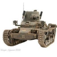
It was really just a stopgap. The Centurion production was lagging behind that of the 20pdr gun, so a new turret was designed to accommodate the gun and it was mounted to surplus Cromwell hulls. It didn't see much service with the British army. -
Just want to say thankyou all once again for taking the time to like and comment on this build, that's great feedback and makes me feel that I am going in the right direction with my model making. Wayne
-
Charioteer FV4101 Medium Gun Tank
diablo rsv replied to diablo rsv's topic in Ready for Inspection - Armour
Many thanks @Kingsman, @Midland1965 and @Reini78, that's great information and feedback. I have duly added the red circle around the triangle. Wayne -
That's looking very good indeed, and now I'm thinking I really need to build a truck. Wayne