


MeneMene
-
Posts
178 -
Joined
-
Last visited
Content Type
Events
Profiles
Forums
Media Demo
Posts posted by MeneMene
-
-
Hello-
I'm working on adding triple ejector racks to the inboard weapon pylon of my F-4. I'm struggling to find good references for how to combine the two parts. Here I have the standard pylon from the 1/48 ZM Kit, and an Eduard Brassin TER.

Should there be any sort of gap between them? Or is the TER flush with the pylon?
This source suggests there's a small gap between but I've been able to find any clear pictures or diagrams.
https://phantomphacts.blogspot.com/2018/10/the-f-4-inboard-pylons.html
Thanks
-
I'm working on a 1/48 Zvezda Mi-24, and have what seems to be a very comprehensive Begemot decal sheet. I'm looking into which version to select. Both of the ukranian options on the sheet are stated to be Mi-24VP, with the 23mm cannon instead of the rotary MG. Looking at wikipedia it seems this was a experimental version of which only 25 were produced.
Unfortunately, current events and news articles have flooded the internet when I try to find reference photos of Ukranian Mi-24, so even with searching the serial numbers given by the sheet I can't find any photographs.
1st Example: Serial # 3532584910287, bort number yellow 6. Stated to be a Mi-24VP with no chaff/flare dispensers. Beige/green over blue camo, white ID bands. Brody Airfield 2014.
2nd Example: Serial # 3532584910259, bort number yellow 9. Brown/green tiger stripe camouflage over blue, with chaff/flair pods. Kalinov airfield 2008. Per the decal sheet, this same aircraft went to Congo for peacekeeping in early 2010, was painted white with UN markings, and in 2014 was also flying combat missions in Donetsk still with the overall white paint and overpainted UN markings.
1) Would anyone be able to help me track down any reference images for these, mostly to establish if they should have the 23mm cannon in the turret or not? I can't find a single picture of a Ukranian Mi-24 with the -VP 23mm turret. All of the pictures of Ukrainian UN Hinds in the Congo are the gunship version with the fixed cannon strapped to the side of the plane, not with the moveable turret. I guess the serial numbers of the two examples on the sheet so it stands to reason they both could be from the limited Mi-24VP production run, but if possible I would like some sort of corroboration.
2) I know many modern operators have repainted their Mi-24 cockpits black for NVG capability. For these Ukranian Hinds circa 2008 - 2014, any leads on if this was the case, or would they be the standard Soviet blue-green. If they have been repainted black I'll need to look for a different version to do as the cockpit's already been finished.
Thanks!
-
21 hours ago, Red Dot said:
I used MRP on a 1/48 F-35 and thought it looked extremely realistic. There is no patchiness visible from the glittery varnish if it is mixed well
Andy
Thank you! I shook the bottle until I saw no more sediment. Maybe I applied it to thick? Do you remember how you sprayed it?
-
I'm building a F-16C Block 42 with a Have Glass scheme, and am working on my approach. First, I have something from MRP, which is a set of two bottles. The first one is the dark grey paint for use as a base, and the second is a coat of varnish that is supposed to go on top to give it the metallic sheen. I've tried it one some scrap styrene here. The varnish does to a nice job of varying the color based on the angle you are looking at it from. However, it does look a little coarse/grainy. This is purely in the pigment, the end result is smooth to the touch. I've seen some up-close images of the real thing and you can indeed see little metal flecks in the paint, but I'm concerned this is going to look to exagerated in 1/48.
I have also seen people suggest mixing a dark grey with Alclad stainless steel and will give that a shot on some test plastic too.
It's very hard to capture it correctly in still images but I believe these demonstrate what I am talking about, the nice difference in shade based on angle and the flecks you can see in the paint. Any tips/feedback? Do you guys think the whole thing would look correct with this approach, or should I aim to go for something a bit more subtle?
-
 1
1
-
-
Thanks everyone. It's frustrating as the detail on the consoles/switches is much better than the kit decals and better than what i could paint by hand- but I just don't see why it's so difficult to match a very well known and standardized color. They'd have been much better off just printing the switch areas and leaving the background transparent. I think I will try to carefully cut these details out with sharp scissors and do it this way.
-
Hello everyone-
I've started working on the new tool F-16C from Kinetic in 1/48. Looks like a nice kit, however I the decals for the cockpit console details looked a bit crude, so I got some of the new Eduard Space 3d printed decals for this area. I'm now having a lot of problems with the color of these and how they relate to the rest of the cockpit.
Everything I've found, and the pictures of real aircraft I can find, are pretty clear that the standard F-16 cockpit color is Dark Gull Grey FS36231. I'm doing a present-day F-16C Block 42 in US service. I understand there are big variations in interpreting shades of grey from photographs, etc. But the base color for these 3D cockpit details just seems way, way too light. I'm used to slightly altering my paint shades to match details like these, but it seems like an entirely different color.
I painted a surface with my Dark Gull Grey, and laid a portion of the 3D decal that I won't use because it features a powered-up display, and the contrast in the colors is jarring. The decal has this very light grey.
In this first picture, I've sprayed what seems to be the correct color on a piece, and here it is next to the decal as a comparison:
And here it is with the test piece applied:
So am I missing some information? Is it accurate to have a US F-16C with such a light grey color to the cockpit? Or am I out of luck and will need to give up and use the kit decals or find some other product?
Thanks for any assistance.
-
On 10/16/2023 at 7:23 PM, Justin S. said:
Hi MeneMene - I use SIMair matt frisket film as my masking material. Once I have the markings cut, I take a piece of cellophane tape and stick it to my skin a few times to remove some of the tackiness, then lay it across the entire length of the mask. I place the mask on the model this way, so that all the components are placed at the same time and in proper alignment. When it's in place, I carefully remove the cellophane tape. It's then just a matter of removing the part of the mask that's covering the area I want to paint, then replacing it before moving on to the next colour. It's a painstakingly slow process, and it rarely comes out perfectly and often requires several touchups.
I sometimes wonder if it's even worth all the trouble! The advantage on this particular plane is that all the yellow parts match because they were all sprayed at the same time with the same mix. If I had used decals, there's a good chance I wouldn't have been able to match their colour very well when I sprayed the cowling, the fuselage band, and the lower wingtips.
I hope that all makes sense - let me know if you need clarification on anything.
Thank you!
So after the entire mask with all the components is positioned on the model, how do you then get the components off without distorting/bending them? And then putting them back on for the next color? This is the tricky part it seems; when doing something like a roundel the smallest error adds up to some wonky circles.
-
Can you share your general technique for doing the masks on the national markings? What masking material? What kind of transfer tape (if any?) For me the biggest problem is getting everything positioned/aligned correctly, especially when dealing with thin outlines like you have.
-
2
-
-
Hello-
I'm working on a P-43, my first time building the type. I've been unable to find much information about the cockpit, just some black/white photographs. Would you paint it with Dark Dull Green like the later P-47, go with the traditional zinc chromate/US interior green, or something else?
Thanks
-
1
-
-
On 2/2/2023 at 3:41 AM, Orso said:
It is what I think in english is called a direction-finding antenna. A pic at the IPMS Stockholm home page.
https://www.ipmsstockholm.se/phpBB3/viewtopic.php?f=2&t=7885&p=63863&hilit=tunnan+antenn#p63863
According to the information there it was used on all versions except the Swedish recce variants. I have read somewhere that it was later replaced when alternatives were developed and that is why some planes have aluminum cover there instead. Johan added the antenna to his model: http://www.ipmsstockholm.se/phpBB3/viewtopic.php?f=3&t=4060&p=33655&hilit=neomega+tunnan#p33655
But there are conflicting informations on which version of Tunnan that used it.
Just to clarify? something. The picture that you referred to is of an Austrian fighter with the recce pod in the nose. It is not a Swedish recce plane.
Thanks for the help. The kit details in this area are a bit simplified, I have a rectangular cutout in the bottom with a somewhat poor fitting transparent insert without any of the internal details represented. I'm modelling a J-29F in 1959. Do you know anything about the timing of the replacement/plating over the section? If that would be accurate for this example i could just paint over it and avoid having to scratchbuild some antenna mechanism on the inside.
-Anders
-
Working on the 1/48 Pilot Replica's J29. It looks like there is a clear part behind the nose wheel. The only good picture I can find on the web of the area is this one:
https://www.cybermodeler.com/aircraft/j-29/pages/bauer_j-29_1599.shtml
The aircraft in this picture is a reconnaissance version, so there are lots of extra camera windows. But I'm talking about the big clear panel behind the nose bay doors, with some sort of cross-like structure behind it. What is this clear panel? Some sort of light? A vision port for the pilot to visually see the lowered nose wheel? Or something else?
-
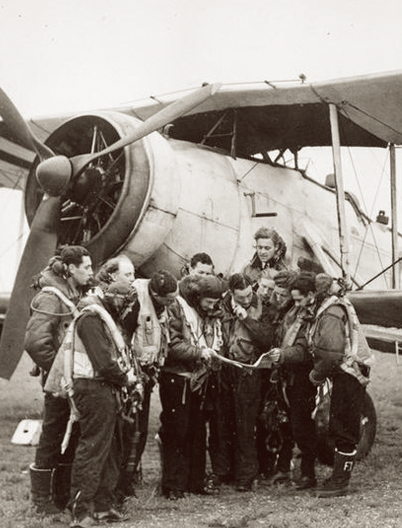
Hopefully it's not too late in your construction process, but I don't believe the engine should have that ring in front of it. I think Tamiya and other companies have inaccurately based that on some modern anti-fire equipment on restored airworthy Swordfish. If you look at period aircraft or other museum birds, they only feature the support struts and not the ring that sits in front of the cylinders.
-
4
-
 1
1
-
-
18 hours ago, Antti_K said:
Hello MeneMene,
the cockpit glazing is the most visible fault. The clear parts are some 1,5 mm too tall. You can see it by looking at the door windows. Remove 1,5 millimeters from the canopy and side windows. Then add 1,5 millimeters on top of the cockpit side walls to keep the side profile correct. Like this:
Another easy problem to fix is the air foil shape. The leading edge is far too blunt and needs to be rounded. I'd say that it is wise to fill the leading edges with Milliput or styrene strips and then start to sand. The wing-fuselage joint is rounded (or "soft"), but that is easily fixed by careful sanding.
The wing chord is some three millimeters too short. Because of that all surface details on the rear fuselage sides are wrongly located. After some head scratching I decided that I will live with the wrong wing chord.
Surface detailing isn't very accurate and the wing under surface detailing is mostly wrong for a P-39Q. I re-scribed all panel lines.
Oh dear. That's a lot of fixes for something I had hoped would be a quick build.
That scribing work is excellent- can I ask what you use for tools/guides?
-
1
-
-
3 hours ago, Antti_K said:
Are you going to correct any of the kit's faults or just building OOB with some added details?
Cheers,
Antti
Thanks for the info!
I'm building the "Bella" combo boxing for Soviet P-39. Comes with the usual Eduard profipack photoetch, but as you said, no metal nose weight. In it's absence, I was thinking of just tracing out and recreating a roof with plastic sheet and cutting a slit in it for the propeller shaft to pass through, if nothing else just to hide all the fishing weights I will need.
What are the major faults of the kit? I've got some resin exhausts and propeller set, but otherwise OOB. Anything glaring that should be corrected?
-
Hello-
Working on the Eduard P-39. The nose wheel bay doesn't appear to have any sort of ceiling, it's just empty space. I would imagine you'd at least be able to see the cannon barrel and some other equipment. I also need some way to hide the mass of nose weight I'll need to prevent tail sitting. Does anyone have any ideas of what sort of structure would be at the top of the wheel bay, or better yet, any reference pics?
Thanks
-
48 minutes ago, Milos Gazdic said:
Hello @MeneMene
Great job!
Sorry for reviving the old post but would you mind telling me from which fret did the seatbelts come and were they pre-painted?
Best,
MilosHello-
I believe it was the Eduard French seat belts PE set
-
I'm working on the Airfix 1/48 Walrus; got a set of aftermarket seat belts. They seem to be representing lap belts without a shoulder harness, but the seem comically large and oversized? Is this really correct? It's the Eduard set.
Any reference photos of the real thing? I've seen interior pics of the one at the FAA museum but that example is missing a ton of internal fittings so I'm not sure i'd fully trust it.
-
Yes. As pictured is the "open" position of the hatch.
23 minutes ago, Kevin Aris said:Yes. This is the open position of the hatch. The hinge points are immediately below the gun
-
I'm working on the 1/350 Hasegawa Mikasa with the lovely Pontos detail set. I've spend the past few months carefully setting up the walkway and booms that hold the torpedo net. I plan to have the net stowed, so the booms are folded against the hull.
I'm planning on recreating the rolled up net with a folded/rolled length of nylon tights. The thing I'm not sure of is what sort of diameter the net is supposed to have.
The problem I'm running into is that the 6 inch battery guns have a hatch that falls out and rests against the torpedo net walkway like so:
This doesn't leave much space for the net to pass underneath it.
Would the rolled up net be small enough to fit in that space? Phrased differently, should I make things work so that I glue the hatches so that they fold all the way down to touch the walkway, or would the hatches be resting on top of the torpedo net and leave a gap?
-
3
-
-
15 hours ago, JWM said:
It is if green/black as you painted, not as is shown on box art
")
Any problems with kit? I am very close to do it also...
Regards
J-W
Main issue was some rough/grainy texture of the plastic in certain areas. Easily fixable with some sanding but still a bit annoying. I also had the same thing on the Zvezda Pe-2. The kit lacks some major detail around the lower bomb-aiming windows; there should be some internal structure/ribbing visible through them, I think they were integrated into the flaps. Wasn't aware of that at the time (sources for this aircraft are difficult to obtain in English), so my representation of that area is a bit crude and simplistic. Other than that, the kit was pretty straightforward. I did put in a lot of the work and time into some resin corrections (Vector wheel well + engine/cowling) which made the kit considerably more difficult, but OOB I don't anticipate you having many problems).
-
1
-
-
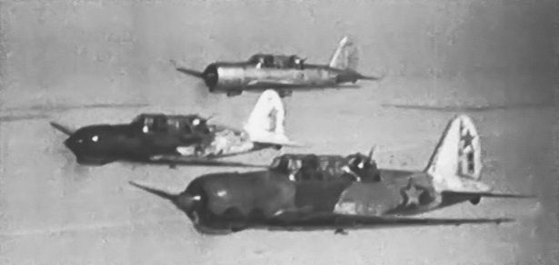
16 hours ago, Dimmy said:
I found only this frame:
Thank you!!
-
Hello- I'm working on Zvezda's Su-2. I'm depicting an aircraft that from profiles is stated as Serial # 070105 of the 43rd Bomber Air Regiment in the winter of 41-42.
I've only been able to find color/profiles. The decal instructions that I have for this example show the whitewash to be limited to the rear/fuselage and tail, extending somewhat onto the wing roots. However, several other builds I've seen of the same plane, and some artwork, has showed the whitewash also applied to the rear of the wings.
Does anyone have guidance on which way I should go, or better yet a photo of the actual aircraft in question?
Thanks in advance for any assistance
-
So I've been wading through what research I can find and the multiple forum and blog posts by Nick Millman/Aviation of Japan, and have been getting progressively more confused. I'm working on a B6N and have been struggling to get the upper green looking right, and am puzzled as to what to use on the underside. I made a color swatch from the paints I had and scanned it:
1) Upper surfaces: D1 vs D2 green; from what I gather, XF-11 is meant to represent D1(the darker of the two), and XF-70 is meant to represent D2. Now, which to use? Some paint manufacturers/online posts say nakajima used one, mitsubishi used the other, some say they were more interchangable?
Here is my initial attempt, using primarily the Gunze C-15. I'm not entirely happy with it, I think it looks too green. Some of that comes from some very diluted lighter paints I put on to give some color variation; super dark colors are hard to make convincing. Would a B6N likely be more like D1 or D2, or is it a purely academic question? Any suggestions for the color? I could make it darker by going over it with some of the XF-11/D1
2) Underside: I gather this is supposed to be J3 grey? I've seen this as being a almost neutral grey like the C53 in my color scan, to a pistaschio green like C128. The instructions recommend gunze C56, and this is a very green gray. I don't have it, but I can get it, looks pretty close to the C128 I do have.
The only other model in these colors is a Nakajima-built A6M5 that I tried to represent as relatively new and unfaded:
I think I used base colors of XF-11 over C53 grey. Based on what I've found now, I believe the gray is too gray and not enough green. Would this and the B6N have had the same underside color, or was there variation between the above grey green to the more neutral green I have?
3) Any suggestions on what the other colors are supposed to represent? XF-76 is what I've been using to represent early war ash-grey Zero overall color. Not sure what the difference is between Dark Green (Nakajima) C129 and IJN Green (Nakajima) C15 in the Mr Color range. XF-12 might be trying to represent the underside J3? Maybe C128 is meant to also be the overall ash-grey early Zero color, or maybe the similar army paint used overall on Ki-27?
-
4 hours ago, KelT said:
The three bracing rods are found on all aircraft but the outer ring and it's three triangular standoffs are found on very few indeed. I haven't been able to find it on any MkII's and only a few MkI's. Normally it is painted black but from the second image it's obviously stainless tube, there is the one fitting at about 4 o'clock and a second fitting at about 10 o'clock. All I could think of was that it may have been a post production, in the field, temporary fix for an oil heating problem just prior to the larger cooler being added? Or perhaps it was added only to aircraft operating in certain areas at higher temperatures, that is if my suspicion about simple oil cooling is correct.
As far as I'm aware, the ring you see in front of the engine in current day Swordfish (which is inaccurately copied onto model kits) is part of the modern fire extinguishing system. The ring should be removed for a WW2 Swordfish.
-
2
-


F-4 Phantom LAU-17 + TER mounting
in Aircraft Cold War
Posted
Thanks all!