


greggles.w
-
Posts
958 -
Joined
-
Last visited
Content Type
Events
Profiles
Forums
Media Demo
Everything posted by greggles.w
-
Thanks Joachim, yes screw can cause damage - has roughed up sanding stick that got too close! So I have knocked the edges of things .. cowling now has a curved nose. I find this compound curve work very challenging! Took me some time to gingerly sand it down, I have something of a lingering one-eye-closed squint from constantly checking & re-checking as I went along. Once the sharp edges start to dissolve, then what does one use as reference? Add to that the need to deliver symmetry! Well it reached that point where I can recognise it’s not a perfect duplicate, it is about as good as I’ll get it & I sense that any further fiddling & I’ll stuff it up .. .. very hard to photograph too .. the buttery unpolished timber absorbs light & flattens everything out .. .. there’s a smidgen of fat in the diameter behind the screw, allowance to blend to the prop & spinner when the time comes. Only one more woodworking task remains, for which I first need catch my breath: the longitudinal concave pinched waist to the canopy.
- 107 replies
-
- 11
-

-
A very, very reasonable question! I have been telling myself I’m only scratchbuilding the bit between the ‘V’ which will be visible through the open mouth under the prop .. maybe I’ve made a little bit more than will be needed .. 😄
-
Hello, nice to hear from you & thanks for your kind words Adrian. Now you draw that parallel to those other Italian tails I can't not see it! Perhaps I ought to have started with a crisp high-spec kit of one of those less obscure machines!? Quite so, many parallels: wooden construction, high prop alignment due to inverted engine, wide-set undercarriage, racing pedigree ... (your polish example looks very handsome!)
-
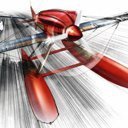
Hurrah, Ian, nice to hear from you! So, yes, funny you should say that re the '108. I went hunting for information on the Hirth & quickly turned up a reference to it being installed on the Messerschmitt Taifun. "Excellent!" methinks, as I have Eduards 1:48 with air-racer markings in my stash, and I can scratch something of a duplicate with reference to that. And so off I went with my callipers to measure & then to work with sheet styrene & brass .. .. made myself some cylinders, block, gearbox, pushrod sleeves, rockers ... and feeling chuffed with myself for sourcing all that from scraps & supplies at hand. BUT .. a niggling feeling was a-brewing .. the proportions seemed a bit wrong, the dimensions seemed at odds with those I was interpolating for the cowling, the bottom in particular seemed overly wide ... Well, it just so happens that, yes, the Hirth 508D was fitted to the Bf-108 .. but only the first few pre-production examples that is!! Thereafter, as you rightly say Ian, the hundreds subsequently built were fitted with the Argus!! Arrrrrgh(us)!! Both motors are V8s, both inverted, both air-cooled, but the Argus I had been faithfully replicating is a 90° V whereas the Hirth is a tighter 60° V. A problem of my creating, so it falls to me to fix it! Well after some more research - more thorough research - I decided it was possible to salvage something of the effort invested to date. I just need to break the back of it ... ... & re-set things in traction ... a jig perhaps @Courageous? The cylinder banks were near enough for my purposes, and I'd be happy to leave them alone, with much simpler edits to fill the wedge in the dumb-lump of engine block & then reshape it. And so here it is below as it stands now with replacement approximation of gearbox. I'm pinching it together in this image - I decided having the thing split down the middle would be quite helpful when I detail up between the 'V' with pushrods & the like (remembering that the principle view of this will be limited to that through the cowling 'mouth'). Painting is slowly progressing ...
- 107 replies
-
- 11
-
-
Oh! I forgot your last query. For this there were no drawings, so it was a bit of proportional analysis of photographs .. so I say they are much closer to the 'truth' than the kit configuration ... but it's your risk if you choose to land on them!
-
Another familiar & friendly fellow! Hello Stuart! Re jigs - yes, a predisposition of mine! More to come I'm sure 😉 Regarding the reasoning for construction sequence, in summary it's a need to have 'the known' elements stably constructed as reference from which to launch the various scratchbuilt bits. With the wing roots in particular, the front extension of these forms a critical geometric setout point for the apex of the rear cowling vent, so they had to come first ...
-
Thanks Malc, it's nice to see familiar folks pop up & for you to be welcoming despite my absence! I've been mulling this over & I think it was one image that popped up one day in a F'book feed* from a French fellow who posts one such obscure aircraft every day or so (I think?). It caught my eye straight away & sent me on the same relatively fruitless search as you on the web. I've slowly accumulated references over time from various places. Image search on F'book. I've found putting the aircraft name in as a saved search on eBay can often yield surprising results in unexpected formats - the artworks showing this machine are from postcard sales. And for this one I posted some hopeful requests on Italian historical aircraft F'book groups, with some very generous people helping me out. One thing which made this particular machine harder to find is the designation. It took me a while to understand that there's an SAI.7 & there's a SAI S.7 - the former being this racer & the latter the post-war military trainer. Images are named either on the web (and other variations besides!). Quite confusing. My benchmark is the Ali D'Italia book I show above - all books in this series seem very thorough & reliable. * the F'book feed is called (deep breath) "Avions moches, bizarres, rates, projets abondonnes et aviation insolite" EDIT: I forgot to say, one more compelling reason why the existence of this machine was overlooked - it was flying mid 1939, setting the speed record at the end of August 1939 .. the world had other things on its mind in August 1939!!
-
I should say first Mark that I'm still quite new & tentative with this scribing thing, it wasn't part of my childhood experience of the hobby! So that likely informs my tool selection. For the most part I use a sewing needle in pin vise first, then switch over to a scribing tool by RB Productions called 'Scribe-R'. It comes as a little kit of etched stainless steel which you fold & assemble then fit into an Exacto handle. It has proven reliable, predictable, even if my skill using it is less so!
-
Thank you all for the comments & queries - a nice welcome back to the keyboard. I want to respond to each, but first here's another update on the timberworks which will bring the story of that portion of the works up to the present day ... The nose is a geometrical challenge! It needs negotiate from a rounded-off triangle at the back to the offset perfect circle at the spinner, retaining the continuous sweep of the spine arc and more besides .. In thinking this through I came to the conclusion that generally I'd be happy if the form approximates that complexity, but if the circle upfront wasn't circular, then that would be a glaring error. I also know it would be just-oh-so-easy to ruin that circle with a sloppy pass of a needle file or sanding stick, so I must find a way to protect that circle! After hunting through my hardware odds 'n ends, hoping for a suitably sized metal washer (none such to be found) I arrived at this! Interestingly screw heads are not as industrially uniform as you might expect! I went through quite a few in my circle template until I found one which was actually circular. It's a Phillips head screw .. I filled the X on the head with epoxy & embedded a 1mm brass rod, drilled a slightly oversize hole in the timber, then used fiddly bits of double-sided tape at front & a tiny drop of CA glue at back to fix it in position. And so the same process again, selectively addressing a particular face one after the other: first the reverse curves of the chin, then lop of the angled cheeks, start merging the bridge of the nose into the canopy arc ... .. as the surfaces came to meet the cowl & canopy behind it was essential things stayed in position, so the nose upgraded from double-sided tape to a wood-glue bond (the nose & cowl will be the one vac draw). Thereafter it was careful incremental work to blend together ... So that's where it stands as of today. This finalises what I understand to be the primary faces of the nose. From here there's a lot of rounding-off to round this out. All the sharp surface junctions around the front face will have more or lesser rounding out. The jowl line from the bottom of nose & along the cowl needs a tight radius arris to meet the wing root extensions. For next time ...
- 107 replies
-
- 14
-
-
Thanks for the welcome back Matt! Here's some more as requested: The main event. Canopy & cowling. The former obviously needs be transparent & hollow, while the cowl needs be hollow too in order to house the motor. So both require vacformed parts. To get there I first need to carve the bucks, so here we go with basswood blocks + removable-adhesive paper templates. This looks like three, but is actually two. The upper canopy buck is two-part with a sliver of cedar veneer in the middle, the cedar having ben pre-cut to the cross-section profile to guide sanding to shape later. Below shows the same in profile. Unfortunately I had not recognised that along with the obvious re-profile required for the canopy, there will also need be a subtle bulking-up of the fuselage spine behind the canopy to smoothly continue the curve. To this end a styrene backbone has been glued on as guide for future putty work. So with some confidence that those guide lines seem to be leading me in the right direction it's time to cut, peel, whittle & sand away to extract the desired shape from the timber blocks. I do this in a series of moves, selectively slicing along a guideline, then peel off part of the adhesive paper, whittle the approximate form & then sand down to meet the guide ... ... sometimes I then affix another adhesive paper guide to the exposed face, or other times draft directly onto the timber ... ... progressively the form transitions from planar to curved, it's like taking the training wheels off the bike! I know I could never get to this outcome if I tried to go direct to the final form. At this stage as the guides are falling away I'm a little more cautious too, stopping a little +X% extra short of the guide, so that there's some float for when I merge with the next adjoining part .. Generally heading in the right direction methinks! These parts were complex enough, however it's the next part - the cowling nose - which will be the real test ...
- 107 replies
-
- 16
-
-
Before addressing the major task of replacing that which was sawn off, a few tasks to attend to on the belly .. First, blanking off the wheel wells for in-flight display. Not such a simple task, partly as the configuration of undercarriage doors changed markedly from civil to later military variants, and partly as the kit wheel wells are of questionable accuracy for any variant I suspect & definitely asymmetrical! From left to right below: transfer film used to capture the outline of the openings as supplied; that film then used to mark shapes onto thick styrene card to shove into the openings; the blanking sheet then sanded flush to aerofoil profile & corrected doors scribed. Also left to right above: a parallel necessary task, fleshing out the belly profile & wing root leading edge extensions to meet the new engine firewall. The latter have a quite pronounced form, so to give an edge which would be both definitive to shape to & robust enough to resist accidental damage, I epoxied in little lengths of 1mm brass rod. These were then progressively embedded in the putty build up, and then the used as a guide to sand back to. With that done, the surrounding panel lines were scribed, and the underside declared done (until later primer coats tell me otherwise!!) Ready to go back topsides ...
- 107 replies
-
- 11
-
-
Surgery with a razor saw ... ... and some more ... Done!
-
So into construction! First task: join fuselage to wing. A basic task surely!? Not so. The adjoining faces & edges would not coordinate for reference, so much so that I lacked confidence about any bringing these parts together in anything close to alignment. So a jig was fabricated ... The upper wing-root fairings are integral with the fuselage parts ... but they were rubbish with wobbly edges. So much so that I had to use the jig to reset the receiving edges of the wing, I had to carve out large chunks of resin which were grossly misshaped, and then introduce various thickness of shim to bring the two to meet. The wing-root fairing was metal fixed over the wooden skin, so I used Dymo tape as a guide when sanding back the shims so they will sit ever-so-slightly raised above the adjacent surface. (That image also shows my re-scribed wing panel lines) Once that was done, the resulting trenches were slathered with epoxy putty ... ... and then with Dymo tape protection either side, the concave shape was sanded back ... So with the straightforward task of joining the primary airframe together done, the measuring & marking could be done, ready for the butcher's knife!!
-
Thanks for saying hello Stuart, nice to hear from you. Sigh, I'm afraid a run of serious health concerns afflicted my family, requiring a rapid pivot to caring role, a withdrawal from work & all the cares & concerns that entails. Now things are at least a little settled in their new madness there came a chance to reengage with the hobby. Stepping straight back into projects delayed felt too much of a reminder of all the disruption, so instead I've gone for foolhardy optimism & started something afresh! I'm overdue to reengage with the good work of others on here - an overwhelming number of red notifications to sift through! Again, thanks for the hello, hope to be present for as long as circumstances allow.
-
With the kit now presented, here now a little more of the plane. First some overall views, in varying markings, though all I believe are red! With this one - racing number [42] - being the one I'm working toward .. That sweeping arc along the fuselage spine & canopy is so stylishly distinctive! In detail too the canopy is quite unique, with framing, openings & 'pinched' cross-section all interesting .. not least as I will need to be fabricating this from scratch! My preference for display in-flight thankfully negates the extra challenge of that opened canopy! Powerplant for this Italian racer was a German air-cooled, inverted V-8 Hirth 508D, tightly packed in there .. Again, in-flight display keeps those cowling panels on, saving me the trouble of replicating that complexity! That said, as it is an air-cooled engine with no frontal radiator, there will be need to mock-up something mechanical to be seen through the openings in the cowling nose ... Finally, here's a view of the general mode of construction. The run of variants & derivatives of this design continued on into the post-war era as a trainer for the Italian Air Force. This is one of these showing the timber construction common to all variants, with the resulting smooth finish largely free of panel line & rivet detail. OK, so that seems like sufficient introduction. For those further interested in the type, there's this bi-lingual reference book .. if you can find it! I have a phone-scan thanks to a helpful enthusiast on an Italian F'book page, but have yet to source a hard copy (anyone have one gathering dust on a shelf?).
-
It is a very stylish machine, hard to resist .. all credit to the designer! Yes .. well observed Mark .. says I with 'benefit' of hindsight! Here's the humble little kit. That's a folded & stapled paper lid to the box! Contents being creamy yellow resin, a one-piece wing & fuselage halves plus various bits 'n pieces, together with white metal undercarriage legs, a little sheet of styrene scribed with undercarriage doors, and a clear vacform canopy (not shown): From all that I believe I will be using the flying surfaces, fuselage, and .. well, given I shall display in-flight, that's about it I think! This image shows the general standard of resin casting. There's not a lot of surface detail, which it should be said is appropriate for the relatively smooth timber construction of the real plane. However some of the detail has an overly smooth, almost 'plump' character, bulging out a little either side of panel lines ... Sufficient to make a start on ...
-
.. hello? Here follows my latest .. and I thank you all in advance for not mentioning my numerous other unfinished WIP projects!! Ambrosini SAI.7 racer. 1939 IV Raduno Aero del Littorio 1939 FAI World Speed Record 302.58km/h (Category C, Powered, Multiseats, 6.5 - 9L, 100km closed circuit, no payload) The interwar racing predecessor of the SAI.207 lightweight fighter of WWII. So this will be a conversion, backdating LF Models resin SAI.207 (long-nose, single seat fighter) to the red racer (short-nose, tandem seat). Work has progressed enough that I thought I may now have something of substance to share. More to follow soon ...
- 107 replies
-
- 15
-
-
1/32 Short Bristow Crusader - finished!
greggles.w replied to Malc2's topic in Work in Progress - Aircraft
Unfortunately circumstance has enforced a protracted absence from this civilised forum. An opportunity presented, so I thought I’d see what builds might be underway .. Well, this is just a marvellous discovery! So pleased to see this machine receiving such attention. Great techniques & component breakdown. This is a rare treat to see another address the same challenges, but in a cleverly differing innovative ways. Boy do I wish I had known about those serial letter decals!! Thanks for going to such extraordinary effort to hook me back into things here 😉 Will be returning to see this as the finely crafted completion it is on the path to be!- 100 replies
-
- 1
-

-
- scratchbuilt
- Schneider Trophy
- (and 1 more)
-
Auster Autocar goes to the Antipodes
greggles.w replied to greggles.w's topic in Work in Progress - Aircraft
Flat out busy days in succession, little progress, but offset by receipt of a parcel in the post today - a custom timber plinth by Jim’s Bases in Queensland … Lovely recycled hardwood, made to my specs with intent to hold the airframe at in-flight attitude. -
Another stylish machine, progressing rapidly!
-
OK, OK, now I understand Stuart! I thought one must be in desperate straits if contacting me for advice … now I can see what a challenge you have landed with this Merlin kit!! It’s a lot rougher than the LDM offering I was working with. Nevertheless you’re making headway, & I’m sure on completion you’ll be awarded full membership of the UK Guild of Blacksmiths. One more bit of extra detail I neglected to confirm yesterday: the specific epoxy I used for critical structural joints was ‘Selleys Araldite Ultra Clear’. Note that this was not arrived at after a comprehensive testing of all the market options .. it’s just one I had on hand & happily it worked. Also note that it takes quite some time to cure .. up to 16hrs for maximum strength. This wasn’t so much of an issue for me as the intervals between leave-tickets for bench time are quite extended for me .. but at your pace here that may not suit. Following along!
- 54 replies
-
- 2
-
-
- 1/72
- Merlin Models
- (and 1 more)
-
This is a very stylish machine, sleek & purposeful. Rapid progress Stuart, looking good!
-
Auster Autocar goes to the Antipodes
greggles.w replied to greggles.w's topic in Work in Progress - Aircraft
Hi & thanks Malc. This was a concern of mine before use. I can report it was quite benign - as Ian predicted - in two regards: - one, despite the riotous chemical stench, it didn’t dissolve either the sheet styrene nor the joints; & - two, during application it had a consistency something like toothpaste, which meant I didn’t need to use force to spread it over & in-between the styrene frame, so limiting the risk of breaking something. It did bond very well to the styrene. There’s a few areas where I subsequently sanded back the filler to such a thin layer it was a mere translucent film … but that film is solidly fixed in place. Main reasons: - just a small area, whereas the auto filler is all ‘big’ - big tin, big tube, big quantity mixing - and so more suited to big tasks. - I was tinkering late at night, inside, so the odourless yellow Tamiya epoxy putty (quick type) was best. The intense stink of the auto filler had me applying it while wearing a full gas mask, outside, on a sunny day! -
Auster Autocar goes to the Antipodes
greggles.w replied to greggles.w's topic in Work in Progress - Aircraft
Thanks Adrian, trying to keep in front by a nose … I had an opportunity to drag out the ‘old faithful’ vacuum & commandeer the kitchen. Here’s the first draw over the nose .. optimistically propped nose skyward, hoping for a one-piece outcome … Hmm, me thought. Some 'banyan' buttress webbing (as should reasonably be expected). The buck was lodged in there, and time was limited, so everything had to be put aside. My initial thought being that when I could get back to it, I'd cut the buck free & then need concentrate on an altered balsa plinth, perhaps higher, perhaps wider .. So several days later, in need of a non-stinky task, I started to trim back the excess to extract the buck. And to my pleasant surprise the plastic looked recoverable! Those webs had fused together, such that when trimmed flush they left only the most minor trace - less than when I get heavy handed with a sanding stick. So, with the buck still lodged inside (for strength in handling & for it’s still useful guide line work) first task was to ‘sharpen’ the protruding vents / scoops … The lower one shows the raw blobish shape as start .. the top one there has had the form sharpened with needle files. Next scribe the side panel lines, then glued on the kit cowl face .. .. all fine (if a little roughly finished!), other than the evident fact that I grossly overcompensated for plastic thickness! The timber buck had been nicely flush with the top of the grey cowl face, whereas now I have the step as seen on the ridge above. So clearly I took far too much off the timber. So needed to putty that. Here's status, with the cowl (+ buck still inside) temporarily cantilevered with double sided tape. Looking like an Autocar! -
Auster Autocar goes to the Antipodes
greggles.w replied to greggles.w's topic in Work in Progress - Aircraft
Thanks Ian, & re the Sword kit you’ve reminded me … I have been intending to state clearly that the limited use of Sword kit parts should not be seen as a poor reflection on the kit. As I work my way around the airframe I am constantly cross-comparing the Autocar to MkIII, benchmarking changes needed. As part of this process I also then need just confirm that the kit MkIII matches the baseline reference drawing MkIII .. and every time it’s been spot on. From the overall dimensions like wingspan down to the details like fabric tape banding count & spacing etc. If one were looking to build a MkIII Auster I can say you’d have a very enjoyable straightforward time with the Sword kit & can be confident you’d arrive at a true likeness!
