


TheBaron
-
Posts
7,525 -
Joined
-
Last visited
-
Days Won
54
Content Type
Events
Profiles
Forums
Media Demo
Posts posted by TheBaron
-
-
13 minutes ago, Austin 7 model said:
Thanks for this Tony. It must have taken you ages to put together. I have had some success with cast parts in aluminium, and just as many failures, but I haven't tried vacuum casting usin ivestment. I will bookmark this page for future reference.
Thanks again, Lee
Glad it was of some encouragement Lee!
After the first flush of success as it were, over time I came to find the amount of work it took constantly tending the above arrangement to get 'good' i.e., usable for modelling purposes overly time-consuming, so took the plunge late last summer and invested (no pun intended
 ) in a proper burnout kiln for the studio. Now it just works away in the background whilst I'm doing other things and rarely a fail.
I got mine from Tuffnell Glass over in Yorkshire; Martin there is a very nice guy to deal with.
Best,
Tony
-
On 14/02/2024 at 18:06, Billy54 said:
I was attracted to the book by the word "Jazz" in the title and had visions of hopped up jazz musicians and sultry torchlight singers performing in smoke filled clubs and speakeasys to a audience of flappers, playboys, drug dealers, pimps and other undesirables but I was disappointed because none of that happened.
😂
As his agent might say: 'Mr. Spufford is not known for that type of writing...'
-
 1
1
-
-
If you're one of those interested about questions of the 'why' and 'how' behind
aviation and naval subjects at particular points in history, a couple of tomes have recently been rewarding to alternate between.
Part of that larger story about the uses of operational research in the last century, this one obviously focuses on how it was taken up as a way of identifying and thinking through problems in an aerial context:

You can access a copy here free of charge.
This one:
- looks at those factors largely absent from standard military histories: the nature and attitudes of the society producing such craft, in terms of how both have evolved co-independently over time.
-
 1
1
-
-
Mike: I used to use the paid version of Lychee due to finding the support design process superior to Chitubox, yet could never get its antialiasing function to work satisfactorily with Elegoo printers. Having switched to using Voxedance's Tango (VDT) back in October, I find it's support design process far more advanced and rapid to use than that of either Lychee or Chitubox.
Hth,
TonY
-
 1
1
-
-
On 29/12/2023 at 10:48, wellsprop said:
Can anyone give me some tips?
Ben: I'm (imminently) facing a similar issue but would agree with Eb's post here as the route to go:
On 29/12/2023 at 21:12, Ebf2k said:I am not sure how they do it, but probably with a different 3D modeling tool like Blender to apply a surface to the geometry. Something like this perhaps.
CAD software by it's nature doesn't handle the more organic natural textures so in my case I'll export the shape(s) concerned into Maya as an .obj file and apply displacement mapping to created raised textures on the polygonal geometry there, before outputting as .stl for print.
There'sa summary here about displacement mapping in Maya that applies in general to all CG packages with this function.
Best,
Tony
-
2
-
-
Sir: I came here to admire the big sausages only to have a general's balls shoved in my face. I wish to complain in the strongest possible terms about such juvenile reproductive humour.
Yours &etc.
Jenny Tailor
-
6
-
-
On 31/01/2024 at 15:56, Pete in Lincs said:
And now what it's all about.
As long as both parties are enjoying themselves that's all that matters.
-
6
-
-
On 28/01/2024 at 19:12, hendie said:
come to think of it, the color isn't too far off. It works for me.
We know you calibrated that colour carefully to account for the visual effects of viewing it in Earth's atmosphere compared to the composition of Altair IV's Alan....
-
5
-
-
An absolutely compelling body of work Mike and one that does great credit to Pete's designs. Those really feel like scale replicas rather than a 'model of', if that makes sense?
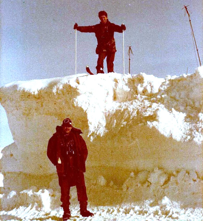
On 09/12/2023 at 20:12, bootneck said:If anyone is wondering where one might find square snow mounds with a deep undercut, as in my diorama, then the answer is Norway.
I wondered why you posted a still from the advert....
-
1
-
1
-
-
Very nice progress Ian - I love returning to this thread each time to see the kit and your own designs in symbiosis. Bravo!
-
1
-
-
Really enjoying the development of your designs into physical reality Sebastien.
-
1
-
-
Solidarity and empathy headed your way Bill.
'Damn life', as John Cale puts it....
-
2
-
-
Morning all <flexes knees>
I'm pleased to say that recent efforts have seen (barring the AS.12 installation) the exterior designs for the Wasp now completed.
Answerphone messages first though as usual:
On 13/01/2024 at 16:47, perdu said:I like the idea of slotting the kick panel windows into a fixed location, I suppose then you might be able to add the fixing screws afterwards, the damned things are making me wake up with another yet approach to try next...
One of those parts that looks superficially easy until you get your hands on it isn't it Bill? There's a nice view of the panel in isolation here:
https://www.ebay.ie/itm/305368614587
As it's all a single and rather thin unit I've had to include the strip around the transparency in the vacform design so if the screws on it look naff, I'll file them of and reinstate manually.
Your miniature of it looks excellent btw!
 On 13/01/2024 at 18:09, Serkan Sen said:
Although the Blackbird and Oxcart clear parts are significantly smaller than Wasp I wasn't able to get clear parts printed nicely. I have used several clear 3d resin products without having an acceptable success.After printing the parts I soaked the parts in Future or clear epoxy resin, sprayed parts over with 2K clear coat, sanded the surfaces with 3k to 12k grit polishing papers, polished them with Tamiya polishing compounds. Each method has some pros and cons but none of them was perfect.
In terms of the amount of effort required to achieve an acceptable appearance it's still a frustrating process isn't it Serkan? 3D printing is kind of 90% of the way there for transparencies at present but there remains that final gulf which it is incapable of bridging for the kind of work we do.
On 13/01/2024 at 19:49, bigbadbadge said:Crikey, I have missed seeing those fantastic renderings, great work as usual Tony, it sll looks superb .
Ta Chris. Things seemed to spend ages recently stuck at that frustrating point of finding lots of exterior details I'd overlooked/ignored until now but thankfully the items have been ticked off the list in recent weeks.
On 14/01/2024 at 07:25, giemme said:Amazing ypdate, as usual
I like that typo Giorgio and may modify it as a 'yepdate' to indicate when reporting on something going well!
 On 14/01/2024 at 07:59, keefr22 said:
that CAD artwork would look good on any wall
Sending the stencil to Banksy as we speak Keith....
On 14/01/2024 at 14:44, hendie said:If you ever get around to doing a 1/24 Wessex, just make sure it's an HC2

Help!
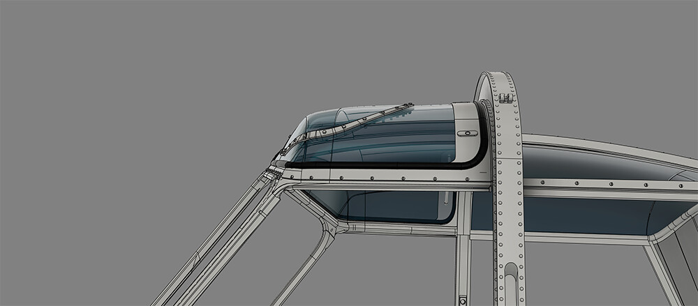
Still the cockpit interiors and APX sight to do of course but what follows is a visual summary showing the final stages of detailing the exterior of the vehicle.
With the roof and nose areas done, the remaining areas to be filled in were the sides and undersides of the cabin section that sits between the engine deck and nose unit. In such cases it always makes sense to handle all the symmetrical details first on one side - as I've done here with the starboard features - so that once done, they can be mirrored across to port for any asymmetric additions to be made:
Tucked away on the mid section just forward of the jury beam on either side are the diminutive and slightly odd-shaped navigation lights:
In contrast to the large areas of transparency (where it didn't work), such small transparent details as these will be a good candidate for printing using AC's High Clear resin, due the small surface area requiring polishing up. With those small lights done, it was then on to the downward identification and larger landing light on the underside beneath the nose:
Yes there are lightbulbs in there under the lenses - these should just print from AC HC at 1/24, though I'm less sure about 1/32 but will try anyway. In homage to the classic Airfix method of mounting undercarriage legs, I added a substantial mounting pivot for the landing light so it can swivel downward like the real thing:
Directly in front of the fairing for those lights sit these two rectangular transparent amber light-like fittings:
As one of a series of such puzzles on this build, I had to scour the maintenance manuals in order cross-reference parts numbers from drawings to - I think (though open to correction as always) - discover their purpose:
The honeycombed nature of these RADALT fairings should also lend themselves to reproduction with Anycubic's High Clear stuff.
A couple of rendered views to summarize progress at that point:
There is quite a lot of detail on the central section of the underside that is not straightforward to discern due to the maintenance drawings being largely oblique views, and with the same issue overlaid by wide-angle lens distortions in photographic references. However, in being blessed with both @bootneck's and @Anthony in NZs source imagery for this region, I've managed to minimize inaccuracies of shape and disposition as far as possible from such material.
As the torpedo/bomb carriers themselves provided a valuable central datum to begin work, I used their position to rough out as always a sketch map of the required topography:
In examining the various images I had of the torpedo release gear, many of them were close-ups without surrounding context to identify what side and angle they were taken from, whilst more distant contextual airframe shots didn't show enough detail (either due to distance or shadow) to act as confirmation. For a period then I was confused that I was looking at two different variants of the release gear as they looked so different. The PN's however were clear (without reference to any subsequent Mods) that in the case of both the Mk.44 & 46 torpedo layout, the EM/EF 100/1000 carrier was preferred method for upsetting submarines:
Interestingly enough, the Weapon Stations loadout diagram preceding this makes it clear that aside from the capability to carry Mk.44s on both sides, a sole Mk.46 was only carried to Stbd.
By cross-referencing source images I was able to confirm that the contradiction in features on closeups of this gear resulted purely from their being a different arrangement of details on either side of each carrier, a fact finally nailed down by locating identical ID plates on two different sets of images:
The visual giveaway on more distant shots are the lighter features which stand out (once you understand the close-up details); the prominent silver cylindrical fuzing unit to the rear of the stbd side of the carrier, with the long rectangular ID plate on the port side indicating that aspect.
Stbd:
Port:
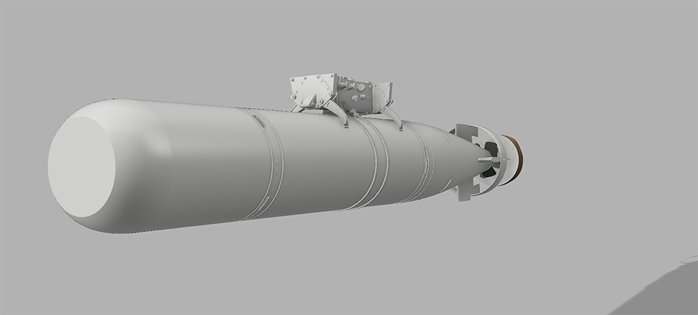
It then occurred to me that the torpedoes themselves make for an additionally useful scale/position reference for surrounding features, so I spent a week down the torpedo rabbit hole as it were, firstly on the Mk.44:
For print purposes this was divided into warhead/fuel-tank/afterbody/propellors (x2) and parachute bag sections. A centering channel down the middle for brass rod helps everything align along the longitudinal axis during assembly, with a similar side channel to line the sections up laterally:
This process was then repeated for the Mk.46. Whilst their diameters are the same, the 46 is longer than the 44, with different propellor, parachute and guidance features, as well as different port/surface features:
At the rear, the prominent battery unit and fire control sockets are visually similar, and, as far as the RN/RNZN are concerned, the same Type-C suspension bands were used for both variants:
Again on the Mk.46, the same kind of alignment channels are used for assembling the parts correctly. In terms of fixing the torpedo(es) to their carrier, the release hook of the real thing obviously wouldn't be strong enough in itself to suspend either torpedo body so in order to make mounting them in place as strong yet unobtrusive as possible, a brass pin is used to pierce both carrier and torpedo in a manner that should be largely invisible to the eye when assembled.
The sway braces themselves will also be glued into place along the fuel tank for added strength.
A Mk.44 and carrier combined:
Both variants compared:
With those prominent items as landmarks, I could then start filling in the various small fittings and fuzing units &etc. underneath the cabin:
I must confess to a considerable amount of eyestrain in having to redraft several of those features until they resembled more closely what photography revealed.
I call this feature a 'step' only because it resembles one but as it's only present to port, that can't be it's real function:
In the realms of wider speculation I briefly considered that this might be a parachute mounting for the diagonally-slung WE.177, but can't see that as the case:
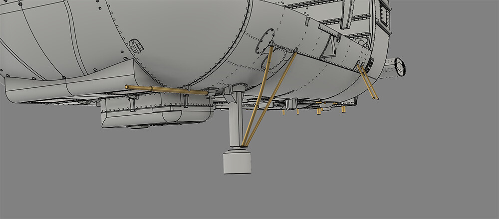
Up front beside the landing light fairing is the 'coffee-can' shape of the I-band transponder, with the pitot inboard of it:
The front diagonal brace of that transponder seems to have an odd 'kink' in it:
I thought my images just showed the same damaged one but this seems present on multiple airframes. I wonder is that so that it follows the contour of the airframe when the transponder is in stowed position?
With carriers fitted:
- and a Mk.44 along for the ride:
Renders to finish:
I need to stop staring at rivets for a while. Am currently addicted to Le Bureau des légendes after getting withdrawl symptoms from Slow Horses....
Hoping this finds you well,

Tony
-
18
-
1
-
-
11 hours ago, Terry1954 said:
Perhaps Tony @TheBaron
Coincidentally there's a new distillery opened up 10 mins down the road from me. Actually, given the contemporary growth in distilling here, there must be a national Uisce Beatha Plan to ensure that no citizen is ever further than 10 minutes from a source of whiskey.
-
7
-
-
Alan I must confess I thought you'd stopped building for a while until popping on to your profile to find this utterly beguiling project under way. You know my admiration for your work so please accept the usual superlatives as a given.
You mentioned about maybe using clear resin but worried about yellowing? I can confirm that I recently tested a part done in Anycubic's High Clear stuff for yellowing and having left it in daylight for six weeks on the studio windowsill, no trace of jaundice that I could see.
-
5
-
-
HNY to you too Ian and already an engrossing voyage into this vehicles features. Best of luck with what I know will be an engaging makeover of some classic Matchbox.
-
2
-
-
Dent, Colour and Staining.
As a firm of lawyers to be avoided, as an approach to those tanks, I have never seen better results Anthony. Pure inspiration on an already superlative build.
-
1
-
-
16 hours ago, bigbadbadge said:
it always looks quite bad when the first coat is brushed on ,
I was thinking the exact opposite about what an excellent way to build up the final look of the paintwork Chris. Lovely work.
-
1
-
-
Neil that's looking immaculate.
-
Splendid progress Simon - always amazed me how this aircraft manages to look so big at any scale! Glad to see you got some head sorted too. 😊
-
1
-
-
Afternoon all.
First post of 2024 and a bit to relate with various parts of this aircraft now slowly coming together in their final iteration. I now have the upperworks, sides and nose of the airframe complete with surface detailing at the stage of planning out the final campaign on the underside section, with all the attendant features for torpedo release/fuzing gear &etc. Back in December also there was some more experimentation done with other resin, in order to rationalize the balance of methods used in the kit: I'll start with that area first and move forwards in time to the present.
I didn't want to settle upon vacforming as the chosen method for all the cabin and roof transparencies before giving transparent uv resins a chance to see how amenable they'd recently become and so after a bit of research I settled upon Anycubic's High Clear - for several overlapping reasons. Aside from the apparent very high quality of its transparency, AC's publicity promised to remove the necessity for all the tedious sanding and polishing associated other resins of this kind by having you 'first brush a thin layer of high clear resin back onto the model to cover the layer lines' and then follow their recommended post-processing cycle, in order to 'bring the model back to crystal clear'. I've no reason to doubt that this works fine for big chunky volumetric objects like the figures shown on their website, but can save people a lot of time by showing that this is not at all a satisfactory process for thin/curving areas like aircraft glazing:
I tried every variation of AC's recommended processing cycle and even experimented with Alclad Aquas Gloss and Klear as alternative methods, yet none came within the proverbial gnat's crotchet of the required visual quality. The stuff does print very well in terms of detail and ease of use, just that it's not suitable for thin features of this kind. Were it just a one-off for personal use, I may have persevered with the usual detailed sand/polish routine on these parts but with such a crude finish on the large number of windows involved, such results are of insufficient standard to sell to others in raw form - especially given the thin cross section of the 1/32 versions.
Vacforming therefore remains the chosen route for the Wasp's glazing here (a verdict which tbh I'm not disappointed with as I rather enjoy the physicality of the process), the bucks for which have now been output to VDT ready for support and printing tests later this month:
Last time I showed the doors they only had their locking mechanisms in place, so both front and rear sets subsequently received their surfaces details inside:
- and out:
The hinging process for the doors has been handled by a crude but robust set of brass inserts which can be used to pose the doors as required:
I always like to question my own methods if I think I've gotten too comfortable with a particular approach so for those window which have a convex profile, after producting those for the rear door using the usual drawing/lofting method in, I experimented for the front set by sculpting them freehand in the forms environment in Fusion in order to compare the two workflows:
Whilst there was (as you'd expect) no difference in the quality of the shapes produced,and they took approximately the same amounts of time to generate a first draft, the forms approach won hands-down in the subequent tweaking and adjusting phase to get the topology matching the original. It was just much more quick and responsive in real time to pull things around in space
The completed door and window ensembles from inside:
- and out:
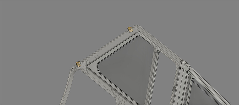
From here the next step was to finish the roof framing which this time around - as I'd found previously with the doors/windows - required some further corrections to various aspects of the original design blanks:
Back in January when I'd first done a test print of the roof framework just using a standard grey resin, I wasn't at all sanguine that it would be prossible to print such features on the grounds of fragility. Since then however, experience using eSun's hard Tough on the thinner parts of the rotor head has given me the confidence to print parts which previously would have been beyond tolerances. The roof framework now comes in two sections, the rear section mating with the front by the judicious use of brass mounting pins helping to fix alignment and strength of join:
Rear roof glazing and back windiow transparencies can then be installed from the outide:
- whilst the front roof glazing will push up into place from below due to the presence of the rubber beading around the lip:
Not atypically at such points, you find your interest wanting to take you on to one feature, only for such momentum to be checked by the realities of the construction process - in this case producing designs for the vacform bucks for the above features. Contemplating this it occurred to me that matters would be complicated by optional installation of the APX/BEZU sight which would require two versions of the transparency on the port side - one with a hole in the roof for the sight, the other with a raised panel of the same shape to give expression to the blanking plate present when the sight is not installed. Earlier than intended then I went back to study the manual drawing the for APX collar and just as well I did for I'd utterly forgoten the metal panel in the rear quadrant of each of the front roof windows into which the jettison handles are mounted:
It took a couple of days but in the end, collar and panels were in place:
The mint with the hole in it:
- and the alternative version with blanking plate installed:
Bucks for both versions are included in the print set:
It's arguable that you could just produce a single version of that feature and leave it to the builder to cut out the blanking panel (if they wanted to install the missile sight) but the risk of damaging the transparency during cutting and handling means having two versions will I think make matters more user-friendly.
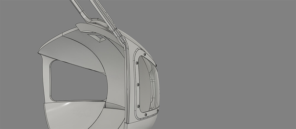
Turning attention to the nose and more nasty surprises appeared in close-up at the sheer amount of rivet and panel line detail needing expression; not only the raised panel of the footwell window:
- again a vacform part that will slot in from the exterior to meet a thin lip arouind the interior for alignment and gluing purposes:
- but also the nose access door and hinges:
- followed by the UHF antenna, demisting nozzles, and filler cap to port for the deicing fluid tank (capacity six pints):
I'm not sure what that strip of - guttering? - along the brow of the footwell windows on either side is, but it was a blinking rotter to produce. Fixing and aligning the windscreen section to the nose being a particularly critical function, there is a central mounting block provided beneath the windscreen, accompanied on either side by a locating notch to ensure the parts are symmetrically level:
I've a bunch more pictures of subsequent work but will keep that for the next update as I promised Mrs. B I'd modify the kitchen stove this afternoon:
Regards to all,
Tony
-
14
-
1
-
-
Health and Christmas duties have slowed Wasp matters of late but work IS continuing - a full update to follow in the New Year. Just to thank everyone for their kind comments & ongoing support with this project:
-
14
-
-
On 13/12/2023 at 12:01, Serkan Sen said:
In overall I am very satisfied with the result
So you should be Serkan: precise, immaculate work of the highest order.
-
2
-
1
-
-
Mike: I found it very hard maintaining an average temperature with my printers in a cold studio but didn't want any fuss about modifying or adding additional equipment to the unit so found the simplest solution is to have the printer in a small cupboard of some kind. For the Saturn 2 it's just an old office cupboard I found in a skip, up-ended:
The heat source is a 30W seedling mat propped against the side of the printer which left on for 90 mins before printing keeps the place at an average 23-25°C (you can always speed the preheat of the space up by blasting a hair dryer in for a minute or so). Opening a cupboard door is less hassle than removing/seating the original top enclosure on the printer tbh, whilst the opened lower door itself provides a handy fold-down worktop for cleaning the vat and plate &etc. afterwards.
Crude as this setup is I haven't had any temp. related print fails across multiple resin types.
I should add that resin is always pre-warmed by standing the bottle (top loosened to avoid expansion bursting it) in a bowl of just-boiled water for about 10 minutes, with build plate and vat left to warm up on the kitchen stove for the same amount of time:
It's all a bit Jack Hargreaves but works reliably.
-
2
-


Westland Wasp HAS 1: 'Ambuscade Flight: XT778'
in Work in Progress - Aircraft
Posted
1/6th of the way round the sun since the last update here and I'm shamelessly blaming interstellar debris as an excuse...
(This - interestingly enough - from an issue of Flight magazine published in the early 50s.)
Work on the Wasp has in fact been continuing in the background of the business of living in these times, so best to recount some of the key developments before what's happened and why get lost in the fog of the now.
Essentially I've been gradually working my way through the plethora of parts which amassed in CAD form over the past few months and which were long-overdue for translation into solid objects. Due to the combination of extreme thin-ness and compound curves on things like doors and so forth, this required a lot of troubleshooting with resin types and orientations in order to maximize part strength and avoid striated surfaces due to poor orientation of such curvatures in space. It also took a lot of customization of support types in VDT, which I have to say has proven itself a godsend for the variety of shapes involved here in terms of facility. Here are the final results of all these various print runs en masse:
And lest anyone gain a false impression that over time you ever get good enough for your efforts to succeed first time on more than a single part, this rarely rarely happens as the image below demonstrates in terms of the the level of failures required to iron out flaws and reach that point above:
The usual caveat applies to the following images in that they are shown freshly printed i.e., resin washed off but none of the print-support stumps sanded from surfaces.
The design of the rear wall of the cabin was revised in Fusion compared to the printed version shown here in previous updates, in that it now has the angled rear-window panels on either side of the central panel integrated into the one design:
It turned out to be feasible in the end to print these as one component and will, I think, prove a more accurate solution than trying to glue them on separately at the right angle during assembly:
All of that surface details remains present in the 1/32 version shown below as well, so my guesses about minimum feature size in the 1/24 version to survive scaling down seem to be holding up pretty consistently across the model so far:
Pretty much the same for the doors; both front:
- and rear:
- retaining equal levels of detail when scaled down to 1/32:
Door pillars too will look even nicer with the naviagtion lights installed later:
Too fragile to reproduce in 8k resin, the sliding windows for pilot/obervers had their frames printed using eSun Hard Tough resin:
Again the 1/32 version of these also survived the Alice in Wonderland treatment and printed as well. Amongst a number of other components requiring the black eSun resin for strength were the jury struts onto which the floation gear attaches as the front:
On the 1/24 version shown here you can see from the translucency down the sides just how thin the edges of that I-beam shape are. In this view below the translucency also betrays how thin the walls of the recess which the float gear struts fit into are as well - even after I added a small reinforcing panel inside of there on either side:
These features also reproduced at 1/32 quite pleasingly:
- however the walls of the strut recesses were just so molecularly thin at 1/32 that it necessitated them being largly filled in as a compromise between being present but not causing the print to fail in those regions (as it had done in tests):
Driveshafts from main to reduction gearboxes were also done up in black stuff as they'll be helping to support and align the entire engine/gearbox asssembly later on:
The rear cabin framing at 1/24:
- and at 1/32 both required the stronger resin to avoid breakage during kit assembly:
I wasn't sure if the door handles (on the right end) would work at 1/24 but they did:
More improbably however they also printed at 1/32 using the smallest feasible tree support I could devise in VDT:
Enormously pleased with how the nose parts came out in the 8k resin at both 1/32:
- and 1/24:
Some residual striation around the drain holes (necessary to avoid suction issues during printing) on both to tidy up at the same time the holes are filled. Detailing along the top surfaces was everything I hoped it would be, despite my heavy handling during support removal resulting in some breakages along the cheek window guttering (though these are easy enough repaired with some tape and the UV laser):
Underside and RADALT enclosures:
The weapons loadout had some attention in the form of prints for the Mk44&46 torpedoes:
Mk.44 first - this performed nicely at both scales:
I wasn't worried about support structures for that annular feature at the rear on the 1/24 scale:
But VDT came through again in allowing for some very fine structures to support it at 1/32 scale without causing undue damage to the torpedo casing in the process:
I just noticedthere's still a revision to do there at 1/32 as you can see the supports for the fins themselves weren't strong enough.
The propeller assemblies of the '44 at the smaller of the two scales:
Mk.46 behaved itself equally well at both scales, with no features failing:
Parifcularly pleased with part definion on the props for both sets, 1/24 looked nice:
- yet 1/32 turned out far less of a problem than I'd feared in terms of effective support processes:
The same story regarding all the fiddly detail on the carrier racks and sway braces which took so long to do up in CAD: in printed form there were no features missing or compromised at either sale (shown here at 1/24):
Suspension bands on the torpedo bodies also nice and crisply rendered:
Also added to the pile at this time were the landing light assemblies and transponders in both scale:
Fairing seen here in 1/24:
With no detail absent from the 1/32 version in relation to its larger cousin:
For reasons which as modellers I hope you'll understand, I couldn't resist doing a mockup of the Mk.46 torp at 1/32nd scale the other night, 'just to check' that the parts fitted together Ok:
Over the weekend I sat down and drew up a snag sheet for all the parts still needing to be designed in CAD:
The bulk of this as you can see involves the cabin & cockpit interiors, to whit I have the reference mosaics done up ready to start preliminary sketches for those areas:
Particular thanks need to go to @Ex-FAAWAFU, @Terry1954, @Anthony in NZ for imagery of the interiors which they've shared with me from their collections that will prove invaluable in the next phase, as well as all those positng stuff in the BM Walkaround for the Wasp.
Thanks for reading as always and hoping this finds all here in good form.
Tony