


Endeavor
-
Posts
254 -
Joined
-
Last visited
_5.56mm_Rifle_MOD_45162138.thumb.jpg.053e4f85b299efc3857bfa5c1911dc3c.jpg)
Endeavor's Achievements
")
Established Member (3/9)
531
Reputation
-
XXX
-
XXX
-
XXX
-
XXX
-
XXX
-
XXX
-
XXX
-
Thank you for the kind words. After I filled the slot between the cap and the body, and drilled the holes on the distributor cap, I painted the cap with thinned copper paint in lieu of primer. You are correct, the cap will be painted Tamiya Hull Red. So far, am successfully resisting the impulse to apply chrome Bare Metal Foil to the body of the distributor.
-
XXX
-
The canteen truck was built from a 1936 Ford V8 4 door saloon. It can be identifies by the grill, front fenders, front bumper, and the vents in the bonnet side panels. Ford did not make a truck with these components. The length of the doors indicate it's built from a 4 door saloon.
-
Prototype hubs...
-
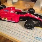
My model is intended to represent a museum quality prototype I am a bit reluctant to paint polished aluminum and stainless parts, so, for now, I sprayed the wheels with Tamiya clear. Tankerman’s painted Maserati wheels are a more accurate representation of the prototypes I think it will take considerable time before unpainted polished aluminum and stainless MFH parts will tarnish. You can polish the MFH white metal parts (for example, see the air intake to the carburetor on my 159M), but they will tarnish fairly quickly if not protected with a clear coat
-
The following is excerpted from my 159M build thread. Photos on the MFH website were useful… After placing the hub and rim on the MFH fixture… “To drill each hole in the hub at the angle at which its spoke enters the hub, I inserted a 0.4mm drill bit through each hole in the rim and drilled its corresponding hole in the hub.” “To assemble the wheel, I inserted each spoke through the rim, and then applied a drop of CA to the end of the spoke before inserting each into the hub.” “The final step was to slip each "nipple"- which are just 0.7mm X 4mm tubes - over the end of each spoke and through the rim to the correct position and then to apply CA.” Tamiya reverse action angled tweezers proved to be a very valuable tool. Hope this is helpful.
-
Adding some detail... I learned that I should have studied the plans more carefully as I neglected to drill a few holes. In addition, the building sequence outlined by MFH is much better than the plan I devised. Installing some of the small parts would have been much easier if I had not tried to be clever. Below you see the two lines I installed that run from the carburetor into the air intake. The lines are 1.0mm wire solder. Below are six pipes and a brass rod that connects the outboard starter to the crankshaft. I drilled two holes, filed off the lines left from the molds, and cleaned up the ends to ensure good CA joins. Two of the pipes are connected with heat shrink tubes and PE clamps. Below you see one shrink tube and clamp installed and a look at the PE parts. Notice that three of the PE parts have had the remnants of the sprue connections filed off and two "ears" folded up. The PE parts are 0.8mm wide. Below are the two pipes with heat shrink and clamps installed. The heat shrink tubing was applied with the gentle prodding of a soldering iron. The clamps were attached using two pairs of pliers. The steering arm was installed. There is a pocket in the firewall to provide clearance. These two photographs show the empty space between the engine and the radiator that will soon be occupied by four of the parts shown above.
