


Engineer66
-
Posts
261 -
Joined
-
Last visited
Recent Profile Visitors
1,362 profile views


Engineer66's Achievements
")
Established Member (3/9)
337
Reputation
-
Thanks Mr? Matthews 😀 Cheers Pete, Surprisingly enough the amount of resin used is tiny, I'm still on my first bottle of this stuff, it seems to go a long way... Cheers M3talpig I've wanted one for a long time but they were way out of my price range, it was only when I discovered how much they had come down in price that I began seriously considering getting one. I bought a filament one initially and that is great for bigger jobs, but no good for stuff like this, which i regretted after the first couple of weeks. It still gets used quite a bit though so it's not a white elephant! About six months later I got a bonus at work and decided to invest in the resin one. To be honest it's one of my best purchases to date, (after the LED lighting i installed under the modelling desk!). Go on, do it, you won't regret it... As promised last night here's a better picture of the seat runners. If it helps illustrate what the printer is capable of each runner is 12mm long and the upright tube sections the seats sit on are 0.8mm dia. If you look carefully you can just make out the bolt heads in the mounting plates! One other item I forgot to mention last night... Private Milligan now has a way to wind the window down if it gets a bit warm... (I don't think I need to point out which one is the unmolested kit part). That's the lot for tonight folks, Just a brief little bonus episode! Take care and see you all soon. Alan.
-
Evening All, My apologies for the lack of updates and my tardiness in responding to your comments. There really is no excuse, however I am going to blame it on work, family and other commitments! Before tonight's meager update I shall deal with the incoming post... Thanks Steve, You're right I am as chuffed as a dog with two wotsits! It's a bit like the theater, the public sees the final performance but not the multitude or rehearsals that went before. For each part you see here there were several failed versions that now reside in a pot at the back of the bench. The Software is pretty straightforward once you get the hang of it, it's all down to breaking an object down into its component shapes. Thanks John, It's one way of practicing with the software and getting used to the printer and the resin. If i change resin the calibration process starts all over again! If anyone is thinking of building a post war scrapyard let me know I have loads of damaged body panels available 😀 Thanks Mancunian, You don't have to produce a set of drawings for the parts, you build it up from basic shapes, a bit like making something out of Lego. Each basic shape can either be a 'solid shape' or a 'hole shape' If I was going to make a mug for example I'd start with a 'solid cylinder' then to hollow it out put another slightly smaller 'hole cylinder' inside it. For the handle you take a ring and cut it in half and then stick that on the outside. You essentially then click a button that says 'export' and the software converts it into a set of instructions the printer understands. It's actually quite easy to pick up, as I say if you can build a basic car out of Lego then you're halfway there. (I must add that I'm still only using Tinkercad and not fusion at this point, that is a whole different kettle of fish! 😱. Not being modest here, just honest 😀 By 'foot pedals' if you mean the square shapes they are supposed to be packets of ciggies! the pedals in the Tilly are circular, as you can see below. OK, correspondence corresponded with now on to the measly amount of progress... As I say I have had other things taking my attention away from the Tilly for the last couple of weeks, (checks date of last update and then looks at Gil Elvgren 😁 calendar) By Eck, its actually been a month, better pull my finger out! After the work so far I decided to try and do something about the interior floor. The load bed didn't need anything other than needing an access hatch above the diff scribing in which i did earlier. It was the passenger compartment that threw up the challenge. the original vehicle has strengthening beads pressed into the floor pan to give it rigidity and stop it from drumming. My dilemma was how to replicate this without it looking like the cat had been chewing on it... This is the sort of thing we are after, I'm not tying to make it 100% accurate as you probably won't see it in the end anyway! Picture borrowed for illustrative purposes only (not mine and I will remove it if requested). Option number one was to try and scribe and sand in the beads as grooves, but a couple of tests on a scrap piece of plastic proved the cat could have done a better job. Option number two involved 3D printing a new floor, now while this could have come out a treat with a favourable wind and if the gods had been on my side and the planets were in alignment and I'd been wearing my lucky socks etc. I decided to rule this out as: A. I wanted to try and keep as much of the original kit as possible (I'm only fixing the bonnet sides remember!) and B. the amount of time it would take would be immeasurable, (do you know how long it took to create a padlock, never mind a full car floor!). Option number three was to laminate a piece of plastic card with holes in over the existing floor to give the impression of the pressed in beads. I ruled this option out as the thinnest plastic I could find was too thick, and I cannot cut out accurate lozenge (is that what they're called?) shapes if my life depended on it. That left option four, the only problem was I didn't have an option number four! So it sat like this for a couple of weeks whilst I gave it a good coat of thinking about. Then one day whilst rooting around in one of my many (and I mean many, SWMBO will confirm this!) modeling supplies drawers for a length of brass rod to fix something else I came across a 3 inch square piece of self adhesive chrome foil. "O look" i thought "a 3 inch square piece of self adhesive chrome foil" and moved it aside to locate the rod I so badly needed. I only remembered the foil the following week when I was plugging in a new web cam and had to move my Silhouette 2D cutter out of the way, the one I use to make masks and such like. At this point I had a rare moment of inspiration and realised that there was an option number four after all... Any way, after having a sit down to recover, I took a photo of the floor pan, uploaded it to the computer and then opened it in the Silhouette software scaling it to size. On top of this I drew the outline of the floor and the various strengthening pressings for the passenger side. This was then copied and mirrored for the drivers side and a couple of changes made for the pedal cut outs. The chrome foil was carefully loaded into the cutter and I clicked 'Send To Cutter' and disappeared off downstairs to make a cuppa. On my return the cutter was silent and on the floor in front (it was on the edge of the desk and I forgot it ejected the sheet after it was done) was a set of nicely cut floor pan laminates. This is what I ended up with after they were parted from the backing and burnished into place on the Tilly... And from a slightly different angle. Quite passable and give the look I was hoping for, even if they are a bit on the big side. The eagle eyed among you will also have noticed that I've installed the pedals as well; another session with the Mars. These will be replaced as since I did this I've printed a better set with more defined rubber grips on them. After looking at the picture of the 1:1 scale floor above I decided that the Tamiya seat mountings (four upright posts with a horizontal one between them on the floor) would not fit the bill either and would have to go, Time to top up the resin in the printer... The picture below shows (not very clearly I admit): Top left the Tamiya versions after removal from the kit floor. Top right my first attempt using copper wire and contrail tube Bottom left my first attempt at 3D printed ones Bottom right the final versions straight off the printer before support removal or curing (I know this bit is not the best picture, the camera keeps focusing on the green seat and not the grey resin. I'll try and take another pic that shows the detail a bit better). That's as far as I've got so far, hopefully I'll have another update soon. Thanks for looking in and the comments, it does motivate me to do more. Cheers Alan.
-
Hi All, Sorry for the lack of updates, it's been a bit manic at work meaning too many late finishes. Any time I have had has been spent knee deep in CAD software and/or up to my armpits (well fingers really) in resin. Having spent several hours measuring, drawing and printing (and drawing and printing and drawing and printing...) I managed to create some bonnet sides and a radiator grill (well that's what they look like to me anyway). However due to me trying to be way too ambitious and get the vents thin it would appear that the scourge of the restorer has already bitten and some of them look like they already have Tin Worm... Not to worry, lets go back and do some more drawing and printing and drawing and printing, (you get the idea, nobody said it was going to be easy...) After thickening up the edges slightly I finally managed a set of parts that would fit... I know the radiator grill is damaged bottom left but I have a couple of spares ( more than a couple actually) With a little bit of trimming and sanding we now have a grill and bonnet sides 😀 The fit is actually quite good, here they are just dropped in position so look like they don't fit; they do, trust me I know what one that doesn't fit looks like, I have fifty of them! Whilst I was waiting for the bonnet sides to print I got into my 'What if?' mode and decided to create a few more goodies at the same time... I'll let you work out what they are... Finally for tonight, remember when I sanded off all the fittings on the back of the body? Well this is what it looks like now that I've put them all back on again... That's it for tonight folks, Tune in next week for another thrilling mildly interesting episode.. Alan
-
Take the plunge if you can afford it, you won't regret it. I was fortunate in that I was given a load of African River Vouchers...
-
Evening All, Today has been a day of discovery and experimentation and destruction... I spent the morning with several mugs of Yorkshires finest and the tablet watching videos and reading blogs and faceybookey groups on 3D printing and spent time calibrating the printer; Which turned out to be easier than it sounds really: 1. Download the file for a a calibration tile thing 2. Print it (takes a while) 3. check the resolution 4. change the exposure settings (the printer uses a UV light source to cure the resin in the vat, lifts the build plate a midges whatsit and then cures the next layer) 5. repeat from step 1, After a couple of hours of this I seem to have it got it 'Dialled in' to use the technical term, so whilst it was printing each tile I needed to find something to do, cue the destruction... From this: To this, in four easy saw cuts (and a bit of abrasive action) Whilst cutting off the bonnet sides I also decided it would be a really great idea to give myself even more work and went ahead and built up the rear truck bed, carving off the frame fittings and tarp' hooks etc. in the process. Now comes the easy bit... Replacing all the bits I've cut off! Stay tuned folks, I'll be back with more updates eventually and several probably unrecognizable lumps of resin... Al
-
Thanks Rob, I've been after one of these for quite a while and couldn't justify it. I received a bit of a bonus from work and offered to 'share it' with the rest of the family, my plan was accepted, all I had to do was plan a weekend away... 😀 Hi APA, to be honest I'm not overly impressed with the wheels, the tread looks more business like that the Tamiya wheels which look a bit 'civillian' to me (gets plus points). However there are quite a few pin holes in the rims (gets minus points), so the Jury's still out on this one at the moment. I think you could be right there, a tin of black paint would have been cheaper! I keep telling myself that in the long run it will save me a fortune in aftermarket... I know what you mean Colin, it is very much 'plug and play', however its the bit before you plug in the flash drive that takes some thought and practice... I've found Tinkercad quite easy to use, its very much like sticking shapes together to build things, a bit like Lego. Spent some time on the interweb today and running test prints to try and calibrate the exposure settings and 'Z-Lift' Makes it look like I know what I'm talking about (I don't really I'm just good at pretending!) 😉... Thanks Das, I'll check them out, now thinking about printing the wheels now! What have I let myself in for? 😱 Hi John, I must admit I'm not over impressed with the SKP wheels, there's quite a few pin holes in the rims. A Bottle of matt black would have been easier and cheaper 😀 I shall have a mosey on over and check out your build...
-
Hi all, Its time for me to stop lurking and come out from behind the curtains and create a WIP thread. I started a thread for an AA Stolly a few years ago but it sort of stalled. You never know I may pick it up again one day. Anyway, having been inspired by the quality of work I am seeing on here I've decided to take the plunge and start another thread. This time I've decided on something a bit simpler and more straightforward with no conversions, aftermarket, extra details etc. (Hmm, we'll come back to this in a bit...) I am going to attempt to build (and complete!) the Tamiya 1/35 Austin Tilly 'Out of the box' which I received as a Christmas present last year. This one 'ere... First thing I did was to see what aftermarket was available, yeah, I know, that plan didn't last long! (it's the natural course of action isn't it, everyone does it, it's perfectly normal? please tell me I'm not the only one...) and decided to invest in a set of these... You know I said we'll come back to this being a 'simple and straightforward build'.... Well... I took a deep breath, put away the plasticard and strip at the back of the darkest cupboard I could find and carefully took the lid off the box and started to examine the contents... Things were going well until I had a look at the bonnet sides and thought to myself (Which as I'm sure you will know is a very, very dangerous thing to do) "Oh I don't like the look of those, you can't see through the bonnet louveres loovers luoveers them vent things... Several experiments followed involving the use of tin foil, lead foil, thick plastic, thin plastic, crash molding and flames (always the fun bit) alas each time the results were decidedly sub par and not worthy of display. It was while I was waiting for the burns to heal (I'd tried crash molding remember,) that things began to get out of hand, and I mean really out of hand after looking on other forums and getting drawn into TheBarons outstanding Sea Vixen build I slowly came to the conclusion that to get them there venty things you can see through I am going to need a bottle of this... and one of these to put it in... Oh and not forgetting a quick download of Fusion 360 (how on earth does TheBaron do what he does? It took me three weeks just to be able to draw a square, never mind create an accurate fuselage and a RR Avon to go inside it!) and some experimenting with Tinkercad. I can see interesting things on the horizon... Wish me luck all, "I'm going in (headfirst with no safety net)"
-
Hi, really interesting build. this clip has some really good close up footage of the crew loading the charges and rockets. https://youtu.be/2I51-H2hqc8 Al
-
Thanks again chaps for the replies. Ozzy, I've seen the transfer and PE zimmerit but decided to 'do it properly' using 'no-nails' and a Tamiya tool to scribe the pattern...never again! It goes everywhere! Jack, thanks for the link, really useful, I'm now starting to narrow down the time period. thinking of leaving the Zimmerit missing from below where the track guards where. My logic is it was applied in the field and the crew couldn't be bothered to remove the guards, since then it has suffered damage and some guards are missing. Hence some missing guards and only zimmerit above where they would have been. cheers Al
-
Thanks for the replies chaps. when looking at the tank the gap between the road wheels and fenders is relatively small so the odds of getting a mine in there would be small so I was assuming that field applied zimmerit would not have been applied below the track guards as it would have been a pain to remove and re-fit them. Then I saw the photos posted by Jack and they show the coating going all the way to the bottom behind where the track guards would have been. I've seen quite a few pics showing this and wondered if it was factory applied and would the tanks have had the track guards fitted as there are quite a few pictures showing tanks with no track guards. Where they always fitted? cheers Al
-
Hi all, i apologise if this has been asked before but I can't find anything after searching. I'm building the Tamiya mid production Tiger 1 and have decided to attempt to apply zimmerit. I am also planning on removing some of the side 'mudguards/fenders' as damaged. My question is would the zimmerit have gone all the way down the side to the bottom of the hull side, or would it have been applied behind the side mudguards, (the ones that stick out the side) so if I remove some of the mudguards would the area underneath be covered in zimmerit or not? thanks Al
-
Trumpeter 1/35 British Heli - Its a Chinook
Engineer66 replied to simmerit's topic in Work in Progress - Aircraft
How about a set of Nebelwerfers in various scales? Cracking job on the sand filters, they really do look the part. It's a bit strange but I'm that used to seeing pictures of Chinooks with them fitted they now look wrong without them. Keep up the persistence. Al -
Ah Ced, you're making me feel all nostalgic now! When I was at 6th form we used to write our program on a 'form' which was then sent off to the local university for punching and then loading into their UNIVAC (iirc). If you hadn't made a mistake you got a print out on that lovely stripey tractor feed paper and a small stack of cards about a week later. And yes I have used one of those punch machines to produce new cards for amended code. :-) I foolishly left 6th form after a few months to start working for a high street bank as they promised to give me money every month and didn't set homework! After a very short spell as office junior ( a proven inability to make a decent cuppa can be a real career boost) I was entrusted with changing programs on the branch terminals. We had five gaint Burroughs machines, each the size of a sideboard, with no fancy 'display screens' just a tractor feed printer with a daisy wheel that would have your fingers off if you strayed too close and a keyboard that as you pressed each key you could feel the clockwork! Changing programs involved feeding a length of punched paper tape into the beast and took about 30-40 minutes. The dangerous bit was rolling it back up again afterwards. I remember there was a handle clamped to the edge of a desk where you fed the end of the tape into a slot and then us the handle to wind it back up, and you had best keep your feet out of the way, cos if you stood on the tape without realising and tore it you were in serious do-dah! You would have to report to the branch manager and request permission to get a new tape from the safe. And this was in the days when even the assistant manager called him Sir or Mr Xxxxxxx. But hey I was working with real computers and was King of the neighbourhood 😀 Sorry for for the thread drift Perdu but I blame it on Ced and all this talk of times past making me all nostalgic. It wasn't as much fun when they updated to new machines and I had to use my 8 inch floppy instead... Al
-
Not been on here for a while due to some unfortunate family matters I've had to deal with. My condolences on your loss Crisp. Lovely work on the jump seat and steps, it's a shame to hide them. Glad you took the bait I laid and sent for the wing nuts Al
- 2,565 replies
-
- 3
-

-
- Flightpath
- Hasegawa
- (and 1 more)
-
Tamiya T-62 in 1/35 or is it 1/32?
Engineer66 replied to Engineer66's topic in Work in Progress - Armour
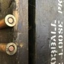
Sorry I didn't reply earlier but I've had a lot going on at home and have not been able to log on recently. it's sold as 'beading wire' you can find it in the jewelry making section, I have two types, they still sell the packets but not the reels, which are the ones i prefer. I also have a small stock of electricians solder which works well. This is the stuff I use: Thanks for the comments all. Alan

