

caterhamnut
-
Posts
523 -
Joined
-
Last visited
-
Days Won
1
Content Type
Events
Profiles
Forums
Media Demo
Everything posted by caterhamnut
-

A BIG Rolls-Royce Version II 1-7-2020
caterhamnut replied to Codger's topic in Work In Progress - Vehicles
Just wow. For some reason I’d not found these build pics, despite knowing Chas had built the Rolls.....simple stunning. Two Masters at work....saved for ref! I love the chassis and engine work - the finish and detail is staggering. Going to take some time and go back over this properly when I get a chance! -
Beautiful build of a pure classic - I am terrified of such paint finish on such a big car - guess that is why my cars have all been 'F1' or narrow-body so far!!! lol
-
Caterham Superlight - Tamiya 1/12 Custom Build
caterhamnut replied to caterhamnut's topic in Work In Progress - Vehicles
It may not be visible in the photos, but the back of the printed switches have a square pin, which locate in the dashboard holes - so all about the correct location/spacing etc. The holes on the dash are a lot smaller than the switches or dials - which also have a small locating step on the rear. No such thing as a dumb question! -
Caterham Superlight - Tamiya 1/12 Custom Build
caterhamnut replied to caterhamnut's topic in Work In Progress - Vehicles
This car has an FIA roll bar fitted - the kit comes with an old style roll bar you often see on Japanese cars for some reason - and of course the R500's had full cages. I printed this using a slightly different support method for the printed parts - usually you place many small supports, but these can lead to a lot of marks that need to be removed, or worse, 'sagging' of the resin around the parts. So for these thin 'rods' I instead drew a thing 'fin' in the solidworks model - this would provide support all along the length of the bar, and be easy to sand off once printed - it worked well. Test fitting... So that is where I am as of now...the photos below show most of the parts so far started 'assembled' loosely - nothing is fixed into position here, so it all looks a bit wonky! Next stage is probably to aim to fix the engine into place, once I am sure everything else has been done that will be much harder to access once the engine is in. -
Caterham Superlight - Tamiya 1/12 Custom Build
caterhamnut replied to caterhamnut's topic in Work In Progress - Vehicles
Dash - although the dash in the kit is the same layout as this model, the Superlight has a carbon dash - the texture on the dash would have to be removed to cover the dash in a carbon decal - but this would be very difficult to do around all the instruments and switches - so of course it requires drawing up and printing.... I covered the dash in the carbon decal, and then set about the switches and dials, which I elected to make all separately. I coloured and cut tiny pieces of foil to represent the lights within the rocker switches. I drew up the instrument gauges... Still work to do on this - and these parts are just placed, not fixed yet... -
Caterham Superlight - Tamiya 1/12 Custom Build
caterhamnut replied to caterhamnut's topic in Work In Progress - Vehicles
Other bits and bobs: Steering wheel has a central pad, unlike the one on the R500's ....and the interior tunnel top requires sculpting. Handbrake has to be added (not in the kit) I had to make some rubber interior mats... Thanks mate -
Caterham Superlight - Tamiya 1/12 Custom Build
caterhamnut replied to caterhamnut's topic in Work In Progress - Vehicles
After quite a bit of effort.... ...and figuring out how to support the model... The manifold will attach to the block with bolts, as everything lines up - thanks to the solidworks model! But I have not modeled the chassis or panels, so getting all those hard points to line up is a challenge! It did take a few attempts... Once I selected the parts, I added some detail - in this case the lamda sensor... Once I had the fit ok, I painted the exhaust. The main exhaust can will be covered by a heat shield. In these photos nothing is fixed into place yet....just test fitting. -
Caterham Superlight - Tamiya 1/12 Custom Build
caterhamnut replied to caterhamnut's topic in Work In Progress - Vehicles
Model engine update before exhaust and fitting: -
Caterham Superlight - Tamiya 1/12 Custom Build
caterhamnut replied to caterhamnut's topic in Work In Progress - Vehicles
For anyone interested, here is a video of us taking our real car apart (properly apart!!) before a rebuild - this is from about 12 years ago now - but you can see how good the model is in terms of chassis etc etc... -
Caterham Superlight - Tamiya 1/12 Custom Build
caterhamnut replied to caterhamnut's topic in Work In Progress - Vehicles
Right - where were we..... It's been a while, but only in terms of an update - work has been progressing, inbetween a few foreign trips...FB has seen some picture dumps, but not here.... So although a lot has been done, there is still tons to do, with almost every aspect of the car having to be either drawn up in CAD and printed, or scratch built. Very easy to under estimate how much work will be involved - and time....jeez! So I had completed the 'core' of the engine - that is, most of the components were assembled OUT of the car. Things like exhausts have to be fixed to the block AFTER the engine is in the chassis - just like the real thing of course. So I have to determine what needs to be done to the engine AND the engine bay before the engine can be located. I also have to design and model the engine mounts. But without doubt the biggest pain is the exhaust manifolds - despite lots of photos, there is no easy way to get each manifold the correct shape in CAD, other than visually and trial and error - so after learning how to actually draw these up (3D sketches in Solidworks) I started printing off samples. I actually got it pretty close first go, so it all comes together quite well - of course I cannot use the exhaust can from the R500 models - so a new one is drawn up! (I modeled the manifolds on the R500 models with thick solder wire - long before the CAD/3D printing process, so could not use any parts from those...) Before I could work on the exhaust, I had to fit the gearbox (in order to locate the engine in the engine bay correctly) This Superlight has the Caterham 6-speed box fitted, so I made the top plate that will be SLIGHTLY visible from within the engine bay. This now gave me the correct fore/aft fitting of the engine, so I could work on the engine mounts. True to the real ones, these are a very tight fit around the components, such as the exhaust and particularly the alternator. They locate into corresponding mounting points in the chassis rails. So at this point I have the engine location fixed. Now I have to figure out what has to be designed, made and fixed in place BEFORE the engine can be actually located permanently. The exhaust is a 'floating' fit - by that I mean I have to partially insert the engine, then thread the manifolds through the gaps, and bring everything into place as the engine is lowered - just like in 1:1 scale - a right pain in the arrrse. But before that I have some other things to fix in place. Any wiring that may be hard to get too later. A carbon filter on this car (usually removed) sits in the engine bay on the side skin - I drew this up in CAD and printed it - I'll add piping before fitting... You can see the black canister next to the dash in this pic. Quite a big job has been the footwells. The Tamiya kit is based on an older Caterham, which had a short passenger footwell (where your legs stretch out under the dash) - later models have an 'extended' version, which gives more room and usually holds some electrical boxes - in the case the battery - on top. It brings the footwell out to the same place as the pedal box on the drivers side. I had to make this, as the kit has a short version. I tried different methods - plasti-card, folder ali-sheet and in the end a 3D printed version - it was just easier to draw up the awkward shape in CAD than try origami with ali sheet. A few attempts here: The box with the hole in it is the ali kit version, and the hole is for the steering column. I sprayed both boxes to match the rest of the aluminium interior panels. I haven't got a picture of these in situ yet because it requires 5 hands to hold them in place with the bulkhead above, chassis rails etc etc - it is going to be a one-hit fitting process with the engine and engine bay chassis rails! Oh hang on - I have... On to the exhaust.... -
Caterham Superlight - Tamiya 1/12 Custom Build
caterhamnut replied to caterhamnut's topic in Work In Progress - Vehicles
Back to the chassis: I fitted the suspension, front and rear. Nothing much to change on the kit at this point - it is pretty spot on - I tweak the wheel track slightly with the hubs at a later point. The layout and geometry is spot on, and you can actually change the 'set-up' and see the changes if you fiddle with the trailing arms and de-dion tube - I need to video it sometime in the future! I also painted and fitted the diff and the fuel tank.... I added some heat shrink rubber tube on the end of the steering arms to represent the ball joints at the end -
Caterham Superlight - Tamiya 1/12 Custom Build
caterhamnut replied to caterhamnut's topic in Work In Progress - Vehicles
Thanks very much S-B. I'm self-teaching Solidworks, having only dabbled through work - and if you look at what I have done so far, it is all 'push/pull' from solids, then extensive use of fillets - so very much at the simple end of the software😉 -
Caterham Superlight - Tamiya 1/12 Custom Build
caterhamnut replied to caterhamnut's topic in Work In Progress - Vehicles
cheers - Anycubic Photon -
Caterham Superlight - Tamiya 1/12 Custom Build
caterhamnut replied to caterhamnut's topic in Work In Progress - Vehicles
Dipstick! Brass and ali tubing for the dipstick tube, and I printed the 'handle' - another tiny part! of course it 'works'.... So that was the main block sorted - the starter motor goes on after the bell housing... You can see I have also started to add some wiring to the block. But the next big bit to model was the air intake manifold. This was going to be a challenge in CAD for me, but managed it - best way to learn a program is a 'real' project! So the end result works, but it is by no means a 'good' CAD model! The splits involved made drawing and printing it more easily. The throttle is made separately and bolted together after painting, as will be the foam air filter. I don't have this part on my car anymore, so had to rely on photos - although I was able to go and measure some bits halfway through the process - ebay and autofactors are good resources for parts pictures by the way... Test print of the whole air intake assembly, to check fit and scale etc Lots of test prints to find the best orientation etc At this point I glued all the bits together and primed one version, just to get a clear overall view, and again, to test fit! I'll have to move the engine mounts in the chassis! Painted the air intake black, and added some variation in terms of blacks for the injectors and fuel rail etc. None of this will ever be seen again once fitted to the engine! Bolting the throttle on... Rivet! Holding the throttle pot on...(visually anyway) Gradually getting a kit of parts... More wiring... The braided hose is actually black elastic cord... I printed some of the rubber hoses as solids for assembly, as the ones between the head and the air intake manifold actually help to hold them together, and bending rubber tube would have added too much strain...same with the ends of the HT leads - I actually printed them already on the distributor cap. So that's where we are at this point! I printed some different scales for 'future projects' - Blue is 1/8th scale, painted is the 1/12 scale, grey is 1/18th for the Kyosho diecast Caterhams, and the tiny one is 1/43rd! That is 10mm across and I printed it whole to test - it would be assembled separately in the same way as the 1/12th - incredible detail being picked out by the printer though... Before the R500's went, I managed to grab a few quick photos... -
Caterham Superlight - Tamiya 1/12 Custom Build
caterhamnut replied to caterhamnut's topic in Work In Progress - Vehicles
Hi Jeroen - nope, just different colours, from the same company. There are different types though - hardness etc, clear, flexi..... Every type is different in terms of curing time and sometimes the way they handle detail - including colours! -
Caterham Superlight - Tamiya 1/12 Custom Build
caterhamnut replied to caterhamnut's topic in Work In Progress - Vehicles
lol - thank you sir! As someone mentioned in my R500 build diary - it is interesting how the model-making 'scene' has developed over those 17 years (when obviously I stopped for quite a while!) - with the internet changing hugely, availability of parts, knowledge, youtube guides - I have learnt so much from forums like this one - and now resin 3D printing at the hobby level....exciting times! -
Caterham Superlight - Tamiya 1/12 Custom Build
caterhamnut replied to caterhamnut's topic in Work In Progress - Vehicles
Engine - so this is the big part! Having scratch built the 2 engines on the R500's out of wood, plastic etc, machined slots in the cam cover etc etc, I wanted to 3D print these. But that meant drawing a k-series up in CAD. I'm self-teaching, so it was a bit daunting - but once you know where the buttons are, an engine block is not actually so complicated... I took measurements from many photos I have of our engine over the years, and measured the engine outside in the car - which due to access is actually pretty difficult - I could measure the cam cover easily, but that was about it - but long story short, I was able to scale the photos once I had a base measurement. Once I had pretty much finished with the CAD and engine build, I had access to a real engine that was not in the car, and measuring this I found I had been pretty damn close. I drew the engine 1:1 (I can scale when I print) and I have split it into the actual parts - so the block consists of 5-6 'layers' (although I printed the middle bits in one lump) I found out that the easiest way to model and build the engine is to do it exactly the same as the real one - so the alternator is attached with a bracket in the same way as 1:1, coil is bolted on the same way, throttle uses 4 bolts etc etc. I had a few parts lying around - like the sump - which I was able to measure properly and then scale others from that. Richards car has the plastic Rover air intake, which was going to be a challenge to draw for me in CAD. I started roughing out the overall shape - main measurements were the height of each layer in the block. Once I got those correct, I added most of the detail in by eye. I printed a VERY rough block to see if the size/scale was going to work, then a slightly more refined version at different stages. I'm learning about the 3D printing as well, and you learn to design the parts to make the printing process - particularly the orientation on the build plate - easier. The large holes are for the resin to drain - I hollowed out the 'real' one later. example of the 3d printer plate layout/slicing - where you add supports etc - I'm learning! Some examples of parts being printed - there were lots of versions, so these photos cover about a months work from now on! I'd do the occasional print with everything 'turned on' in the assembly, just to see the size etc - in the end, every component, like coil, sump, bellhousing etc was made separately. But it was getting there... Here are some screenshots of the complete engine in CAD... I printed a 1/8th scale block - 'just to see' - ummm - 1/8th scale model.... Eventually I got to the point where I was happy with the block - you can see the progression here: Next I made the ancillaries that bolt to the block - alternator, coil, air intake, throttle, cam belt cover, pulley, starter motor etc etc etc I drew up the alternator in three parts - the casting, the black plastic cap at the end and the center coil. This would make the painting easier, and allow open vents etc. I could have made the pulley separate I guess... I added the new parts to a test block to test the fit... Drilling the alternator bracket... There comes a point where you think 'what am I doing modelling this...?!' - in this case, it was when i was drawing up the crank sensor... By far the smallest part I have printed.. (get used to that pen) Adding paint really transforms everything! That crank sensor needed a flywheel - which needed a clutch (which would be hidden by the bellhousing, visible in only a few gaps - but what the hell - in for a penny, in for a pound!! Forgot the gloves... Testing silvers for the block... I used an oil wash to make it look grubby with.....oil! ..and started to paint and add the other parts - here is the coil being bolted in place... Having tried the 1/8th scale, I thought I'd try a 1/43rd one-piece engine, just to see! Tip time! Metallic paint pens (crafts etc - Amazon) - brilliant for different metallic finishes and easier to apply to details! About £10 for loads... Dip stick next.... -
Caterham Superlight - Tamiya 1/12 Custom Build
caterhamnut replied to caterhamnut's topic in Work In Progress - Vehicles
Cheers Codger - too kind😉 -
Caterham Superlight - Tamiya 1/12 Custom Build
caterhamnut replied to caterhamnut's topic in Work In Progress - Vehicles
As on previous models, the detail in the engine bay is a highlight of these models - I made a start on the ECU/battery area. Richards car has a newer heater than the kit, so I referred to photos and drew it up in Solidworks, before printing it off... ....I'll plumb that in later. Next, the ECU and associated electrical relay boxes etc - again, drawn up in CAD and printed... I tweaked the plugs to give me holes, as I intended to 'wire' the boxes for ultimate detail! Once printed I drilled out the holes slightly to help my assembly - you can see 2 broken off drill bits in this photo!! I took an electrical wire apart to get some really thin copper wire, and then painted this in lots of primary colours, so I could add the wiring... This was fiddly - but worth it for the result, IMO! I then took the thinnest heat shrink tube I could find and stuffed the wire into it, before shrinking the tube VERY carefully, and bending the whole lot to suit... ...and the ECU box (now painted) - a LOT of wires! ...small piece of heat shrink, and a piece of elastic thread to look like the wiring loom. Used some ali tube for the ecu supports. -
Caterham Superlight - Tamiya 1/12 Custom Build
caterhamnut replied to caterhamnut's topic in Work In Progress - Vehicles
At this point I decided to copy many people who make little pieces of workshop to compliment their photos - and made some chassis trolleys based on the ones we used for our real chassis! Simple plastic tube and I drew up and 3D printed some castors. Result! Engine crane and support next... ...more of that later. -
Caterham Superlight - Tamiya 1/12 Custom Build
caterhamnut replied to caterhamnut's topic in Work In Progress - Vehicles
Cheers Codger - the 'whole car' might be an option - I'm getting close to have drawn up most of it! My only thought then is at what point you run in to licensing issues!! ......sshhhhhhh -
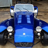
After finally waving goodbye to my 2xR500 models that I have been carrying around the world for 17 years, I'm on to my next Caterham model - also 'ordered' back in 2002. I have very patient friends! But I'm on a role now, so hopefully this one should only be about 9 years.... This will be a model of a K-series Superlight - so no cage or decals (thanks god) but the same level of detail - in fact probably more after 17 years 'experience'... Here are a few shots of the 'real' car: But in this model I have already made extensive use of my new 3D printer. I have pushed myself with Solidworks, and drawn up the k-series engine entirely - every part drawn up and printed. Have also made a start on ancillaries like ECU etc. This first load of pictures will be a big dump, as I started a month ago but did not do the sensible thing and start the build diary as I went - so this is the catch up... This version of the kit is getting harder to find - it has not been re-issued by Tamiya. I got this one in 2002! I actually end up using less and less of these kits with these builds - but nothing replicates the chassis or ali bodywork, which is superb. Because the engine is different from the BDR in the kit, I have to block off the hole in the bonnet that is for the old-style carbs. Also have to fill the spare wheel carrier bolt hole on this particular car. I fitted the interior/floor ali panels - I'm not 'weathering' the car as such, but added some wear and tear to reduce the shiny ali look. The Tamiya kit comes with an old style heater (about 3 models back I think!) and this model has a newer version - I had to make a new bulkhead surface to cover the larger holes on the kit version. I had started the engine at this point, but once the owner sent me his touch-up paint pot, I primed and sprayed the other aluminium panels, rear wings and nose. The paint is a Ferrari metallic grey, so also needed a clear coat. On this kit, the wings and nose are 'carbon fibre' and these parts come with a 'carbon effect' pattern. It is a little crude, but I am going to keep it for the nose strip and the front wings - I shall 'dull it down' a bit with some Tamiya Smoke paint.
-
Young - ha!😉
-
Fantastic - you do yourself a massive disservice mate. It looks superb, and whilst I am sure the effort involved for you was huge, the testament is that it looks so good that none of us would have realized there was any issues at all, simple as that. Whilst it is a 'simple' kit in that it goes together very well, it is probably the hardest to attempt with any 'condition' simply because of those damn screws! lol - they are tiny (AND there are 5-6 different sizes that are JUST different, so I had to check every time I used ONE! The bonnet catches had me almost throwing the damn thing across the room - trying to thread the catch onto the end of the spring was genuinely the single most frustrating part of the whole build 🤣 - and then I found that my paint was so thick that I had manged to 'close up' the little tab on the bonnet so much it wouldn't work anyway....🤬 You've nailed the classic look perfectly, and I do 😍 those wheels - love the red and gold. As has already been mentioned, those first two finished pictures look like a real car...(actually so does the 'build' pic with the front wheels fixed.... So be very justifiably proud of the result - only you can understand the effort needed, but we can all appreciate it. I hope you keep going with more - if you can handle those god-damn tiny screws then I don't see what can hold you back!! You built it at a proper rate as well...mine took 17 years. But remember, it is seeing projects like your Rolls (which I remember from when I first joined this forum - annoyingly photobucket screwed the pictures?) that inspired me to progress with modelling, and showed what could be possible. Cobra next? 😉
-
Mercedes W196 Scratch Build
caterhamnut replied to albergman's topic in Ready For Inspection - Vehicles
I'll add it to the project list!!😁 Many years ago I carved a 'J-Class' Yacht half-hull, using the ships lines plan....that might work! I wonder if one can pick up a set of Silver Arrows bodywork plans....lol


