

larchiefeng
-
Posts
1,448 -
Joined
-
Last visited
Content Type
Events
Profiles
Forums
Media Demo
Posts posted by larchiefeng
-
-
Thanks guys!
 I hope that, I can keep up. Anyway, I'm going off the deep end with the exhaust system and I hope that, it works. I have what, I think will work but, I just ordered some more supplies in case I screw this up, Even if I don't, I can use what I'm doing as the mock up or pattern. I hope to have something a little more visual to post later today. I was able to get an early start to weekend's modeling so, hopefully I can make some good progress. More later
-
Looks good, I also had a little trouble with the radiator and I think that, I made an error in the way the fins went together. I had to add some spacers and an additional piece of fins to get it to look correct. However, it's on the front side and it won't be seen. I'm also adding a resin LM duct at the front and the radiator has to lay flatter to mate with it. Looking forward to your next update.

-
Thanks Ron, I’m always open for suggestions, tips and tutorials; I’m not sure that I will be able to execute them on your level. However, the knowledge of how to achieve the desired effects are valuable to know. Since I have just received the missing turbo fittings I’m right at that point where getting the ‘granular’ texture on the exhaust side of the turbo is where I’m at. Both sides of the turbo have the cast texture but the exhaust side is more pronounced. I probably would have just painted it either Alclad exhaust manifold or jet exhaust in color and moved on. Or, I have, in the past used the spray fabric texture paint for interiors to get the textured look and then paint the color over it. Actually that’s what I did with the valve covers before painting them red.
I’m interested in hearing your thoughts and suggestions, thanks!
-
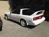
OK, here are some pictures of the real F-40 LM that was crashed to show what a real raced F-40 looks like. Not all F-40's are showroom clean and pristine and this is where my inspiration comes from.
As you can see it's pretty dirty and well used, not a lot of shiny aluminum bits here.

Compare the real one to what I'm trying to do
Back to the muffler now. Pascal posted a picture of one and I found three more; one of which looks similar but, the one I really tried to copy was on a TV show called Fast and Loud. It showed the muffler off the that crashed F-40 on the floor of the garage and it really looked the most like the look I tried to emulate. Here are the various mufflers.
Not quite the color of the other one.
Close but, still not quite it
Almost but, not dark enough
So, here is my attempt. Started with a silver base coat and I put the PE gaskets and brass rings on here.
Unintentional scratches and, I discovered later that I couldn't get the 1mm nuts and bolts on through the holes with them still attached to the muffler so, off they came. That's another story for next time.
Here is the muffler with the silver over sprayed with Alclad pale burnt metal followed with Alclad exhaust manifold on the ends and pipes
It still seemed a little too clean looking so, I decided to grime it up some more
Now it's starting to look like something that's been raced and slightly used and abused like our real F-40
That's where it is now and I'm OK with it I think. It does seem to be following the theme of the engine. I also found a couple pictures of the exhaust system and a turbo as well here. This is off of the LM and you can see the burnt chrome exhaust pipe off the turbo and the various discolorations along the pipes from the header to the end.
The exhaust side of the turbo gets pretty dark from the heat but, the other side stays relatively silver in color. Again, on half of the turbo will be pretty dark and the other side will be aluminum in color but, looking more like the rest of the engine.
I've chosen to build and weather my F-40 more in keeping with a car that gets used and enjoyed on the track. And, doing my research and reading every F-40 with the transkit build, they are all red and super clean. I just wanted something different and, I realize that, it's not going to be everyone's cup of tea but, it will be the only one like it! 😎
-
 4
4
-
-
Thanks guys I appreciate the encouragement. I looked at the Vallejo color and it is very close to what I used. I used Alclad pale burnt metal to start as a base and then put Alclad exhaust manifold over the top of it. I was trying to get it darker on the ends where the heat shield didn’t cover it and slightly lighter on the heat shield itself.
I’ll post those pictures later today with my reference and then you guys will have a better idea of where I’m at. It’s not bad but it just seems like it could probably be better. I really should have Ron living nearby so he could add his magic touch to it, lol 😂
-
Thanks Pascal, I also downloaded a few pictures of the muffler but, more to get a better idea of the color of the muffler after it has been run for some time. To Ron’s point, I am trying to weather the engine parts and I wanted to get a better more realistic look on it.
As I mentioned a while back, I’m ahead of what I’m posting and the muffler is already painted but, I’m not sure that I’m completely happy with it. I have a couple ideas for changes so, we’ll see. When I post those pictures I will also post my reference pictures too so, you guys know what I was going for. I really wish that I could do a few screenshots of the dvd I have. The F40 LM in the dvd is really much more weathered than some of the pictures off the internet. You are looking at a wrecked F40LM and being a race car it better represents the engine as I envision it. I think that there’s some YouTube video of the same car and if I can, I’ll post a link to it with the times in the video that show what I’m looking at.
I’m not sure if I mentioned it or not but, I received the parts from Uli yesterday so, I can get back to the engine.
-
Hi Poul, my cam covers are supposed to be just aluminum. My reference is a dvd that shows the F40 being taken apart from a wrecked F40 and another one that was wrecked too and, they were just plain aluminum. I see what you mean on my pictures though. I think that the flash makes them look shinier than they really are. I’ve also seen the light gray on them too. When I was painting them I thought about painting them the gray but, I opted for just a natural aluminum.
The unfortunate part is that, when the engine is in the car you will probably not even see the front of the engine from the top or bottom. There’s a large vented piece of PE that covers the whole bottom of engine/frame area when done. It kinda makes you wonder about spending all the time to get it correct with the details etc. But, it’s the old “at least I’ll know it’s there “ mentality. Well, that’s my story and I’m sticking to it! 🥴
-
1
-
-
OK guys, here's tonight's update. I started adding the white metal fittings to the turbos and, it was right about here that, I discovered that I was missing the lower fittings. And a quick side note, I emailed Uli on the status of those parts last night and he responded this morning. The parts should be here either by the end of the week or next week.
You can see where the last fitting goes in the turbo at the bottom of the picture.
OK, we pick up with the PE being attached to the muffler
The solder got a little sloppy but, I did my best to file and sand off the excess solder before painting. Oh, and another thing; before I did anything here I used metal etching primer on all of these parts so, when I was done soldering, I at least had some primer on the metal. I used the Tamiya etching primer which, is clear so, it really doesn't show up as anything.
Pretty ugly with the solder and, I did try to melt off the excess but, it really didn't respond as I had hoped. I decided that I would rather just file it down. This solder was a lot harder than I thought it would be; it was more like silver solder than lead/tin.
After some file work. I wasn't overly concerned with the scratches because I am weathering it later on
You can see my notes on the turbo braided lines from the parts manual where I colored the hoses in the drawing. Those were preliminary measurements to get started until I get things mounted and cut them to exact lengths
Preparing the whole assembly for primer after cleaning it up
Primer
First coat of under layer of paint. Got to get the muffler looking more like the engine. BTW, the brass gasket between the plastic muffler halves has a rough texture on it so, it's not a mistake that it looks that way. However, I will take responsibility for the lousy solder work at the ends of the straps where they meet the gasket. 😂
Mocking up the muffler on the engine and it's quite apparent the muffler needs weathering
More weathering on the muffler and the pipes that were cut off next time
-
4
-
-
Thanks guys. Alex, yeah they really bring the model alive and transform what is a diecast toy into a great model. Hey Poul, long time no hear. Yeah, Terrible is moving along quite nicely on his build as well. All you guys should follow what he's doing on his build too!
Just a quick update here; I am still waiting on the replacement parts from Uli in order to continue on the turbos and step 16b. I have the braided lines pretty much ready to go but, I want all the fittings for the turbos before I make the hoses. Once the turbos are mounted or at least mocked up I can measure them exact and finish making each hose end with a collar and or eye bolt to connect both ends of the hoses. I have been working on some small stuff and, I received the eye bolts from Knupfer to go along with the ones I got from Proctor-Enterprises so, now I have 3 different size eye bolts! That's about 20 more eye bolts than I need but, you never know when you will need hardware for scratch building something.
I do have some more pictures to post but, I'll have to do it tomorrow once I get them sized down and ready to post. In the meantime I might just start building some of the other sub-assemblies like fuel tanks or oil cooler radiators etc. When I pulled out all the body parts I found the main radiator that, I forgot that I had put together a long time ago so, maybe a few more things like that can be built while I wait. More tomorrow.
-
2
-
-
Thanks Pascal, good tip on the hex rod and it so happens that, I have some. Thanks Ron, I forgot about best balsa kits. Today I decided to shoot some pictures of most of the completed parts and post a couple from before when the paint was fresh. Like I said a while back, some of the body parts got a little damaged in the containers and I'm going to have to do a some wet sanding on a couple pieces and re-shoot the clear coat. So, what follows are some older pictures and ones that I shot today. I was going to shoot these with my Nikon DSLR but the batteries were dead so, iphone xs it was 🙁
Back in the day
Today's pictures
So guys, that's what has been completed and there are even more things like the radiator and some of the interior where I'm working with the Tremonia interior transkit for the LM version as well as a few resin LM parts like the front splitter and rear wing and things like that. But, for now, I'm concentrating on the engine.
-
5
-
 1
1
-
-
Thanks guys! I have some of the ones that come from MMC but, I think at the time I looked at them and thought that they were too big. I’m going to look at them again today after work. I really should have gone through the Knupfer website when I was ordering the eye bolts and checked to see if there was anything else that I needed. The shipping cost from Germany to California adds up for some tiny bolts not to mention how long it takes to get here! I’m still waiting for the nickel eye bolts. Last night I started playing around with the two sizes of the brass bolts to see which one looks like the right size. I did have to drill out the holes on both though. The stud/nut combo that you referred us to on the Knupfer website comes in a variety of sizes and I’m sure that there’s a more correct option if the ones from MMC don’t look right. But, they sure look good on T’s engine.
What all this shows is that even given the cost and parts count of the transkit, there’s still a lot of extra hardware needed to really get the build more correct!
I really wish I could find a larger size of the aeroquip fittings for the larger braided hoses. I just don’t like having to cut brass collars in half for the ends. They don’t look correct on all the hoses; some but not all.
Pascal, I don’t suppose you have any idea where we can get those do you?? Thanks everyone!
-
Yeah, when I was doing that part of the build I tried to buy these from Marvin but, they were out of the steel acorn nuts and all they had was the brass ones and I didn’t want those. So, I just used steel bolts.
But, actually what I was referring to is the two covers on the back of each head parts D11 and D12 and the little brass stud/nut combo that you used. That’s where I had to use the watch screws. I would probably change them out if I could get what you used. I couldn’t find anything like that when I was putting them on.
-
Yeah my muffler is already finished and painted. Those will be the next pictures that I post. When I soldered the brackets on the straps I got a little too much solder on and I had to file off the excess. I was slightly concerned about soldering the straps to the lip but it all held together fine.
I do have a question about the studs and nuts that you used on the back of the cam covers. Where did you get them? I checked mine tonight and I had to use the stupid tiny watch screws supplied with the transkit. Looking at them, it’s as if I didn’t do anything there because they just disappear.
-
Here's some more on the muffler and heat shield assembly. The bottom brackets get a small nut soldered on the underside for the bolt to thread in to when the muffler gets attached to the rear transaxle bracket
Here you get a better view of the gasket between the muffler halves that the straps will get soldered to
Backtracking a little, I added the bungs on the bolts previously installed. Some reference pictures show two on each side of the header and others only show two on each header. I'm going to have to go to the parts reference and see what it shows. Who knows I might be adding four more.
One other thing that, I've been looking for are a larger size of these and I can't seem to find them; does anyone know where I can find something like a 2.5mm / W3.0mm aeroquip nut like these 1.6/1.8mm / W 2.0mm nuts from Autograph?
-
2
-
-
Looks much cleaner than mine, nice work. I can see the additional hardware from Knupfer that, I don't have. The acorn nuts on the valve covers and small studs and nuts on the rear cam covers and a few here and there on the bell housing etc. I can stop posting on my thread now!
-
I just missed your starting thread when I was posting on mine, I just sort of answered and suggested that you start a your own thread or post on mine if you wanted. But, this is good and we can share notes! Looking forward to your pictures.
-
Thanks guys, great feedback!! I wasn't going to post again until I had the pictures re-sized but, I felt that I had to pop in for a quick comment or two; I will still post the pictures later. First off, good information from Pascal on the eye bolts and yes they are expensive. In my case I wasn't sure of the exact size that, I needed so, I know that I over bought. I'll have eye bolts for every build yet to come, lol. 😩
Welcome Terrible! I'm sure that everyone would love to see your build and progress. I too, have looked at just about every F-40 with the transkit build, in order to try and see what they did and where certain parts go etc. Those, along with the F-40 parts manual have been my best friend lately on the engine build. You should probably start your own thread but, you are welcome to post pictures here too. Originally, this thread was started as a two person build but, it turned into a one person build. Nobody's fault, just life, time, work space and a lot of other things stopped that and then, I went back to work which, has stalled me to a large degree.
SB, I really like your comments and it is the best description of what the F-40 with a transkit build is about that, I've heard! I'm afraid that, I probably fall into the more money than brains category and I feel that, I only have moderate skills being brought to bear on this build. Sometimes, my pauses are due to trying to work things out in my head before continuing on and making a really big mistake. There's just too much money tied up to screw this up. However, I'm pretty certain it won't be a museum quality pristine build when finished. I never intended it to be that. If I can end up with a reasonably well built car that looks realistic then I'll be happy. So, onward and upward; I look forward to seeing Terrible's F-40 and working out some of the instructional issues together. There's nothing like someone else doing a similar build to inspire and push to to become better.
More progress pics later today.
-
1
-
-
Thanks Pascal, I ordered the same eye bolts as in your picture. It was the only size with the long non-threaded shoulder and in nickle plate. I had already ordered two sizes of brass eye bolts and they have a bore of 1.2mm with a 2mm threaded shaft and the diameter of the head of the eye are the only size differences with one being 3.85mm or 5/32" and the other being 3.10mm or 1/8" in diameter. The nickle plated ones from Knupfer have a 1.8mm bore with a 3mm threaded shaft and as far as I can tell the diameter of the head of the eye is 4mm. So, all in all the head size is about the same but the bore is a little larger on the nickle ones. Since the brass is pretty soft, I can always drill out the bore if needed. I am measuring the molded on bolt heads on the turbo fittings so, I can try and get the eye bolts and bolt head replacements as close to the right size as possible.
The T-10 & T-11 brass collar sleeves are what go over the braided lines to create the end sleeve for the pressure tube look. I may have already mentioned this but, I plan on using the eye bolt on the end of the hose that connects to the turbo and just the collar sleeve on the other end. Go back a little and look at post 438 with the parts diagram and look at the green and pink hoses and you will see the hose ends that the eye bolts are meant to replicate.
Tonight, I managed to cut the waste gate pipes apart and I'll be working on those while, I'm waiting on the parts from Uli and Knupfer to arrive. In the meantime, I have more pictures to load up and resize to be able to post that, continue showing the muffler assembly. I will probably get those done in the next couple of days. Even though I'm working ahead, I do have pictures of work already completed, to post so, more to come.
-
Shortly after Pascal's post showing the eye bolts, I started searching for them. I actually found the exact ones at the Knupfer.com website and I found two other sizes in brass from a company here in the US. I have already received those but, I'm still waiting on the the steel versions from Knupfer as well as the replacement parts from Uli at Autograph. I also received the 1mm nuts from MMC to continue working on the turbo and waste gate flanges. I'm still working on those and when I get caught up I'll be posting about that. I really need all the little associated parts for the turbos, pipes and braided lines to finish. In the mean time I have started drilling the holes in the turbos for the fittings and the braided lines haven't really progressed much since last time. I have the muffler started and a ways along now. So, here are those pictures.
I kind of had to guess at the placement of the holes based on the parts diagram and pictures of other builds and the real car
Starting on the muffler by removing the pipes to add the PE flanges and 1mm nuts and bolts
Starting to add the PE to the muffler
The various PE parts for the muffler heat shield or silencer
The two main silencer parts
Bending the bottom piece to shape around the plastic
The exhaust pipes are just there to line up the PE when I glued it down
The top side of the muffler
Bending the PE brackets for the straps. A 1.5 mm nut gets soldered on the under side of the bracket for the bolt to screw into to hold the muffler to the transaxle
The brass strips go over the stainless steel PE as brackets and get soldered to the large flat brass PE gasket. A bit tricky to keep from melting the plastic
As you may recall, I've been rewriting and adding things to the instructions that aren't on the Autograph instructions and this is just one of those pages where I had
typed it up and as I went along, more and more things came up.
On another note, one of our group has asked me to to get out all of the finished pieces i.e. the body parts front suspension, rear frame and the engine progress to date. And, to put it all together, in sort of a group picture just as a reminder of how much has already been done and give an idea of where this is all going. When, I can clear enough room on the workbench and, get the various pieces out of the plastic storage containers, I will do this just for fun. I suppose that, I could also use a reminder of what the end goal is as well. Sometimes, when you are engrossed in all the small stuff, you kind of lose sight of the bigger picture and the ultimate goal.
-
4
-
1
-
-
Thanks Pascal! I’ve never seen eye bolts like these. When you get back home do you suppose that you could share where you can get them and any information about them? They look like the perfect solution for the hose ends. Thanks again
-
SB, I understand about the weathering. The majority of the F-40's with, the transkit, are all super clean showroom new without anything but, an as new look. I get that, and I like those but, I just wanted mine to be a little different. It may not be to everyone's liking but, it does seem to be kind of how they look after some wear and mileage. I've been referencing the DVD called "Back to Life" and the wrecked F-40 on the TV show Fast and Loud. Both were LM versions and had crashed. What I'm trying to replicate is what those engines looked like when being disassembled from the body. These cars were raced and used and abused and, even though the body might be clean, the engine and undercarriage definitely were not. I'm just going for a real life, driven F-40 and, I realize that my weathering skills aren't in the same realm as Ron's Ducati but, who's are. If I can get a close representation of the reference material, I'll be happy.
Pascal, I appreciate you looking into the part number of the detail up kit from Autograph when you get back. You mentioned using an eye bolt and hex bolt; what type of eye bolt have you used? I know that there are some supplied in the transkit for something else and, they are just small ones with a coarse thread that, you would use to screw into a wood picture frame or something like that. Is this, what you are referring to? I know that, you use quite a variety of materials and supplies in doing your scratch building.
For those of you who don't know, Pascal has practically made his own Pocher F-40 transkit out of plastic, brass and everything else, in building his yellow F-40 Barchetta convertible race car. He said that the price of the Autograph transkit was too expensive so, he made his own.
There is a lot of talent here, on this thread and, we all benefit from the discussion. I don't mind if we go off topic now and again as long as we all can get something out of it. There's just too many smart and very skilled guys popping in to not, to benefit from everyone's input.
Thanks guys!
-
1
-
1
-
-
Wow, I didn’t realize that there were that many sold. I knew that some had the OZ wheels but, I didn’t realize that the transkits came in two specific versions. I have never heard of the special kit with the hoses and attachments, this is new information to me. This why some of the assembled transkit F-40’s look, a lot more refined at the fittings on the hoses. I have looked for those fittings and never found anything like them. I always thought to myself, where did that get those parts, did he make them? I’m looking forward to seeing if you can get me the part numbers so that I can ask Uli if he has a kit or maybe some of the fittings left.
He seems to have a stash of parts from the kits left because every time I ask him, he seems to have a replacement for it. I thought that, I would probably be out of luck with the WM41 turbo fittings. And, he said no problem and, is sending them to me so, who knows maybe I’ll get lucky; for a price. lol 😆
Thanks Pascal
-
Thanks for the tip Ron. I just heard from Uli at Autograph today and he's going to be shipping some of the missing parts for the turbo fittings. I think that he switched the casting from white metal to nickle so, they might come out nice. Pascal, your comment really made me think about exact;y what it is that, I'm working on. I forget how many of these transkits were in the initial offering but, I think it was around 200 or so. I know when Rich I and I acquired our two, they were given a special serial number because they were made up of some spare parts that they had left. The demand was so great that he put together about 25 additional transkits; mine is SP 022 so, I got in on the tail end. Anyway, given the low number of transkits and low number of build threads and completed ones, you're right about it being a handful. When looked at in that new perspective, I do feel fortunate to be building this kit. I've known about these transkits for years and always thought of them in terms of the holy grail of kits. I don't think that I ever not thought about building it when I got it. Sometimes you hit a point when you have to let your skills catch up to what you are doing. I've hit that point once or twice along the way hence, the comment about making mistakes. I imagine that, I've probably spent many more hours working things out in my head than I've actually spent on the bench. I have probably gone over different aspects of how to do something 1- 15 times before I hit on the way to get something accomplished. It has been challenging and I guess that's really part of the fun of it.
Continuing on, I added the rear mount for the muffler
A little more work on the top end
Added the alternator
Getting ready for the turbo lines, gathering the materials to make all those braided lines
The wire to strip and make this braided line. There will be six of this size on the two turbos
With the core stripped out of the braid and solder inserted in its place. At this point, I don't know exactly how long to make them and they all have a slightly different connection to the engine.
I need to see all of the white metal fitting to decide how I'm going to attach them to the turbos. This is where I spend some time trying to come up with a good connection that looks realistic.
This is how the turbo piping looks. I don't have anything that looks like the pipe flange on the end of the orange line on the turbo side.
None of the white metal parts allow a connection like the ends of the pink and green lines. I believe the yellow lines are solid piping.
The other reason that the top of the engine is still not complete is because I don't want anything in the way when I make all the connections on the intake manifold area.
Everything is a trade off.
-
4
-
-
Thanks for the welcome back guys! SB, I did look at that link and Goggle translates it into English so, no issues with reading it, thanks. His build seems to have a lot better hardware than is supplied in the transkit in some parts. It's another great build and it is the second that, I've seen on that forum. It has great reference for me to use, thanks. As a point of reference, I'm up to about the end of his page one on the engine and my rear frame is done onto his page two. I am seeing some things that I like that he did and if it's not too late I might borrow some of his ideas.
Anyway, here's a few pictures from a while back.
Remember yesterday when I said that the oil filter housing has been on and off several times? These holes are part of the reason. The water line off the side of the engine goes in the front one and, two turbo water lines go on either side of it. The turbo lines are where the hole that goes all the way through is.
The fitting that's circled on the block is where the single water line starts
The fitting on the left with the red circle is the other end and the parts that are circled are where the braided line connects. The longer pipe with the nut at the end is what goes into the housing on the oil filter
A closer view of the pipe
The next thing was to add the exhaust header head gaskets. Here's an example of where the transkit didn't supply the correct bolts. You get watch screws to put in there, screws don't go there! So, I had to use these bolts instead
I also wasn't paying attention at first but, the gaskets are directional on how they go on
Finally got them all installed with the .8mm bolts
The headers have bungs and I drilled out two hole in each header and installed .080" bolts. Another non transkit bolt
Again, another mistake that, I will be correcting in later upcoming posts
I made a lot of mistakes and had to redo a few things. In this case, I didn't put bungs in, I just added the bolt heads. I also only put two on the top of each header instead of two on the top and two on the bottom. Each header has four which I go back and correct. Anyway, I don't mind showing my mistakes; this transkit is a real learning experience so, there's a lot of doing things over to get it right. Part of what makes this slow going is trying to think steps ahead and taking into account that if I install this part now, will it be in my way in the next step or two steps ahead. I spend a lot of time thinking about whether or not I'm ready to permanently ready to attach something.
-
3
-


Pocher F40 with Autograph Transkit 1:8
in Work In Progress - Vehicles
Posted
I'm glad it helped. I noticed that when I was assembling the radiator it was coming out way too thin and that's where the plastic spacers came from. I have a question for you now. I was looking at your engine pictures and I noticed this oil line circled on the trans axle. I know that, I've seen it before on other builds but, for some reason I don't remember seeing it on the instructions; did I miss it somewhere? I'm also seeing the 3 washers embedded on your header up by the head; I'm pretty sure that's an add that doesn't appear anywhere in the instructions as well, correct? Anyway, keep up the great work!