


ICMF
-
Posts
600 -
Joined
-
Last visited
Content Type
Events
Profiles
Forums
Media Demo
Everything posted by ICMF
-
Currently? Not great. I've run a bunch of normal, supported prints, and the print quality has blown me away. Like, injection moulded quality with just a bit of anti-aliasing. But... I tried to print a simple replacement turbine part on the build plate last week and the Z-axis dimensions were completely screwed up. https://imgur.com/8lUgfmw (original model in grey; actual print dimensions in red) Then ,I drafted a simple stair-stepped calibration model to figure out where the error lay. https://imgur.com/vo12U7l Super simple - each 'step' was 1mm high, so even if the build plate level was off, each step should still be 1mm tall. I tested the model on my Anycubic M3 Max, and the results were as expected - each step was +/- 0.02mm of the expected amount, which is well within the expected margin of error of my digital calipers. When I ran the test on my Saturn 2, the results were terrible. My first 1mm was 1.57mm thick (which is WAY thicker than the actual tramming of the build plate), but the top of the part was only 9.7mm thick, meaning I had actually *lost* 0.87mm over the 10mm. https://imgur.com/Aqpxm4Y No idea where the problem lies, or how to fix it. It feels like it has to be something mechanical - it can't be a slicer setting. since it's the motion of the Z axis that's the issue. I guess my next step is to print a taller calibration piece, to see if the error eventually zeroes out after 20 or 30mm. And wait until Elegoo get back from vacation to hopefully help out.
-
Yay! My Saturn 2 has arrived! Upgrading from both a Phrozen Mighty (for the bigger size) and OG Photon (for the higher res) I haven't been able to run it yet, but resin printers are kind of commodity products at this point, so barring any major design flaws, it should be fine. A few thoughts for those who are interested: Like: Power switch is on the front of the machine. Nice for multi-printer setups and just generally more ergonomic. Lid "pre-drilled" with hole for vent fan. There's a moulded in hole (with screwed on cover) for a ~70mm PC fan to help vent the machine. Those that want to add extra ventilation won't have to mutilate the lid. Vat has max fill indicated. Simple but handy touch. Vat has handles. Pretty much a requirement at this size. Vat has feet, protecting the FEP when you set it on a workbench. Simple solution with four thicker cap-head screws, but it'll save scratches/damage/punctures. Build plate is a positive fit. Handy if you have to remove and reinstall the plate mid-print for some reason. Plug in charcoal filter. The printer has a USB socket on top *strictly* for plugging in the included filter. Easier than using one of the battery operated filters, but DO NOT PLUG IN OTHER USB ACCESSORIES. No-Like The vat screws are too long. They thread about 1/2" into the printer, so they'll be annoying to screw/unscrew. The power button is a momentary switch. It takes about a second for the screen to light up, so there's a bit of "did I press it hard enough or not" uncertainty when you turn it on. Tape around screen. Elegoo have applied a tape/gasket to seal the screen from resin leaks, but the cutout is actually smaller than the build plate, which makes levelling... confusing? Narrower tape or a thinner build plate (it's larger than the screen) would help. Meh. (not a fan, but not a big deal) The design. It's a little Transformers, IMO. I'd be good without the angles. USB socket is at the rear left. I'd much prefer it to be at the front, but it's easy to fix with an extension cable. Pouring lip on the vat is in the top left corner (or else max fill line is in the wrong location). Bit of a nit, but with the fill line visible, I'll have to rotate the vat to pour resin out of the spout; with the spout in my preferred location, the max fill is at the front of the printer, and less visible. Ball jointed build plate. Not a huge fan of Elegoo's levelling system, and with a plate this large (10"), it would really benefit from four point levelling. Solid feet. These are moulded into the chassis. I'd prefer to have adjustable feet, so I can level the printer itself. Plastic chassis. I honestly don't care - it's sturdy enough for a resin printer - but some people will complain.
-
 Bah. You're never too old. (but yeah, I get it. build whatever makes you happy.)
 -
Well I can answer the spool part, at least: it's 'detail 1' in the scale drawings (the cylinder under the upper wing), so... about 21 x 1050 mm. Be proud. CAD offers the advantage that size doesn't matter - I can zoom in and add microscopic details as easily as anything else. That's not true of scratchbuilding - sway braces are a pain to detail! I won't be selling the files, but if there's interest, I will make the kit available. Being an experienced scratchbuilder, you should have a big leg up in learning CAD, if you ever choose to do so. I think one of the biggest hurdles is being able to break complex objects down into simple shapes - seeing a busy cockpit as a series of circles and squares, for instance - so if you've got a handle on that, you're a long ways towards understanding how to think about designing parts in CAD. After that, it's "just" learning how the software works. Not saying it will be easy, but certainly easier than starting from zero.
-
I'll put you out of your misery: it was fly by wire. https://en.wikipedia.org/wiki/Siemens_torpedo_glider
-
Small update. Since the plan (at the moment) is to finish it as a late-career test ship, I needed something cool to dangle underneath. That means SSW torpedo gliders - one of the first "precision" air to ground munitions. Scale drawings were imported into Solidworks, then scaled and traced (the measurements are very helpful here): And the CAD model completed. Same process as the Zeppelin - various bits were extruded, revolved, cut, shelled and filleted to shape. I can do a detailed breakdown again, but you probably get the gist: Designed in 1/144, currently printing in both 1/144 and 1/72. And for anyone wondering, it's about 50mm/2" long in 1/144.
-
Ditto. I'm really anxious to get my new printer. 😁
-
Glad you're enjoying it. That was a big part of my goal in the thread - to show what's involved in designing and printing a kit. Lots of people talk about and are interested in 3D printing, so I thought a thread that (hopefully) explained the nuts and bolts would be useful. Oh, and look forward no more! Success! (mostly). All the parts turned out well. Had a bit of trouble with the first cm or so of the prints, so they're a little wobbly - not sure why, but it might have been due to mixing resins in the vat (had a bit of older, grey in there, topped it up with a bunch of clear). Ah well, it's certainly fine for a test run, and bodes well for any future 1/350 prints of the model I might want to do. (hint, hint :D) Close up on the tailplanes, showing the nice, subtle ribbing. It's a little more opaque than I'd like - I used a clear resin to play with the translucency if/when I get around to painting it. Even the fine door framing rendered well. Not as happy with the gondolas. They're a bit meh, and I'd reprint them if I wanted the model in this scale, but still... you can see the ribbing on the sides of the gondola, and the hollow windows/interior. Bit of a step up from Takom's parts. Tailplanes rendered nicely. Sharp, crisp detail. And SUPER thin trailing edges. Again, a nice detail improvement over Takom's parts. Penultimately, a close-up of the envelope, showing the post-print surface. I haven't done anything more than cure the print here. Pretty much ready for a filler-primer, IMO. Might need the slightest rub down with some 0000 steel wool, or similar. The coolest thing about resin prints, though, is that you can use the same resin to join parts. Just a tiny smear of liquid resin, hold the parts in position, then give them a slight blast of UV light and they're cured as solid as the rest of the print. It's even more instant than CA. So of course, I put this to use, and a couple of minutes later...
-
Glad someone gets it. So, another update. I figure, whilst waiting for my Elegoo Jupiter (hopefully arriving in May?), I might as well scale things down and print it in 1/350. It's pretty much just a direct scale-down - I made the envelope itself thicker so it would be rigid, but I haven't played with the 'rib tape' dimensions or anything - so it'll be interesting to see what prints and what doesn't, but it *should* be okay. Step 1 in print prep: add vent holes to the envelope. I'm using a resin printer, which uses a vat of liquid resin over top of an LCD screen (like a cell phone or tablet screen); a UV light shines from underneath, and the LCD screen masks off everything but the outline of each layer. A metal build plate comes down from above, the first layer is exposed and sticks to this, then it lifts up to peel that layer of cured resin off the the vat, then lowers back down to expose the next layer, repeating this cure, lift, lower pattern. This is important because, if you've got a hollow tube, it will create a strong suction force as the build plate raises and lowers. Like lifting an upturned mug out of a sink full of water. The way to solve this is to add an air hole at the top (or bottom, depending on your perspective - closest to the build plate) of the part, so that air and resin can freely flow in and out as it raises and lowers. As an added benefit, these air holes serve as alignment points to help assemble the completed envelope. Next the envelope is chopped into individual sections. Again, you can see the vent hole I've cut in the part. Smaller items like the tailplanes and gondolas are prepped for print, with pour stub-like supports. I could add individual supports in the print software (you may have seen the forest of rod-like supports on other 3D printed parts), but felt this would produce better results for these parts. Then the parts are all saved in a format the 3D print software can read. And opened in said 3D print software. This converts the various 3D models into individual layer slices. In this case, it's basically a whole bunch of JPEG files stacked on top of each other, with a little bit of machine code to tell the printer how long to expose each layer, how fast to raise and lower, etc. I've doubled up the gondolas and tailplanes because they don't take much resin, and being smaller, they're more prone to failure. This way, I'm more likely to get a good print. (now watch the biggest envelope part fail...) And then the models are converted for printing. The left side shows the printer's build plate at a particular layer; the right side shows what the LCD will expose for that layer - in this case, layer 145 of 3001 total layers, or some 12 hours total print time.
-
It'll be about 110 cm, or 44" long. Bit bigger than your average 1/144 fighter.
-
Okay, moving forward... I thought I'd do a deeper dive into the construction of the gondolas. So here's a bit of a step-by-step. This is just the processes involved; every process involves at least one sketch, which is the time consuming bit as you try to interpret the references and make an accurate part. These sketches and processes tend to layer on top of each other, so if you find out you did something wrong earlier in the design, it can break subsequent steps, which means you've got to go back and repair things, so it can be a tedious process. Tl;dr: it's not as easy as it looks I decided to start with the main windows. You have to start somewhere, and they seemed like a fairly central detail to 'hang' subsequent operations on. (hard to see, but) next is a loft underneath, to blend the main, square section of window with the bottom of the gondola. Then the front bottom of the gondola is extruded with a slight taper. ...and cut to shape. The mid section is extruded from the roughed out front section. And the various sketches completed so I can create a loft for the aft end of the gondola. The cross-sectional sketches form, well, the cross-sections of the loft, but they have to be told where to go, or else they'll simply take the straightest path (or occasionally, a random, wild path...). This requires additional sketches floating in space, to connect the cross sections. It's actually a bit of a process to create these - flat planes are simple to trace, but sketches that are fully 3D end up requiring a ton of preparation and tweaking to perfect. I'll often extrude, cut and loft temporary bodies so I can trace their (3D) outlines to get the necessary 3D sketch... then delete the bodies and use the resulting sketch to guide the loft. All that prep work done, the loft is completed. I only did one half as it was easier to force the loft to do what I wanted. I can mirror it later. The roof is then extruded... ... and the entire model gets chopped in half. This wasn't my original plan (or else I'd only have done one side of the front section) but after screwing around with the loft for a while, I decided it was the best option. Doing two lofts side by side ran the risk of causing problems meshing with the rest of the model; mirroring just the loft might have worked, but in the end, cutting it in half gives me a single, flat surface I can use to mirror the other side, for a simpler construction. It boosts the file size a bit, since it's more process-intensive, but I felt it was worth it. Mirrored. The final step to rough-out the gondola is to create a loft at the front of the roof. This is a great example of using sketches to 'force' the loft into place - I'm trying to merge a triangle into a weird, six-sided shape. Each of those grey lines tells the loft to go from point A to point B. Without them it would fail, as it can't reconcile the the 'start' and 'end' sketches. [img}https://i.imgur.com/GYeZpzd.jpg[/img] And the gondola is roughed out. This completed body is then duplicated so that I can add details. One body is hollowed out to create the main part of the gondola. The other body is shelled outwards, adding thickness, so that I can model the raised surface details. Here you can see a portion of the outward shelled body cut away, exposing the window area. The ribs are then cut out and merged with the main body. I now have raised ribs on a hollow gondola. Time for some windows. The rear, open section is cut out. Front windows are recessed. Front windows are then cut out. I've left a .25mm lip around each pane to fit a piece of acetate, once printed. The left side's windows then get mirrored onto the right, and the front window is cut out. And the side windows are done in the same manner. The access hatch is cut in the roof. Incidentally, most Zeppelin kits seem to include this as a 'tube' between the gondola and envelope; this doesn't seem to be correct, from my readings. As far as I can tell, it was open there, so you'd get a blast of icy air traversing the Zeppelin. This solid bit is added. Not quite sure what to call it - it covers the connections between the gondola and the airship. Finally, the rear bumper is added and the gondola is complete. I'm probably not going to detail the interior of this one; you really can't see it on the finished Q class, so there isn't much point. Phew. And THEN, I did all that all over again, for the rear gondola! And with THAT done, I could start buttoning up the envelope model. A new assembly was created and the scale drawings were turned back on, to help with locating everything. Note that, after correcting the section spacing, the model no longer lines up with the scale drawings - they're wrong, mine is (more) right. Hence the slight discrepancy. The gondolas are imported and lined up. I can now make location holes for the struts, rigging, access hatches and such. Like this. They may not fully print, but the holes should at least give me a slight recess as a location point for drilling. Next up: completing the gun platform, then prepping all the individual parts for print. This is about where my enthusiasm wanes, as I'm still waiting for my large-format printer; the itch to wrap my head around the shapes is mostly scratched, and I'm stuck twiddling my thumbs. Oh, and as a particularly annoying kick in the balls... a different company has announced ANOTHER large-format printer, which is a whopping 1cm bigger, should be available sooner, and only slightly more expensive. That 1cm may not sound like much, but it's JUUUUST enough to print all of the height climbers.
-
Just remember, you can do a reasonable job bridging in FDM, but you can't really bridge in SLA - at best, the first layer is a floppy film of resin that's half the thickness of a sheet of paper ; at worst, it'll be a floppy, thin film of resin that simply tears off the part, sticking to the FEP. This is the 'tentpole effect' - it's like a sheet of fabric being held up by tentpoles, sagging in between them. This is why the surface facing the build plate is never as crisp as the surfaces facing away from it.
-
Unfortunately, you can't just magic up any shape you want with a 3D printer. You need to design for the medium. The steps I'd take to troubleshoot, from least to most work/lowest to highest chance of success... Calibrate your resin with a RERF to find the best exposure time. Print the file straight off the build plate, if you can, rather than using supports. Add a ton of supports under the overhangs. These areas will never be perfectly flat, due to the 'tentpole effect', but the more supports, the closer they'll be. Add a hole to the side of the stacks. As it is, you're printing suction cups; a small hole in the side will allow airflow and eliminate the suction. Thicken the thin walls at the front and back of the model. Adding supports to their sides for lateral stability will also help. Consider revising the model, to remove the thin, flat overhangs. You could easily skin these areas with styrene sheet instead. This would get you closer to your original design.
-
Next, attention moves to the tailplanes. These were sketched out, then more complete detail drawings made, before the actual modelling was begun. First, the framing is extruded: Then the 'fabric' is extruded - slightly thinner than the framing, to give slight relief. Then various details added - the rudder trailing edged were chamfered to a thinner edge, fillets added to the tailplane leading edges, control horns(?) added, etc. And the same process was repeated for the horizontal tailplanes. The envelope was copied, then a thin shell is created as the basis of the framing detail. The frames were then marked out and the areas between cut away from the shell, leaving a series of thin 'rib tape' rings, which are then merged with the original (correct size) envelope: And finally, detail areas were cut out from the almost-complete envelope: windows, the gun platform, rigging points, etc.
- 19 replies
-
- 12
-

-

-
Sooo... how to design a model kit. The first step was to scan the scale drawings, re-size them to the correct scale dimensions, then carefully trace the key dimensions - the outline of the airship, location of the tails, gas cell locations, etc. This is a fairly slow, tedious task with a lot of time spent fretting over fractions of a mm (mostly needlessly) and wondering which side of a line to trace to. This process also serves to get the gist of the shapes into my head. It familiarizes me with the intricacies of the subject and just generally helps me get up to speed. With that done, the actual design work can start. A cylinder with the diameter of the envelope was extruded for the nose, then excess was cut away to form each individual facet. The same process was repeated for the tail. There's also quite a bit of cross-checking with the scale drawings and with reference photos, to ensure the creases are formed in the right locations - it's not just a simple 17-sided structure. ...and then a simple loft in between the two sections to finish the raw shape of the envelope. With that done, I turned my attention to the keel, creating a loft to form the front end: ...then the back... ...then the transition sections... Before completing the centre section: Which seems fairly straightforward, but required a bunch of planning, tweaking and revision. The loft tool is powerful - it can make complex 3d shapes - but it's also kind of dumb and doesn't always do what you want it to. It needs to be able to connect each vertex - each 'point' - from one sketch to a matching point on the next sketch. Try to loft a square into a triangle, for instance, and things can go haywire.
-
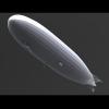
I'm currently awaiting delivery of a large format resin printer, so while I wait, I've been designing another Zeppelin model to print on it: Z XII. Z XII was one of the first Zeppelins built during the Great War and the only N Class Airship. As an early war design, in many ways it bridges between the pre-war passenger airships and the war time bomber/recinnaissance airships. It introduced changes such as the duralumin structure and central keel, but maintained the external keel gondola of the passenger airships. The gondolas were enclosed, with the front using a pusher propellor for the first time, while the airship lost the venetian blind-like array of tailplanes for a simpler, cruciform tail structure. It had a successful career spent mostly on the Eastern Front, before being retired to training and development and, astonishingly, managed to survive the war. It was the first airship to bomb Paris, the first to use an external 'sub-cloud car' for navigation, and it was the first aircraft to use a standoff guided weapon: the Siemens Torpedo Glider. This is how I plan to finish my build, in a late-war sheme with dark envelope with a lighter top section, and a pair of torpedo bombs slung underneath. ...as seen here, which also happens to be my primary reference, using the excellent scale drawings contained therein. The volume covers the history of all the early Zeppelins used in the war, with special focus on Z XII and the O Class ship LZ39.
-
For early war, doped linen finish: Post-war 'silver' Zeppelins were... not silver at all. They used a natural linen with tiny, blue dots printed on it, which appears silver from a distance. The late-war height climbers used this printed linen on the upper surfaces, with a black finish daubed on the rest of the envelope.
-
Very nicely done!
-
Depends what look you're going for. If it's a super realistic, detailed build, I'd add the rigging. If it's a simpler, more OOB looking build, maybe not. You want something that's visible but subtle, which is why I actually replaced the monofilament with elastic thread - it was too clunky looking.
-
If I might hijack this thread back to the OP for a minute... Zeppelin Rigging. It's not really complicated - it's a simple pattern that's easy to wrap your mind around once it's laid out - it's just that there's an awful lot of it, and it's kind of hard to see past the spiderweb of lines. There's basically two ways to look at it, but they both amount to the same thing: there are six anchor points along the tailplanes (call these 1, 2, 3, 4, 5 and 6) and six corresponding anchor points along the envelope (a, b, c, d, e, f). The rigging lines run from each tailplane 'point' to each envelope 'point'. So depending on how you want to look at it, each individual tailplane anchor fans out to each of the envelope anchors (the red lines below: 1-a-1; 1-b-1; 1-c-1...); or each individual envelope anchor fans out to each of the tailplane anchors (the green lines: 1-c-1; 2-c-2; 3-c-3...). Same thing, just depends on how you want to run the lines. There is also a set of tailplane bracing lines that run directly between each tailplane, sort of like a series of 'rings' around the tailplane. (1-1-1-1; 2-2-2-2; 3-3-3-3) A couple of practical notes on the process... I made small wire eyelets for my envelope mounting points, and was able to run a continuous length of elastic rigging line for each "section" (wrap the rigging around some ultra-fine wire and CA it in place as a needle). It's not structural like a biplane model, so elastic thread is fine - I'd recommend the finest stuff you can get from Ifini or Uschi. And most importantly, START FROM THE FRONT, AND MOVE AFT. If you start from the back, you'll have to thread UNDER your existing lines, and that's just a massive pain in the bottom after a while. The whole process isn't hard, it's just a little tedious. It's certainly easier than your average biplane rigging job, but it looks impressive as hell when it's done because it looks like a maze of lines. I actually did it three times on my 1/144 scratchbuild - once 'backwards' in monofilament, a second time in monofilament when I realized I had a couple of crossed lines, and then a third time in elastic when I decided the monofilament looked too heavy. Learn from my mistakes.
-
If you're looking for a specific colour match, the short answer is ¯\_(ツ)_/¯ Nobody really knows. That said, there are a few general guidelines. Zeppelins were covered overall in clear doped linen. This faded rapidly in the sun, and regularly had sections repaired/replaced over time (airships required an immense amount of service and were regularly stripped down for inspection and repairs). Additionally, the upper, centre section (the dark bit on the box art between the front gondola and tail) was undoped and made from a looser weave fabric to help vent excess gasses from the individual cells. (these sections also had a 'striped' appearance, but that's way more trouble than it's worth at this scale) Also, the vertical strips between cell sections also appeared slightly darker than the base linen. The box art seems to be kind of depicting this - doped linen for most of the airship; darker section for the open weave - but has lightened the upper surfaces to make it more '3d' (top is in the sun, so lighter, underside is in shadow, so darker). So theoretically, it would start out a more or less solid natural linen colour over most of the airship, with a darker, more translucent patch on top, in the middle. Over time, this would deteriorate to a more patchwork appearance as panels and sections of linen were replaced, leading to a rather blocky look over time. And FWIW, having build a large Q-classe Zeppelin, it really needs that subtle patchwork effect to break up the surface, as it just looks flat and lifeless as a solid colour. Your Zeppelin would then have had the camouflage colours added over top of this base.
-
1/72 - SOKO Yu Supersonic resin kit by L&M Scale Kits - released
ICMF replied to Homebee's topic in The Rumourmonger
The kit definitely is. The 'real' thing (since it looks like it was never more than a windtunnel proposal...), not so much. -
I guess square would be slightly preferable, but ultimately it doesn't really matter. Honestly, of the three of them, I'd probably go with the Mars 3, for the availability of replacement parts and software flexibility. But it really is a toss up between the three; they'll all work fine, they'll all work about the same, they'll all have pretty much the same challenges and learning curve getting up and running. Just pick one and pull the trigger.
-
Available on Aliexpress. I just got an order of 20 scrapers for about $5. https://www.aliexpress.com/item/1005002327779072.html?spm=a2g0o.9042311.0.0.66254c4dtQBIdw The one that comes with your printer will eventually wear out, and it's really handy to keep some in stock for mixing resin in the vat, easing failed prints off your FEP, scraping excess resin off your build plate, etc. You can get them faster through Amazon, but these are super-cheap and exactly the same thing that comes with your printer. The only down side is that delivery takes a month or two; I'd suggest getting some ASAP, so you have them before you need them. Not affiliated, blah blah blah.
-
It doesn't really matter. They're all going to be fairly comparable. The higher res printers (you'll want to go by pixel size, not resolution) will offer a slight improvement in detail, but it's going to be pretty minimal and certainly not make or break - most people will struggle to notice a difference. The only real differences I'd note: Phrozen is based out of Taiwan, not China, so doesn't have the same subsidized shipping as other brands. This means replacement parts can be pricey. (it's also a less popular brand, partly because of the higher shipping costs, so parts are a little more limited) Elegoo's build plate mechanism is, IMO, not as good as Anycubic or Phrozen. It's a simple ball joint which seems a little harder to secure and a little harder to maintain... though realistically with proper care, once the build plate is trammed, you shouldn't have to do it again. Some Anycubic printers are more limited in their firmware, as they lean more on their own slicer. So you can't do some advanced features, like anti-aliasing (which smoothes out curves) or layer compensation (for better geometrical accuracy). I know the Mono X is; not sure about other newer printers. But in the end, you can pretty much just flip a coin. Maintainence and reliability will be pretty much the same for all, and are more a factor of the end user than the basic printer anyway.
