


BS_w
-
Posts
481 -
Joined
-
Last visited
Content Type
Events
Profiles
Forums
Media Demo
Posts posted by BS_w
-
-
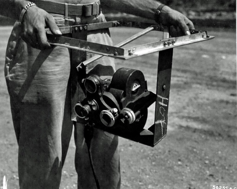
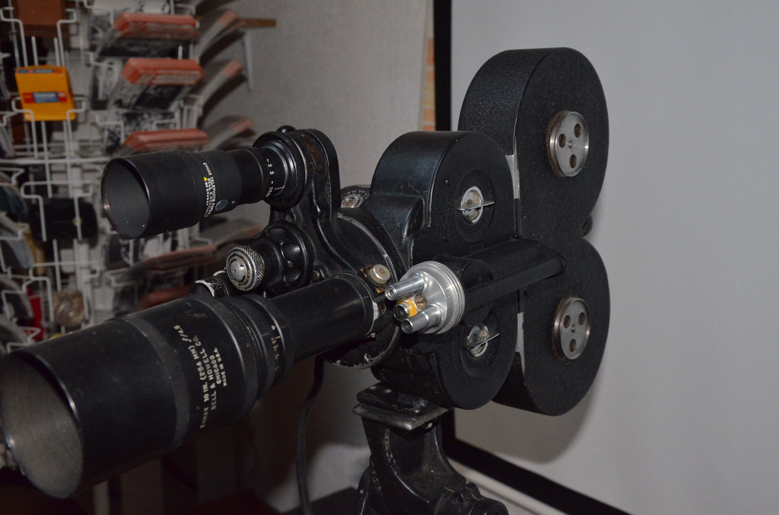
On 2/17/2024 at 4:22 AM, don f said:

It's Bell & Howell type A-3:
Electric motor driven
-
 2
2
-
-
17 minutes ago, Dave Slowbuild said:
Incidentally, regarding the windshield, the Airfix clear part has a pair of faint lines which would tempt the unwary into painting them as part of a frame; now I am aware of this trap I shall leave them unpainted, or sand and polish them out, to be decided…
these two lines are the joint of 1/4"glasses and just behind, lined up to them there were the tie rods(3/16 dia) which maintain the top and bottom frame-
1
-
 1
1
-
-
18 hours ago, Dave Slowbuild said:
ssuming this is the case, which of the two holes in the glass (and therefore which filler cap)needs to be removed? I'm afraid I don't know which is the fuel cap and which is the oil cap...!
I haven't seen this feature in any other image of a P-40 (including RAF Tomahawks) so I am curious if it was a standard production fit, or perhaps a short lived trial.
Dave
Sorry, I'm wrong(fail memory) about the fuel cap on early P40 , Dana give the good response, fuel cap was on fuselage just below the port rear window
-
3
-
2
-
-
Effectively, there were no vertical frame
On P 36 and P40, up to P40C, the windscreen was an assembly of three piece of non shatterable glassmaintained together in top ans bottom frames assembly by two rods screwed.
the joints between the glasses were filled with glue.-
3
-
1
-
-
I would add wing guns (one per wing) had their ammo access on upper surface of wing and fuselage guns were long model(the short type
was made by cut off the forward end of these tube at a 25° angle, from 7th jul 41) and there was one hole only in the rear window for fuel cap,
the oil cap acces door was on the frame aft the glass-
2
-
-
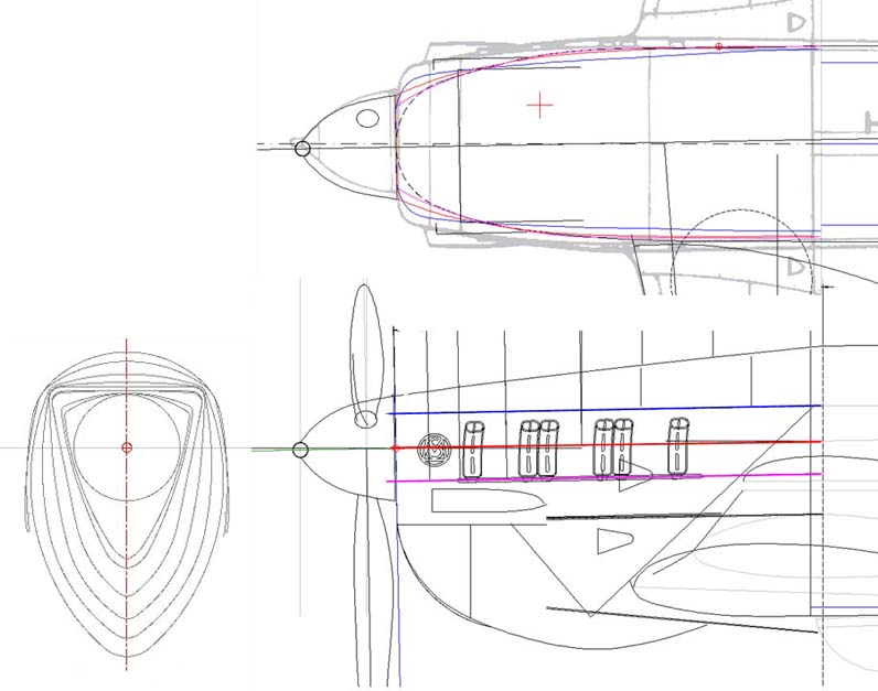
the guns are aligned according the convenience of place in the wing. they are not on horizontal plan nor in the airfoil chord
gun diagram
-
4
-
-
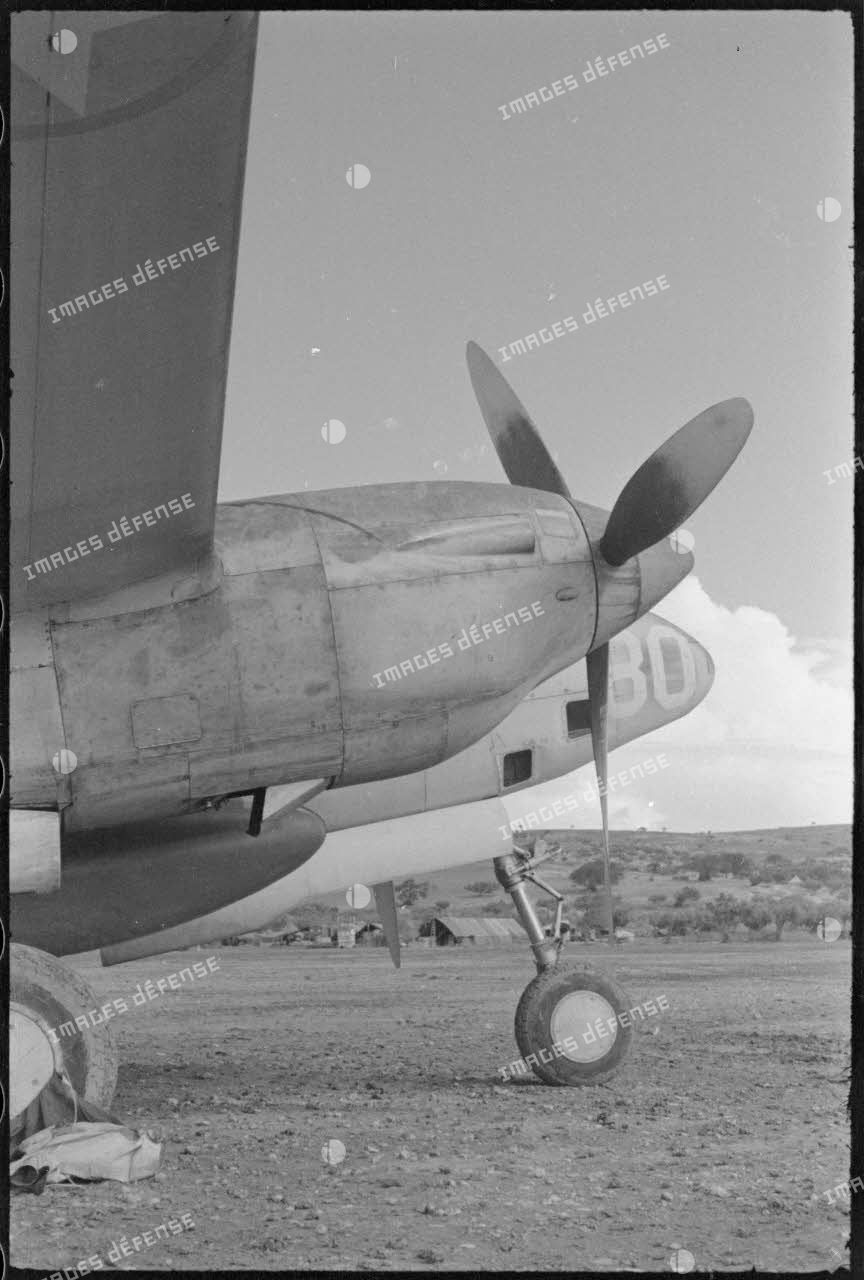
https://imagesdefense.gouv.fr/fr/catalogsearch/advanced/result/?keywords_ids[0]=7744&p=2
link above, where you can see several other pics of "80" at different period and others french F5A and B.
the number and color of mission markings , "camera stylized", were different also.
at the beginning there were 9, in single color(red, black?), then these 9 symbols are painted in blue/white/red and there are 5 halves added, at the last the amount was 15 entire symbols b/w/r.
may be these last markings where added especiallyfor photo reporting on St Ex
is " Jeanne" added by the french or written by U.S crew , unfortunately on the pic the engine mask this nacelle area but there was not the dark crossed markings below the "80"-
1
-
-
"80" with U.S insignia under starboard wing, when she just delivered to french group.
insignia seems yellow outlined, without bar.
-
3
-
-
"yellow green" interior french Hawk N° 223(?) , firewall to frame 3
this primer was common to "Export Hawk" (spec Curtiss S-517)
yellow green was applied over prussian blue Lionoil shop coat.(which prevent scratches on surface of Alclad Skin).
-
4
-
2
-
-
baille lemaire GH 38 gunsight on A1 to A3 and below, british gunsight on A4
Instruments panels A1, A2, A3 & A4 french Hawk (pic from EMM of each models)
-
2
-
1
-
-
from factory drawings, HTH
-
1
-
-
their location was not the same depending on the model;
Sometimes the red light was near the bomb door -
MS 405/406 , 1937/38 (EMM MS 406, finish)
ms 405 / MS 406 received kaki on upper surface and gris bleu clair on under surface.the delimitation between kaki/gbc is straight along the bottom fuselage longeron from wing trailing edge to stabilizer leading edge
38-39
, the délimitation is wavy (short wave) (MS 405 seen at Chartres)MS 406: dec 39, a nota was introduced(MS factory camo & markings drawing):
upper surface will be received gris bleu foncé and brun(chocolate) blotches over the kaki. the delimitation of colours was blended by overspraying
delimitation with undersurface bris bleu clair was straight.
these blotches must be differ from an airplane to other.-
5
-
6
-
-
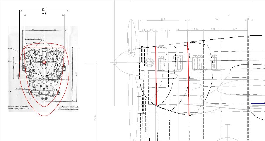
I use a wrong word in place of camshaft casing - sorry-
the MS 405/406 engine angle settings are
- 1° down
- 1° 26' leftfor the airfoils I have the data for all the ribs, I'll look at,
-
3
-
2
-
-
blue line: horizontal section at crankcase cylinder
shadow lines is wrong drawing found on all publication
in red: wide according original MS data
-
2
-
4
-
-
it seems on Late 298 that anchor is painted in white area of fin flash rudder and in the blue disk of wing roundels
At this period the anchor insignia had a rope which was deleted after war
-
2
-
1
-
-
1936:
"An anchor will be painted in white area of rudder and roundel" .
size and design no defined
-
1
-
-
the seat (frame, canvas and cushion) was entirely "night blue",
the shoulder straps go through the backrest
HTH
there is a project for a new D520 model kit at 1/32 scale, the 3D begins soon......
-
3
-
2
-
-
2 hours ago, dragonlanceHR said:
Don't forget that the nose is bent to the left and that reduction gear housing returns the prop and spinner back to paralel with the centreline.
the reduction gear is straight, the prop axis is parallel to centerline engine, so the axis is 1° left-
1
-
-
the offset asymetric airfoil was used also on french MS 540 project and on swiss D 3802/3 build.
-
1
-
-
E-wing, the .303 door with aperture are
replaced by door without aperture which carry a nameplate:
"WARNING
aircraft must not be flown without either guns or fabric patches over tunnel"
on early a/c, when the guns are removed the ejection holes are closed by fabric patches double thickness
-
2
-
-
Havoc I & II, & Boston III : 3 crew , the rear gunner could move upper to lower
Boston IV : 4 crew, there was two rear gunners, upper(turret) and lower
-
P36(H75) & P40(H81) export airplanes, Curtiss specifications S-516 & 517:
5. DETAIL REQUIREMENTS:
5.52 Interior Metal Parts and Surfaces: the finish for interior(unexposed) parts and surfaces (wings, fuselage, control surfaces) shall consist of one of the following schemes, unless a specific scheme is specified in the contract.
- 5.521 All alclad 24ST used as skin covering for wing, fuselage, tail surfaces, and other parts fabricated in the heat treated conditions to be coated both sides with blue Lionoil shop coating, or equivalent, prior to fabrication and assembly.After assembly all Lionoil exposed on exterior to be removed to leave natural alclad as the exterior finish. Lionoil to be left on the interior.
....
....- 5.525 The interior of the entire fuselage, and parts enclosed therein to be given one coat of the following mixture to produce uniform and satisfactory appearance:
COCKPIT COATING FORMULA
One gallon zinc chromate primer
one-tenth gallon black enamel
Two gallon of Toluol
4 ounces aluminium pastebelow, French Hawk 75 A3
-
1
-
-
the midnight blue was used for cockpit interior only(between frame 3 to 5 -from instrument panel to the backrest),
Under the rear vision windows the area could be painted gris bleu clair
or "natural finish", (duralumin sheet was coated with clear varnish on both side before assembly).
-
1
-


Spitfire Mk.IX Pneumatic System Schematic - Help
in Aircraft WWII
Posted
HTH