hi guys,
so I figured I would join up and make a thread on this one so progress can be monitored by the person who's asked for this to be done.
I've been asked to make a model of a spitfire and a messerschmitt in a dog fight. sort of like a diorama. I haven't done this sort of work before so its going to be an interesting journey for me. Due to personal circumstances I'm starting modelling all over again which means I have to get all the equipment again from the very beginning so this build is going to take some time. Now what's lucky for me is I actually live within 5 minutes drive of the manston spitfire and hurricane museum which thank god I can go there for specific information
that will become apparent soon.
I've been asked to make the navigational lights on the planes a functional aesthetic to the model, as well as making the guns/cannons "glow" as if they are overheating and cooling down. so the first part of the thread is going to largely be based around that aspect.
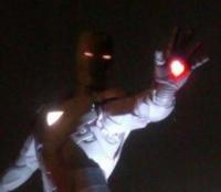
electronics people! integrated circuits, custom code, leds and fibre optic strands, all coupled with modelling. what's not to love?! thankfully I'm not a complete stranger to adding custom electronics to models, if you look for secretreeve on YouTube you'll see my USS voyager, battlestar Galactica, iron man armour and the start of a Galactica fighter I never got to finish. Those where back in my
days of analogue circuits, now I've been able to develop code that I can load into an IC and control things alot more precisely, add "phases" so in star trek I can add a "start-up" sequence, impulse mode, warp mode and even a visualised "self destruct" by "overloading" all the lights as if its just gone boom.
This isn't so advanced, I've deconstructed the original code I had and made various modification so its usable for this instead. the original code was designed with being able to do that in mind so its very versatile and can be used for all kinds of kits.
okay so there's the build up, how about some specifics?
the actual circuit I'm designing has to be small enough to fit within the fuselage of the planes as well so I'll be mounting the leds onto the PCB and transferring the light to where it needs to be via 0.5 and 1mm thick fibre optic strands. this also makes getting the light to where it needs to be alot easier when your dealing with space issues (in-between 2 half of a wing for example?)
yeah, I gotta make the circuit myself, so considering its got a program to run I need an IC chip circuit.
hmm component list? OKAY!!!
through hole PCB board.
atmel ATTINY45 IC
8 pin dip socket
2n7000 mosfets
1/4w 100ohm resistors
1/4watt 150ohm resistors
1.8mm leds of various colours as needed (some are still to be confirmed)
micro USB socket for power inlet
0.5mm diameter fibre optic strand
1.0mm diameter fibre optic strand
I haven't actually settled on a layout for the circuit yet, there's many options but I need the actual plane kit in my hands so I can dry fit the circuit, stuff it in the plane and see which works best for space ha-ha. I'm placing a huge order for components and the spitfire mkV5b kit from tamiya on Friday so next week I'll have plenty to do.
so what's the need for this program? well, when plugged in and turned on, the various navigation lights have to start and be as accurate for the timing on them, this is definable within the program, any internal cockpit illumination needs to happen, and the guns/cannons have to glow.
so the sequence is this, cockpit panel lights up, navigation lights light up and do what they gotta do, the guns will fade up and down at varying periods to indicate overheating and cooling down. And that happening repeatedly at appealingly random intervals.
okay okay doesn't sound very impressive at the moment. but when all the components turn up and I get a prototype working it should make more sense and look more impressive than it sounds. but with the program I can set the brightness level of each led, be it a fader, flasher or statically on. Why do I wanna do that? well if it was on at full brightness it'd be the real life equivalent of the sun behind a fuel gauge. not very realistic. I'll be using my arduino R3 as an AVR ISP programmer for this and to do all the prototype testing as its a pretty robust platform to test this
kind of thing out on.
funny thing, I can do that stuff as realistic as possible, lets see how the paint work comes out shall we? hahaha.
so what's a circuit like this cost? well its about a tenner for components, so realistically, with research for accurate timing and labour and coding as well as assembly, probably a good £40 worth if I was to retail them as a kit which I'd probably do quite happily as used to build up the lights for my Galactica and voyager and sell them as installable kits. without a power supply that is. oooo now there's a point. POWER!
the circuit is designed to run on a 5v power supply, so if you was so inclined, and I wouldn't recommend it but would recommend a stabilised 5v supply, use your phone charger to power the model. I'll delve into that at a later point.
"okay okay so enough text show us some pictures or something!!!"
here's the schematic I doodled up using MS paint.
spitfire circuit by chris marsh, on Flickr
here's an image I'm going to TRY so hard, to base this diorama on
20191007_191104 by chris marsh, on Flickr
okay so the model kits, as lets face it that's why where are all here, I'll be using tamiya 1/48 scale model kits. this means a spitfire Mkv b.
I know tamiya also do a messerschmitt in the same scale so that's nice and handy. but im going to focus firstly on the spitfire as that one
gets to stay in one glorious piece where as the messerschmitt is going to be taking a little.....damage shall we say. I will probably end up
using model master paints so may need some guidance there when the time comes. I've used their paints before and always been impressed with the
quality of them. plus those little glass bottles are so cute, who could resist?!
I'm hoping to get video footage of work as it progresses and upload to YouTube so what I'll do is edit this first post with progress updates so its all in one big post. that way any comments, questions, helpful hints and constructive criticism is all underneath the actual build log.
its going to take time. a long time to complete this. and as I said waaaaaaaaaay up there somewhere, the first part will focus heavily on the electrical side of this.
okay so alot of this stuff is done by programming chips, now as i said before im using an arduino uno as an isp/AVR so i had to make a shield for it. well heres that shield.
2019-11-05_02-38-29 by chris marsh, on Flickr
now ive been tinkering so heres a video of the spitfire program, the navigation lights are on but having discussed the accuracy issues with the client i'll be adding a dedicated switch to turn them off so he can choose what to do. also the cannon glow has been changed to muzzle flash (the orange ones in the middle of the board) still not sure if the i.d lights should be on or not but hey, they are flashing for now, i can change the program if needs be.
next up we have the fire effect for the messerschmitts shot off wing, testing the circuit;
and a tour of the completed circuit for the fire effect;
note, the circuit board has been left in that size so i can add further circuits 5v and gnd leads to it so it'll act as a kind of distributor as theres the spitfire circuit, messerschmitt circuit and the lcd display to be powered still. however, soldering the main leads to the micro usb socket was GREAT fun.
okay heres the spitfires circuit in construction.
20191106_002542 by chris marsh, on Flickr
20191106_002553 by chris marsh, on Flickr
20191106_003100 by chris marsh, on Flickr
20191106_011512 by chris marsh, on Flickr
20191106_011512 by chris marsh, on Flickr
20191106_015535 by chris marsh, on Flickr
20191106_022229 by chris marsh, on Flickr
20191106_022222 by chris marsh, on Flickr
20191106_104824 by chris marsh, on Flickr
20191106_105234 by chris marsh, on Flickr
20191106_104814 by chris marsh, on Flickr
20191106_111939 by chris marsh, on Flickr
20191106_111952 by chris marsh, on Flickr
20191106_130945 by chris marsh, on Flickr
nice shot of both boards side by side. so theres no fibre optics at the moment as they'll be installed later on and then connected, need a few more bits first. also the code isnt finalised, i can pull the chip, modify the code and reprogram and install the chip.
next up here we have and test fibers installed into the wings, had to drill through the wing end, still some work to be done so work in progress, colour, flash rate and all that is just for testing perpouses!
and just as a note, im glad i was wearing steel toe cap shoes today, this happened.
20191106_230907 by chris marsh, on Flickr
latest test footage, the fibre optics for the guns are glued into place, they just need trimming down after the planes been painted, the wing tips need to be finished up with the drilling out and test optics are installed so far, i.d lights are on test optics as well, all optics running off the actual MCB for the project.
I quite like the effect we get from the optics, they are subtle and not overpowering either.
latest testing videos, morse code added to i.d lights
and wing tips drilled out running full current version of firmware.
Heres the display up and running


 it makes sense just not sure how to sort it. this is the library being used. #pragma once #include <Arduino.h> class LedFlasher { public: // constructor LedFlasher (const byte pin, const unsigned long timeOff, const unsigned long timeOn, const bool active = true); void begin (); void update (); void on (); void off (); bool isOn () const; private: const byte pin_; const unsigned long timeOff_; const unsigned long timeOn_; bool active_; unsigned long currentInterval_; // time till we change state unsigned long startTime_; // when we last changed state }; // end of LedFlasher class unless im missing something obvious it looks okay?
