

danimalmagic
-
Posts
874 -
Joined
-
Last visited
-
Days Won
6
Content Type
Events
Profiles
Forums
Media Demo
Everything posted by danimalmagic
-
Moebuis BSG Viper Complete.
danimalmagic replied to danimalmagic's topic in Ready for Inspection - SF & RealSpace
Good mam, be interesting to see. Danny -
Moebuis BSG Viper Complete.
danimalmagic replied to danimalmagic's topic in Ready for Inspection - SF & RealSpace
Cheers Buddy, seen so many over weathered i decided to understate my one a little bit, customer very happy tough so a good day. Thanks for Looking. Danny -
Hi all, after a little weathering and final tweaking i am calling this one done, the kit decals are a challenge but not insurmountable. I found that for any decal that needed to fit around a radius it was best to cut a few nicks in the transparent border. Doing that allowed the edge to fold over and conform quite nicely, still needed plenty of setting solution. This is never normally too much of an issue with quality decals but the kit ones supplied are quite thick so they need some help. The large red stripe could be masked with some difficulty but it would not be easy due to the recesses and undulations, it depends on how thoroughly you want to build it. If you are not worried about filling the joins then it could all be painted before assembly. I did not want to go over the top with the weathering, i have seen some nice models wrecked with all manner of splodges and streaks, i just wanted to retain the white but also look dirty at the same time. Weathering of a Sci-Fi space ship is somewhat a subjective thing. Anyway here she is, build thread is over on WIP forum.Regards Thanks for looking. Danny
- 12 replies
-
- 16
-

-
BSG Viper MkII WIP.
danimalmagic replied to danimalmagic's topic in Work In Progress - SF & RealSpace
Project completed and on RFI. Danny -
BSG Viper MkII WIP.
danimalmagic replied to danimalmagic's topic in Work In Progress - SF & RealSpace
BSG Viper MkII Week 2. November 12 2016 at 10:45 AM Danny Attree (Login danimalmagic) HyperScale Forums from IP address 94.196.160.208 Hello all, needless to say another very busy week but I was really enjoying the model coming together so the hours flew by. I left off last week with the Viper all assembled but just needing some fine filling, I use a liquid primer here (Mr Surfacer 1000) as it fills any voids and sands down to a smooth finish. A quick sand and wipe over with some cleaner and the Viper is ready for paint. I am going to post shade the paintwork so the first coat is a light sand colour. While that was drying I moved on to the base, in order to keep things neat I want the 9V battery hidden in the base but remaining accessible for when the battery needs changing. First thing to do is to drill the mounting hole, due to the mounting point on the Viper you can either drill the hole off centre or on centre and use a cranked mounting pole to keep the model roughly over the middle of the base. I thought it would look better on centre. Next I need a pilot hole in through the side for the switch cable, so a centre is drilled first on my Milling M/C. With that done the pilot was put in until it connected up with the hole drilled in the top for the mounting pole. Next I need to open out the hole to incorporate the switch, not all the way through but about 1”/25mm depth x 10mm dia to incorporate the switch body and any excess cable. With that done I marked out the battery compartment cover and scored with a knife so the felt comes away without ripping the rest up. Next thing to do was get it all parallel in the machine vice and then machine the battery cover outer step using a 4mm slot drill, you could use a Router but I don’t own one so it’s the Milling M/C for me. From there using a 6mm slot drill I machined the recess for the battery, I needed to put a little notch in the top left side to incorporate the batter connector and cable. Battery cover fitted, this will be fixed in with two small screws later on. Lastly to finish the base I just needed to test the fit of the switch. With the base done I moved back on the painting, I used thinned Tamiya gloss white and filled in the individual panels up to each panel line but leaving a border to give the panel line a bit of depth. For me I find post shading a lot more effective, and if you are not happy you can increase or decrease the shade of the panel line without putting on too much paint. Internal details masked and sprayed Gloss Aluminium. While that was drying I got on with the canopy, once masked it was painted grey for the interior shade the silver over the top for the external shade. The next bit was the decals, a lot of time, care and setting solution required. Last step before finishing it all off is the pilot, looks much better in reality. I am now in the process of adding the finishing touches of weathering and washes then I can sort out the electrical connections and mount to the base. If all goes well I will be done in a few hours, if I get time I will post the completed model today. Thanks for looking. Danny -
BSG Viper MkII WIP.
danimalmagic replied to danimalmagic's topic in Work In Progress - SF & RealSpace
Thanks guys, a very nice little kit, looking forward to getting the paint on. Danny -
Hi all, a nice little project for me and a very busy week with a lot done, I needed to sort a few problems on the way, lighting a model always changes how you build it. I started with the cockpit tub, virtually all the raised surface detail needs to be removed from the tub and instrument panel. Once this was done the etch parts could be positioned and the holes marked through. The finished tub needed some filler in the recessed areas. The next thing to do was to cut the front bulk head away from the tub and add an opaque piece of plastic to diffuse the light evenly. The cockpit was also given a coat of matt black to stop light bleeding through the tub. I also need to stop light coming through the large holes in the foot well so these have been covered with card stock. With that done I could start the basic painting, a long way to go. Completed cockpit. I wanted the tub to look used so a final dry brushing with some light shades from my Tamiya weathering sets. It was at this point I also removed the middle section of the engines. Etch Fitted, there is a film section still to add to diffuse the light. Opaque Engine film in place and paint on. Earlier in the week I had painted the tub black for light sealing, I had also done the same for the fuselage. If you do not light seal the whole model will glow from the inside once its dark and that is not good. Another thing that needs to be done is to increase the effect of the light and this is done by applying aluminium foil to the interior, this also has a secondary effect of improving light sealing. With that done the cockpit could be temporarily fitted so that the lights could be positioned and the lighting tested, I was not happy with one green LED so I have fitted a second. (NB foil also fitted to the upper of the fuselage) Light check, I will need to seal the gap where the tub meets the tub walls but other that it looking good. 3 engine lights were soldered in and checked. With that done I could look to complete the engine section, here is where the fun begins. The engine section is made up of a number of parts and these fit ok but not sufficient if you are lighting, you can light seal from the inside but it still will not be good enough due to the nature and fit of the parts. I decided to do away with the issue and enclose the lights completely, this just required a little machining. First I machined some pipe to a suitable length, I only needed to make up two as the top middle engine is already enclosed. Fits snugly on the kit part. From there I machined the end cap that will house the led. Another one to make. Test. It was after testing I realised the two lower led enclosures where too long and gave an uneven light so they have been shortened and set in place. That’s better. The last thing to do was to fit the vertical tail and carefully fit the engines, the lower two fit firmly on to the kit parts giving a very solid fit. As always there are still seams to fill and they are around the joins of the lower wings. This is where I am to date, the plan for week two is to fill and sand the remaining joins and seams then I can look too paint, I have still also to machine the cavity for the battery in the base but i will come to all that next week. Thanks for Looking. Danny
-
1/100 Kotobukiya Metal Gear Rex.
danimalmagic replied to danimalmagic's topic in Ready for Inspection - SF & RealSpace
Ok will do, may be a few months yet😁 -
1/100 Kotobukiya Metal Gear Rex.
danimalmagic replied to danimalmagic's topic in Ready for Inspection - SF & RealSpace
Thanks guy's, a really interesting project, I have anotger couple to do in the future. Thanks for looking. Danny -
1/100 Kotobukiya Metal Gear Rex.
danimalmagic replied to danimalmagic's topic in Ready for Inspection - SF & RealSpace
Hi Dazz, I normally do a wip but I knew there would not be enough interest with this model so I did not do one. A really well thought out kit just tricky to mask. Thanks for looking. Danny -
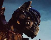
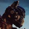
Something very different for me, it is a replica from a PC Game called Metal Gear Solid 4, I am not a gamer in anyway so i don't really know much about it. The guy I built it for has a second battle damaged version to do, there are over 600 individual parts that make up the model and the level of thought and precision with the parts is amazing. Certainly one of the best thought out models i have ever seen, all the joints are articulated and can be positioned in many different ways. It is all snap fit as well with colour coded plastic parts, the difficult bit for me was the painting and the masking, the whole model took 3 weeks to complete. Thanks for looking. Danny
-
1/350 TOS Enterprise WIP.
danimalmagic replied to danimalmagic's topic in Work In Progress - SF & RealSpace
After masking all the windows it was just the painting and decalling left to do, the masking was well worth the time and proved much more effective than using a liquid mask. Thanks for looking. DannyNext up was the decals, you have to be pretty careful with the Polar Lights decals as they are very thick and prone to silvering even with a few coats of Future applied first. Even then you still need plenty of Microset to get them right, the weathering decals even more so. The weathering decals for the dish come in large triangular segments and are very easy to damage so lots of soapy water and more microset. To aid driving the air bubbles out i had to employ a small paint roller, the underside of the suacer is the worse part. Lastly the shuttle. This just left the final assembly. A short Video, lights and motors. https://1drv.ms/v/s!Aqom4v1uZi83g358_08NuAHMOu2_ Motors before machining the clearances. https://1drv.ms/v/s!Aqom4v1uZi83hACdkKJWciWIcA4D Regards -
1/350 TOS Enterprise WIP.
danimalmagic replied to danimalmagic's topic in Work In Progress - SF & RealSpace
Flat out this week to try and get here finished, paint on today, just decalling which is a mission on its own then final assembly. Thanks for looking. Danny -
1/350 TOS Enterprise WIP.
danimalmagic replied to danimalmagic's topic in Work In Progress - SF & RealSpace
Hi all, I started the week with making up the lighting for the fuselage and fitting ready to glue the halves together, once complete the necessary lighting test. With that done the halves could be glued together, once done it was left for 24hrs and I then filled the join seam, this took a few goes to get it right. The same thing was done to the nacelles, the seams here took a little more effort. In between coats of filler and rubbing down I moved on to making the corrections to the Bussard spinner motors. One of the disappointing things about these are the noise they make. The motor vibration resonates right through the plastic and the into the Bussard as a whole and this amplifies it even more as follows. Ahh it is at this point I realise you can not link quick time video (MOV) via Photobucket. Basically the motor has a small deduction gearbox on the end and it makes a lot of noise which kind off detracts from the finished model. I started off by machining the spinners, these wobble on all axis, I have machined so at least the back of them runs true and it will also give us some clearance as they rub, should stop the squeaking. Next up were the motors, I was going to open the hole out and then fit the motors using silicon mastic hoping this would create a little dampening of the vibration. While discussing that with the customer he mentioned a video he had seen and the use of Velcro. Using Velcro really is a good idea and should hold the motor firmly on centre and hopefully reduce the vibration. Next I machined the larger clearance hole for the motors. Motor fitted and is a nice snug fit, I thought I would need to mechanically fix it in some way but it is fine as it is. I then took a small amount of material off the outer diameter to give us some more clearance and hopefully reduce vibration a bit more. The coloured reflectors for the Bussards were shortened before fitting, this should ensure the spinner does not rub on them, cut at 45 degree so they sit as far down as possible on the LED. Mounting plate sprayed silver to aid lighting. I have also opened up the hole in the lamp holder just to make sure there is no rubbing here either. Finally as the spinner passes through the PCB I have carefully opened out he hole to make sure there is clearance. In between all this I have sprayed of the sub parts ready for fitting, some still require further masking and additional paint. Light test of fuselage and shuttle bay. Lastly for the week was masking all the windows, I had hoped to get it all done but yesterday but it is quite a lengthy job so I will continue today. The last time I did this I used a liquid mask and it worked well but took forever to remove the liquid mask after as it get drawn into the recesses of the window. This time I am using masking tape, time consuming but it should be a better result in the end. Next phase is to get the masking done so i can spray and start adding the decals, not sure if it will be done this week but we will see. Thanks for looking. Danny -
1/350 TOS Enterprise WIP.
danimalmagic replied to danimalmagic's topic in Work In Progress - SF & RealSpace
Hi all, another busy week with the bulk of the niggly jobs done, I started off with getting the dish glued together and this was left firmly clamped for 24 hours. While that was curing I moved on to foiling and lighting the neck. Next up was masking the hanger bay ready for painting, quite a lengthy job on its own. Hanger bay has an initial coat of black for light seepage and the then was coated with white to give a level base and then the topcoats are applied. Decals on. With that done I could assemble ready for lighting. Lighting in place are and the shuttle bay is ready, this needs to be as neat as possible as fitting the bay is beyond tight. This is the initial fit of the shuttle bay and as you can see the two halves are nowhere near close to fitting. The only way to fit the bay is to remove material from the inside so a bit of careful work with the Dremmel was required along with a fair few test fits. I had glued in the windows prior to this operation. Next the area was hand sanded and the area light sealed with black and silver making sure to mask the windows. The two halves now close up nicely with no stress on the shuttle bay lighting. Next I removed the seam from the two halves of the dish, I used a liquid filler here, it took a couple of applications and a bit of sanding but removing the join is a must. The black line is a mixture of the glue and black paint residue after sanding, there is no seam left. Dish lighting check. Next the nacelles were assembled and again the seam is filled with liquid filler, the seams are not too bad here so preparing for paint should be quite straight forward. The next job was foiling the lower fuselage and adding the lights, again all hard soldered with each LED strip being fixed to a piece of rubber to make sure it is electrically insulated to Aluminium foil. The last thing to do for the week was the base for the shuttle deck, this is actually a transparent part but needs to be masked so that the coloured areas can be illuminated from behind. That is pretty well all the hard stuff done now so the plan for this week is to get all the main sub-assemblies glued together and get them painted. I also want to do the machining to the nacelle Bussards to reduce the noise form the motors, I will come to that in more detail next week. Thanks for looking. Danny. -
Hi all a bit of a change for me, i did build one of these a few years ago, I will be lighting it using the Polar Lights lighting kit. When i did the first one I never did an in depth WIP so for those who like a little Sci-Fi here we go. Man Cave date 29082016, 4 week mission to boldly go where many other modellers have gone before. A bit of school bus nostalgia from back in the day. https://www.youtube.com/watch?v=FCARADb9asE I started with the dish halves, any parts that are going to be lighted need to be light sealed from the inside. No difficulties here just a base coat of matt black. Once dried I have applied a second coat of Tamiya Aluminium this further aids light sealing and also helps increase reflectivity inside the model. The same has been done for all lighted parts. To further amplify the lighting effect inside I now apply some aluminium foil to any of the large areas within the dish, the polished finish will massively increase the lighting effect. You do not need to cover every square inch with foil as we have the silver base coat for any awkward areas. With that done I marked the position of the parts that make up the various windows. Then removed the foil from those areas so that the part can be securely fixed in place. Window parts all fixed in place, the top half of the saucer is not an issue as all the parts are fitted externally and can be done at the end. Next step is the fitting of the Polar Lights Lighting Kit, there are many good points with this kit and it is well thought out but you cannot trust the LED strip connectors to stay in place, I found this out the hard way on the 1st one I built. Basically I had to split the saucer and hard solder the connections, I am not even taking the risk this time so every connection will be properly soldered. As i am not lighting the nacelles this gives us some spare LED strip, I have used 3 more on the centre of the lower dish, these will direct more light up and under the bridge to increase the illumination effect. Anywhere that the LED strip will come into contact with the foil has to be insulated, I have simply glued in some rubber pads and fixed the LED to them. The next thing to do is paint the impulse engine LED red and then create a shield to stop the red light bleeding into the rest of the dish. Quick test. A test of the completed dish lighting. The last thing to do before sealing up the dish is to further light seal the impulse engine cover, I have filled any voids and painted black and silver again. The gap at the front will be sealed when the top of the dish is sitting on it. The bridge was also painted, the bridge it small to say the least but from past experience you can get a good effect once completed, windows left cleat at this point. Next I have added various colours to the underside of the bridge controls the idea being that apply small pin picks etc to the top surface that will allow light to penetrate through making the panels illuminated with various buttons etc. All areas I do not want light coming through are painted black. Next the decals are applied to the clear parts to represent the various screens, these need further painting as I only want light coming though the screen area. Bridge fitted in position, very difficult to get good images but it looks far better by eye. The plan for next week will be to aluminium foil the lower hull and neck and get the lighting fitted I will also close up the saucer section and fill the seam in preparation to painting. I am sure there will be plenty of other things to do but I will cover that next week. Thanks for looking. Danny
- 9 replies
-
- 11
-
-
1/25 A.I.T.M Rubber Duck Mack Truck Complete.
danimalmagic replied to danimalmagic's topic in Ready For Inspection - Vehicles
Thanks Vince, I am not sure if the customer is into Smokey, an interesting Idea though. Thanks for looking. Danny -
1/25 A.I.T.M Rubber Duck Mack Truck Complete.
danimalmagic replied to danimalmagic's topic in Ready For Inspection - Vehicles
Hi Wayne, have a read through the wip, you will find it east enough, all decals supplied with the kit. Thanks for looking. Danny -
1/25 A.I.T.M Rubber Duck Mack Truck Complete.
danimalmagic replied to danimalmagic's topic in Ready For Inspection - Vehicles
Cheers buddy, I am not the most knowledgeable when it comes to trucks so I got some guidance from Dave at MITB, would have really struggled otherwise. Know I have got the hang of the specifics it would be a lot easier if i ever have to another. Thanks for looking. Danny -
A.I.T.M, Rubber Duck Mack Truck WIP.
danimalmagic replied to danimalmagic's topic in Work In Progress - Vehicles
Complete project on ready for inspection. Danny -
1/25 A.I.T.M Rubber Duck Mack Truck Complete.
danimalmagic replied to danimalmagic's topic in Ready For Inspection - Vehicles
This is mot the plastic kit it is the A.I.T.M resin kit, the WIP is on work on progress. Thanks for looking. Danny -
1/25 A.I.T.M Rubber Duck Mack Truck Complete.
danimalmagic replied to danimalmagic's topic in Ready For Inspection - Vehicles
Thanks guys, a challenging but enjoyable project. Thanks for looking. Danny -
Well that is another cool little project completed, hope you all enjoy, as usual a few pictures. Add some music for a little nostalgia. https://www.youtube.com/watch?v=Sd5ZLJWQmss Thanks for looking. Danny Add some music for a little nostalgia. https://www.youtube.com/watch?v=Sd5ZLJWQmss
-
A.I.T.M, Rubber Duck Mack Truck WIP.
danimalmagic replied to danimalmagic's topic in Work In Progress - Vehicles
Thanks guys, should be done tomorrow. Danny -
A.I.T.M, Rubber Duck Mack Truck WIP.
danimalmagic replied to danimalmagic's topic in Work In Progress - Vehicles
Hi all, it’s been another very busy week but I am nearly there, I should have the model completed tomorrow/Tuesday. Ok, I will begin with a correction to the orientation of the air cylinders and battery boxes, I had somehow managed to fit upside down. The good thing about pinning parts in place is it makes it nice and easy to correct errors like this, better now. Next the sleeper cab, as it is very difficult to accurately replicate the interior and the fact is that most of it you will not be able to see so I have made and fitted a curtain, you can see a curtain clear enough in the film so this is a sensible fix. Next I needed to work out and drill all the mounting points for the two off set horns and the wing mirrors, I have some really good images so they should be pretty spot on. The 5 orange lights are just temporarily fixed in place with blue tack so I could get the positioning right. The hand rails were next and these are just made from two paper clips. Lastly for the sleeper cab are the 3 spotlights, I have looked online and some of them are round and some are rectangular so I made best use of what I had to hand. The backs of these will be painted silver then over coated with black so they will look quite reflective. The last detail for the sleeper cab are the reflective orange discs, there are four each side, I have used some clear orange sheet and sprayed silver on the back. If I just put them on without the silver then the black background of the paint would make them really dark. They actually have a nice reflective quality to them so they will look hopefully quite realistic. The next step was to position the front bars and then pin then in position for later fitting. Transmission shaft painted and fitted. The next thing to sort out is the exhaust stack, this is a real prominent feature and there is no way I can achieve the level of finish required with the resin part so more drastic action required, note height above cab. I decided the best bet was to machine a new one so I started with a suitable stainless steel bolt I have machined so that the mounting braces are raised bands on the surface. The next step was to fit some aluminium tube and polish, I had some old Albion Alloy tube which was perfect for the job. ( good old autosol) Lastly was the bend at the base of the stack, bending thin wall small diameter pipe without flattening it is tricky so I machined another stainless steel bolt and bent to suit. Completed stack ready for fitting, the bend will be cut to length once the stack is in place and the pipe at the top shortened as required, the resin part is way to short. Next are the cab access steps, these would be pretty tough to get aligned perfectly with super glue in one go and would not be very strong so I have pinned these as well. Mounted, I have applied a dark wash too. Next was the fifth wheel, I have changed a few of these in real life and they are always covered in a layer of dark grease which hides some of the nastiest splinters you will ever see, I only got bitten the once. Fifth wheel is screwed in so it can be moved to the rear but from my point of view it will stay over the rear axles. Next was the cab interior, I had some good images so I have just replicated best as possible, it looks a bit better by eye. For an extra bit of detail I have made up a CB. Air filter masked and painted with Alclad Aluminium. The mounting of the wind breaker was next, it should have support brackets behind it as below, one each side as far as I can tell. I have replicated best as with stock styrene channel. The cab window glass proved to be quite tricky, the side windows were easy enough but I have to heat and bend the ends of the main window to match the bend of the cab. The styrene sheet supplied was a little to thin so I have used a slightly thicker piece, to maintain the curve the interior was packed with foam until the UPVA glue went off. Next bit of detail are the orange lights on the cab top, these again are Alclad Aluminium with Tamiya Clear orange for the light. That is basically it for this week, I have started adding the decals and the final assembly should be done by Tuesday, I still have a few more bits of detail to add yet but they can only be done when everything is in place. It will then be at that point I will start making it all look a bit more dusty. That’s it for now. Thanks for looking. Danny